In order to ensure the supply of voltage from the distribution device to the end consumer, power lines are used. They can be overhead or cable and have a considerable length.
Like all conductors, they have a resistance that depends on the length and the longer they are, the greater the voltage loss.
And the longer the line, the greater the voltage loss will be. Those. The voltage at the input and at the end of the line will be different.
In order for the equipment to operate without failures, these losses are normalized. Their total value should not exceed 9%.
The maximum voltage drop at the input is five percent, and to the most remote consumer no more than four percent. In a three-phase network with a three or four wire network, this figure should not exceed 10%.
Voltage drop on the wire
The article will be specific, with theoretical calculations and formulas. For those who are not interested in what comes from and why, I advise you to go straight to Table 2 - Selecting the wire cross-section depending on the current and voltage drop.
And also - calculation of voltage losses on a long powerful three-phase cable line. An example of calculating a real line.
So, if we take the power constant, then as the voltage decreases, the current should increase, according to the formula:
P = I U. (1)
In this case, the voltage drop on the wire (losses in the wires) due to resistance is calculated based on Ohm’s law:
U = R I. (2)
From these two formulas it is clear that as the supply voltage decreases, the losses on the wire increase. Therefore, the lower the supply voltage, the larger the cross-section of the wire must be used to transmit the same power.
For direct current, where low voltage is used, you have to carefully approach the issue of cross-section and length, since these two parameters determine how many volts will be wasted.
How to use an online calculator?
In the finished table you need to enter data according to the selected cable material, system load power, network voltage, cable temperature and method of laying it. Then click the “calculate” button and get the finished result. This calculation of voltage losses in a line can be safely used in work, if you do not take into account the resistance of the cable line under certain conditions:
- When specifying the power factor, cosine phi is equal to one.
- DC network lines.
- AC network with a frequency of 50 Hz made of conductors with cross-sections up to 25.0-95.0.
The results obtained must be used according to each individual case, taking into account all the errors of cable and wire products.
Be sure to fill in all values!
DC resistance of copper wire
The wire resistance depends on the resistivity ρ, which is measured in Ohm mm²/m. The resistivity value determines the resistance of a piece of wire 1 m long and 1 mm² cross-section.
The resistance of the same piece of copper wire 1 m long is calculated by the formula:
R = (ρ l) / S, where (3)
R – wire resistance, Ohm,
ρ – wire resistivity, Ohm mm²/m,
l – wire length, m,
S – cross-sectional area, mm² .
The resistance of the copper wire is 0.0175 Ohm mm²/m; we will use this value in further calculations.
It is not a fact that copper cable manufacturers use pure copper “0.0175 standard”, so in practice the cross-section is always taken with a margin, and against wire overload they use protective circuit breakers, also with a margin.
From formula (3) it follows that for a piece of copper wire with a cross-section of 1 mm² and a length of 1 m, the resistance will be 0.0175 Ohm. For a length of 1 km – 17.5 Ohms. But this is only a theory, in practice everything is worse.
Below I will give a plate calculated using formula (3), which shows the resistance of a copper wire for different cross-sectional areas.
Table 0. Resistance of copper wire depending on cross-sectional area
| S, mm² | 0,5 | 0,75 | 1 | 1,5 | 2,5 | 4 | 6 | 10 |
| R for 1m | 0,035 | 0,023333 | 0,0175 | 0,011667 | 0,007 | 0,004375 | 0,002917 | 0,00175 |
| R for 100m | 3,5 | 2,333333 | 1,75 | 1,166667 | 0,7 | 0,4375 | 0,291667 | 0,175 |
Symptoms of low voltage in a consumer
If these indicators are not met, end users will not be able to provide the nominal parameters. When the voltage decreases, the following symptoms occur:
- Lighting devices that use incandescent lamps begin to work (glow) at half incandescence;
- When the electric motors are turned on, the starting force on the shaft decreases. As a result, the motor does not rotate, and as a result, the windings overheat and fail;
- Some electrical appliances do not turn on. There is not enough voltage, and other devices may fail after switching on;
- Installations that are sensitive to input voltage are unstable, and light sources that do not have an incandescent filament may also not turn on.
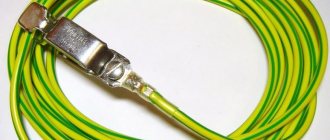
Electricity is transmitted via overhead or cable networks. Overhead ones are made of aluminum, while cable ones can be aluminum or copper.
In addition to active resistance, cables contain capacitive reactance. Therefore, the power loss depends on the cable length.
Calculation of voltage drop on a wire for direct current
Now, using formula (2), we calculate the voltage drop on the wire:
U = ((ρ l) / S) I, (4)
That is, this is the voltage that will drop on a wire of a given cross-section and length at a certain current.
These are the tabular data for a length of 1 m and a current of 1A:
Table 1. Voltage drop on a 1 m copper wire of different cross-sections and a current of 1A:
| S, mm² | 0,5 | 0,75 | 1 | 1,5 | 2,5 | 4 | 6 | 8 | 10 |
| U, B | 0,0350 | 0,0233 | 0,0175 | 0,0117 | 0,0070 | 0,0044 | 0,0029 | 0,0022 | 0,0018 |
This table is not very informative; it is more convenient to know the voltage drop for different currents and cross sections. Let me remind you that calculations for choosing the wire cross-section for direct current are carried out according to formula (4).
Table 2. Voltage drop for different wire cross-sections (top row) and current (left column). Length = 1 meter
| S,mm² I,A | 1 | 1,5 | 2,5 | 4 | 6 | 10 | 16 | 25 |
| 1 | 0,0175 | 0,0117 | 0,0070 | 0,0044 | 0,0029 | 0,0018 | 0,0011 | 0,0007 |
| 2 | 0,0350 | 0,0233 | 0,0140 | 0,0088 | 0,0058 | 0,0035 | 0,0022 | 0,0014 |
| 3 | 0,0525 | 0,0350 | 0,0210 | 0,0131 | 0,0088 | 0,0053 | 0,0033 | 0,0021 |
| 4 | 0,0700 | 0,0467 | 0,0280 | 0,0175 | 0,0117 | 0,0070 | 0,0044 | 0,0028 |
| 5 | 0,0875 | 0,0583 | 0,0350 | 0,0219 | 0,0146 | 0,0088 | 0,0055 | 0,0035 |
| 6 | 0,1050 | 0,0700 | 0,0420 | 0,0263 | 0,0175 | 0,0105 | 0,0066 | 0,0042 |
| 7 | 0,1225 | 0,0817 | 0,0490 | 0,0306 | 0,0204 | 0,0123 | 0,0077 | 0,0049 |
| 8 | 0,1400 | 0,0933 | 0,0560 | 0,0350 | 0,0233 | 0,0140 | 0,0088 | 0,0056 |
| 9 | 0,1575 | 0,1050 | 0,0630 | 0,0394 | 0,0263 | 0,0158 | 0,0098 | 0,0063 |
| 10 | 0,1750 | 0,1167 | 0,0700 | 0,0438 | 0,0292 | 0,0175 | 0,0109 | 0,0070 |
| 15 | 0,2625 | 0,1750 | 0,1050 | 0,0656 | 0,0438 | 0,0263 | 0,0164 | 0,0105 |
| 20 | 0,3500 | 0,2333 | 0,1400 | 0,0875 | 0,0583 | 0,0350 | 0,0219 | 0,0140 |
| 25 | 0,4375 | 0,2917 | 0,1750 | 0,1094 | 0,0729 | 0,0438 | 0,0273 | 0,0175 |
| 30 | 0,5250 | 0,3500 | 0,2100 | 0,1313 | 0,0875 | 0,0525 | 0,0328 | 0,0210 |
| 35 | 0,6125 | 0,4083 | 0,2450 | 0,1531 | 0,1021 | 0,0613 | 0,0383 | 0,0245 |
| 50 | 0,8750 | 0,5833 | 0,3500 | 0,2188 | 0,1458 | 0,0875 | 0,0547 | 0,0350 |
| 100 | 1,7500 | 1,1667 | 0,7000 | 0,4375 | 0,2917 | 0,1750 | 0,1094 | 0,0700 |
What explanations can be made for this table?
1. in red those cases when the wire will overheat, that is, the current will be higher than the maximum permissible for a given cross-section. I used the table given on SamElektrika: Selecting the cross-sectional area of the wire.
2. Blue color - when the use of too thick wire is economically and technically impractical and expensive. The threshold was taken to be a drop of less than 1 V over a length of 100 m.
Reduce losses
It is quite obvious that losses depend on the length of the conductor in the line. The higher this parameter is, the more the voltage drops. Several methods can be used to reduce losses:
- Increase the conductor cross-section to evenly distribute the load on the line.
- Reduce the cable length, which is not always possible.
- Reduce the power of current transmitted through a long wire.
The latter method works great in power networks that have several backup lines. It should also be remembered that the voltage may drop as the temperature of the cable increases. If additional thermal insulation measures are used during cable installation, losses can be reduced.
In the energy industry, calculating the voltage drop on the main line is one of the most important tasks. If all calculations were carried out correctly, then the consumer will not have problems with the operation of electrical equipment.
How to use the section selection table?
Table 2 is very easy to use. For example, you need to power a certain device with a current of 10A and a constant voltage of 12V. The line length is 5 m. At the output of the power supply we can set the voltage to 12.5 V, therefore, the maximum drop is 0.5 V.
Available - wire with a cross-section of 1.5 square. What do we see from the table? At 5 meters with a current of 10 A we will lose 0.1167 V x 5m = 0.58 V. It seems to be suitable, considering that most consumers tolerate a deviation of +-10%.
But. After all, we actually have two wires, plus and minus, these two wires form a cable on which the load supply voltage drops. And since the total length is 10 meters, the drop will actually be 0.58 + 0.58 = 1.16 V.
In other words, in this situation, the output of the power supply unit is 12.5 Volts, and the input of the device is 11.34. This example is relevant for powering an LED strip.
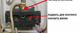
And this is without taking into account the contact resistance of the contacts and the imperfection of the wire (“sample” of copper is not the same, impurities, etc.)
Therefore, such a piece of cable most likely will not work; you need a wire with a cross-section of 2.5 square. It will give a drop of 0.7V on a 10m line, which is acceptable.
What if there is no other wire? There are two ways to reduce voltage loss in wires.
1. The 12.5 V power supply should be placed as close to the load as possible. If we take the example above, 5 meters will suit us. This is what they always do to save on wires.
2. Increase the output voltage of the power supply. The risk is that as the load current decreases, the voltage across the load may rise to unacceptable limits.
For example, in the private sector, 250-260 Volts are installed at the output of the transformer (substation); in houses near the substation, the light bulbs burn like candles. I mean, not for long. And residents on the outskirts of the area complain that the voltage is unstable and drops to 150-160 Volts. Loss of 100 Volts! Multiplied by the current, you can calculate the power that heats the street, and who pays for it? We, the “losses” column on the receipt.
Checking the cable for voltage loss
Everyone knows that the flow of electric current through a wire or cable with a certain resistance is always associated with a loss of voltage in this conductor.
According to the rules of the River Register, the total loss of electrical voltage in the main distribution board to all consumers should not exceed the following values:
- for lighting and signaling at a voltage of more than 50 volts - 5%;
- for lighting and signaling at a voltage of 50 volts - 10%;
- for power consumption, heating and heating systems, regardless of electrical voltage – 7%;
- for power consumption with short-term and intermittent operating modes, regardless of electrical voltage – 10%;
- when starting engines – 25%;
- when powering a radio switchboard or other radio equipment or when charging batteries – 5%;
- when supplying electricity to generators and distribution boards - 1%.
You might be interested in this. Features of SHDUP U4
Based on this, various types of cables capable of supporting such voltage loss are selected.
Example of a calculator for automating calculations
Conclusion on choosing the wire cross-section for constant voltage:
The shorter and thicker the wire through which direct current flows, the lower the voltage drop across it, the better . That is, the voltage loss in the wires is minimal.
If you look at Table 2, you need to select the values from the top-right, without going into the “blue” zone.
For alternating current the situation is the same, but the issue is not so acute - there power is transferred by increasing the voltage and decreasing the current. See formula (1).
In conclusion, here is a table in which the DC voltage drop is set to a limit of 2%, and the supply voltage is 12 V. The required parameter is the maximum wire length.
Attention! This refers to a two-wire line, for example a cable containing 2 wires. That is, the case when, through a cable 1 m long, the current makes a path of 2 m, back and forth. I brought this option because... it is most often encountered in practice. For one wire, to find out the voltage drop across it, you need to multiply the number inside the table by 2. Thanks to attentive readers!
Table 3. Maximum wire length for 2% DC voltage drop.
| S,mm² I,A | 1 | 1,5 | 2,5 | 4 | 6 | 10 | 16 | 25 | 35 | 50 | 75 | 100 |
| 1 | 7 | 10,91 | 17,65 | 28,57 | 42,86 | 70,6 | 109,1 | 176,5 | 244,9 | – | – | – |
| 2 | 3,53 | 5,45 | 8,82 | 14,29 | 21,4 | 35,3 | 54,5 | 88,2 | 122,4 | 171,4 | – | – |
| 4 | 1,76 | 2,73 | 4,41 | 7,14 | 10,7 | 17,6 | 27,3 | 44,1 | 61,2 | 85,7 | 130,4 | – |
| 6 | 1,18 | 1,82 | 2,94 | 4,76 | 7,1 | 11,7 | 18,2 | 29,4 | 40,8 | 57,1 | 87 | 117,6 |
| 8 | 0,88 | 1,36 | 2,2 | 3,57 | 5,4 | 8,8 | 13,6 | 22 | 30,6 | 42,9 | 65,25 | 88,2 |
| 10 | 0,71 | 1 | 1,76 | 2,86 | 4,3 | 7,1 | 10,9 | 17,7 | 24,5 | 34,3 | 52,2 | 70,6 |
| 15 | – | 0,73 | 1,18 | 1,9 | 2,9 | 4,7 | 7,3 | 11,8 | 16,3 | 22,9 | 34,8 | 47,1 |
| 20 | – | – | 0,88 | 1,43 | 2,1 | 3,5 | 5,5 | 8,8 | 12,2 | 17,1 | 26,1 | 35,3 |
| 25 | – | – | – | 1,14 | 1,7 | 2,8 | 4,4 | 7,1 | 9,8 | 13,7 | 20,9 | 28,2 |
| 30 | – | – | – | – | 1,4 | 2,4 | 3,6 | 5,9 | 8,2 | 11,4 | 17,4 | 23,5 |
| 40 | – | – | – | – | – | 1,8 | 2,7 | 4,4 | 6,1 | 8,5 | 13 | 17,6 |
| 50 | – | – | – | – | – | – | 2,2 | 3,5 | 4,9 | 6,9 | 10,4 | 14,1 |
| 100 | – | – | – | – | – | – | – | 1,7 | 2,4 | 3,4 | 5,2 | 7,1 |
| 150 | – | – | – | – | – | – | – | – | – | 2,3 | 3,5 | 4,7 |
| 200 | – | – | – | – | – | – | – | – | – | – | 2,6 | 3,5 |
According to this table, our one and a half rack can only be 1 meter long. It will drop 2%, or 0.24V. We check using formula (4) - everything agrees.
If the voltage is higher (for example, 24 V DC), then the length can be correspondingly longer (2 times).
All of the above applies not only to constant voltage, but also to low voltage in general. And when choosing a cross-sectional area in such cases, one should be guided not only by the heating of the wire, but also by the voltage drop across it. For example, when powering halogen lamps through a step-down transformer.
Please comment on the article, how does theory coincide with practice?
Opportunities for reducing losses
The main way to reduce losses in a cable is to increase its cross-sectional area. In addition, you can reduce the length of the conductor and reduce the load. However, the last two methods cannot always be used due to technical reasons. Therefore, in many cases, the only option is to reduce the cable resistance by increasing the cross-section.
A significant disadvantage of a large cross-section is considered to be a noticeable increase in material costs. The difference becomes noticeable when cable systems stretch over long distances. Therefore, at the design stage, you must immediately select a cable with the required cross-section, for which you will need to calculate the power loss using a calculator. This program is of great importance when drawing up projects for electrical installation work, since manual calculations take a lot of time, and in the online calculator mode the calculation takes literally a few seconds.
Online calculator for calculating voltage losses in a cable
Long cable lines are characterized by significant resistance, which makes adjustments to the operation of the network. Depending on the brand of cable and other parameters, the resistance value will also differ. And the amount of voltage on the cable line is directly proportional to this resistance.
Using an online calculator, calculating voltage losses in a cable comes down to the following steps:
- Indicate the cable length in meters and the material of the current-carrying conductors in the appropriate boxes;
- Conductor cross-section in mm²;
- The amount of electricity consumed in amperes or watts (place the indicator next to the power or current, depending on what parameter you know and what value you will indicate);
- Enter the voltage value in the network;
- Enter the power factor cosφ;
- Specify the cable temperature;
After you have entered the above data into the fields of the calculator, click the “calculate” button and in the corresponding columns you will receive the calculation result - the amount of voltage loss in the cable ΔU in%, the resistance of the wire itself Rpr in Ohm, the reactive power Qpr in VAR and the voltage at the load Un.
To calculate these values, the entire system, including cable and load, is replaced with an equivalent one, which can be represented as follows:
Line equivalent circuit with load
As you can see in the figure, depending on the type of power supply to the load (single-phase or three-phase), the resistance of the cable line will have a series or parallel connection with respect to the load. Calculation in the calculator is carried out using the following formulas:
Where,
- ΔU – voltage loss;
- UЛ – linear voltage;
- UФ – phase voltage;
- I – current flowing in the line;
- ZK – cable line impedance;
- RK – active resistance of the cable line;
- XK – cable line reactance.
Of these, UЛ, UФ, I, are specified at the data entry stage. To determine the total resistance ZK, the arithmetic addition of its active RK and reactive XK components is performed. Active and reactive resistance is determined by the formulas:
- RК = (ρ * l) / S
- RК – active resistance of the cable line, where
- ρ is the resistivity for the corresponding metal (copper or aluminum), but the value of the resistivity of the material is not constant and can vary depending on the temperature, which is why, to bring it to real conditions, recalculation is performed in relation to temperature:
- ρt = ρ20 *
- Here:
- a is the coefficient of temperature change in the resistivity of the material.
- ρ20 – specific resistance of the material at a temperature of +20ºС.
- t is the actual temperature of the conductor at a given time.
- l – cable line length (if the load is single-phase and the cable has two cores, then both of them are connected in series and the length must be multiplied by 2)
- S – cross-sectional area of the conductor.
- Knowing the active resistance, you can calculate the reactive XK, through the power factor using the following formula:
- Reactive power is determined by the following formula: Q = S*sin φ, where
- Where S is the apparent power, which can be defined as the product of the current in the circuit and the input voltage of the source or as the ratio of active power to power factor.
- To calculate the voltage per load, the following calculations are made: UH = U - ΔU, where
- Where UН is the voltage applied to the load;
- U – voltage at the input to the cable line
- ΔU – voltage drop in the cable line.
Voltage drop calculations
DC / single phase calculation
The voltage drop V in volts (V) is equal to the wire current I in amps (A) times 2 times one way wire length L in feet (ft) times the wire resistance per 1000 feet R in ohms (Ω/kft) divided by 1000:
Vdrop (V) = Iwire (A) × Rwire(Ω)
= Iwire (A) × (2 × L(ft) × Rwire(Ω/kft) / 1000(ft/kft))
The voltage drop V in volts (V) is equal to the wire current I in amps (A) times 2 times one way wire length L in meters (m) times the wire resistance per 1000 meters R in ohms (Ω/km) divided by 1000:
Vdrop (V) = Iwire (A) × Rwire(Ω)
= Iwire (A) × (2 × L(m) × Rwire (Ω/km) / 1000(m/km))
3 phase calculation
The line to line voltage drop V in volts (V) is equal to square root of 3 times the wire current I in amps (A) times one way wire length L in feet (ft) times the wire resistance per 1000 feet R in ohms (Ω/kft) divided by 1000:
Vdrop (V) = √3 × Iwire (A) × Rwire (Ω)
= 1.732 × Iwire (A) × (L(ft) × Rwire (Ω/kft) / 1000(ft/kft))
The line to line voltage drop V in volts (V) is equal to square root of 3 times the wire current I in amps (A) times one way wire length L in meters (m) times the wire resistance per 1000 meters R in ohms (Ω/km) divided by 1000:
Vdrop (V) = √3 × Iwire (A) × Rwire (Ω)
= 1.732 × Iwire (A) × (L(m) × Rwire (Ω/km) / 1000(m/km))
Wire diameter calculations
The n gauge wire diameter dn in inches (in) is equal to 0.005in times 92 raised to the power of 36 minus gauge number n, divided by 39:
dn (in) = 0.005 in × 92(36-n)/39
The n gauge wire diameter dn in millimeters (mm) is equal to 0.127mm times 92 raised to the power of 36 minus gauge number n, divided by 39:
dn (mm) = 0.127 mm × 92(36-n)/39
Wire cross sectional area calculations
The n gauge wire's cross sercional area An in kilo-circular mils (kcmil) is equal to 1000 times the square wire diameter d in inches (in):
An (kcmil) = 1000×dn2 = 0.025 in2 × 92(36-n)/19.5
The n gauge wire's cross sercional area An in square (in2) is equal to pi divided by 4 times the square wire diameter d in inches (in):
An (in2) = (π/4)×dn2 = 0.000019635 in2 × 92(36-n)/19.5
The n gauge wire's cross sercional area An in square millimeters (mm2) is equal to pi divided by 4 times the square wire diameter d in millimeters (mm):
An (mm2) = (π/4)×dn2 = 0.012668 mm2 × 92(36-n)/19.5