In order to reduce the cost of high-voltage devices in various industries, manufacturers are replacing special high-voltage switches with short circuiters and separators.
Such a system can be found at some substations with a power of 40 kV and more, but generally, this approach is no longer considered relevant.
Since this scheme is still used in the CIS countries, within the framework of this publication we will talk about it and its components: separators separately.
Short circuit and separator device
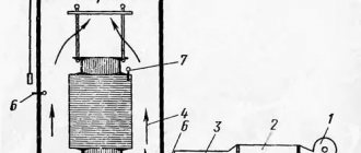
Let's briefly talk about the design of the electromechanical devices shown above, this will be useful in explaining their operating principle. Let's start with the separator; its simplified drawing is presented below (Fig. 3 1).
Figure 3. 1) separator design; 2)short circuit design
Designations (part 1 separator design):
- A1 – insulating posts.
- B1 – rotating rods with knives installed in contacts.
- C1 is a spring mechanism that drives the rotary rods.
- D1 – platform.
- E1 – a cabinet with an electromagnetic “trigger” mechanism that releases a spring drive that separates the contact parts.
Both the devices themselves and the mechanics of their operation are not complicated. We have already mentioned that the separator is used when the voltage is removed from the network, that is, when the switches on the supply line are turned on. Consequently, there is no need to install special vacuum arcing contact chambers on the disconnectors.
Now let's look at the main design elements of the short circuit (Fig. 3 2):
- A2 – main (support) insulator rod.
- B2 – fixed rod with contact knives.
- C2 – spring drive.
- D2 – platform on which the short circuit is installed.
- E2 – cabinet for electromagnetic drive and current transformer.
- F2 is a movable grounded rod that closes the poles of the short circuit.
Structurally, the KZ-35 short circuiter, as well as other models that create an artificial interphase short circuit, have several differences from the device shown in the figure. Since a linear short circuit is simulated, the movable one is not connected to the ground, it is connected to another phase. Accordingly, the structure is equipped with another insulator-rack.
GENERAL INFORMATION
Currently, standard circuits of high-voltage substations without switches on the supply line have been developed. This makes it possible to reduce the cost and simplify the equipment while maintaining high reliability. Short circuiters and separators are used to replace circuit breakers on the high voltage side.
A short circuiter is a high-speed contact device that, based on a relay protection signal, creates an artificial short circuit in the network.
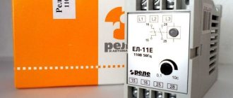
Outdoor short circuiters with a ShPK drive (short circuit drive in the cabinet) and a TShL 0.5 current transformer (bus current transformer, with cast insulation, accuracy class 0.5) are designed to create an artificial short circuit (two-phase for KZ-35 or to ground for KZ-110, KZ-220) in case of damage in the transformer. Under the influence of protection, a short circuit causes the switches installed at the supply ends of the lines to turn off.
The short circuiter is controlled by the ShKK drive, and the short circuiter is turned on automatically under the action of a spring mechanism when the drive is triggered by a relay protection signal. If necessary, the short circuiter can also be turned on manually. The short circuiter is switched off only during manual operation.
The separator is a disconnector that quickly turns off a de-energized circuit after a command is given to its drive. If in a conventional disconnector the shutdown speed is very low, then in a separator the shutdown process lasts 0.5-1.0 s. The separator disconnects damaged sections of the electrical circuit after the safety switch is turned off. The switch is triggered by an artificial short circuit created by a short circuit.
The separators are a two-column disconnector with grounding knives (ODZ); one ODZ-1A, ODZ-1B, two ODZ-2 or without them (OD), controlled by the SHPO drive (separator drive in the cabinet). Up to 110 kV inclusive, three poles of the separator are connected into a common three-pole device and controlled by one SHPO drive.
Separators for 220 kV are made in the form of three separate poles, each of which is controlled by an independent drive.
The separator is switched off automatically under the action of wound springs when a blocking relay or a shutdown electromagnet is activated, releasing the free release mechanism of the drive. The separator is switched on manually.
Designs of short circuiters and separators:
In Fig. 4.1.1. a short circuiter for a voltage of 35 kV KZ-35 is shown. Dimensions for a 110 kV short circuit are given in parentheses.
Rice. 4.1.1 Short circuiter KZ-35
A support insulator 2 is installed on the steel box 1. At the top of the support insulator there is a fixed contact 3, which is under high voltage. Movable grounded contact - knife 4 is mounted on shaft 5 of the short-circuit drive. Base 1 is isolated from the ground. Shaft 5 is acted upon by a drive spring, which is wound up in the disconnected state. To turn on, a command is sent to the drive electromagnet, which releases the mechanism latch. Under the action of the spring, the knife moves in a vertical plane and grounds contact 3. The turn-on time of such a short circuit is 0.15-0.25 s.
Rice. 4.1.2. Separator
The design of the OD-220 separator for a voltage of 220 kV is based on a two-column disconnector with blades 1 rotating in a horizontal plane, Fig. 4.1.2 The columns 2 are driven by a spring drive 3 with electromagnetic control. In the on position, the actuator springs are grounded. When a command is given, the spring is released and the contacts move apart in 0.4-0.5 s.
This is interesting: The zero in the electrical wiring is heating up - causes and solutions
KZ-110 - short circuiter
Outdoor short circuiters with a drive and current transformer TSHL-0.5 are designed to create an artificial short circuit (two-phase for KRN-35) in case of damage in the transformer and are used in simplified substations at a voltage of 35-220 kV.
The purpose of short circuiters is to quickly create powerful artificial short circuits on the supply lines in case of internal damage to power transformers, which are then turned off by switches. After removing the voltage from the supply line, the damaged transformer is disconnected by turning off the separator, and the line is put into operation by automatic reclosure. Reliable operation of the installations is ensured by a clear sequence of actions of relay protection devices, automation, switching devices, as well as blocking devices between separators and short-circuiters along control circuits.
Short circuiter KZ-110 (a) and its drive (b) .
1 - shielding ring; 2 - fixed contact; 3 - column; 4 - welded frame; 5 - insulator; 6 - bus connecting the short-circuit knife to the ground; 7 - current transformer; 8 - drive; 9 and 24 - thrust; 10 — insulating insert; 11,13, 17, 23 and 25 - levers; 12 - knife; 14, 19 to 26 - slats; 15 - shaft; 16 — holding post; 18 - latch; 20 - disconnecting electromagnet; 21 - blocking relay; 22 — bushing Source
Advantages and disadvantages
Opened separators and short circuits do not work very well in adverse weather conditions. Because of this, a certain structure with a contact system was created, placed in a chamber with SF6 gas.
A 35 kilowatt installation uses 2 poles. More powerful ones (110 kilowatts or more) use one pole. Typical short circuiters take a very long time to operate and therefore it is more advisable to use a device based on a powder charge. Its explosion sets the knife into motion.
It is important to know that when monitoring the condition of the devices, you first need to check the insulation on all parts. That's all I wanted to tell you about the principle of operation, design and purpose of short circuiters and separators
We hope the information was useful and understandable for you!
That's all I wanted to tell you about the operating principle, design and purpose of short circuiters and separators. We hope the information was useful and understandable for you!
We also recommend reading:
The modern organization of high-voltage power lines does not provide for the use of switches at node points connected to the supply lines. Instead, most substations use short circuiters and separators
This concept made it possible, while maintaining a high level of reliability, to significantly reduce the cost of equipment and, not least important, to simplify it. The structure of these electrical devices and the principle of operation will be described below.
Joint operation of the short-circuiter with the separator
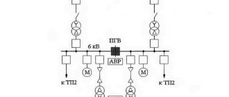
Now let's look at the OD-KZ combination using the example of a substation with two transformer groups powered from one incoming power line.
Example of a substation with OD-KZ
Designations:
- Vk1 – power switch VL (closed).
- Vk2, Vk3 – power protective switches on the low side (closed).
- Vk4 – sector switch (open).
- Kz1, Kz2 – short circuits (open).
- Od1, Od2 – separators (closed).
- Tr1, Tr2 – power transformers 220/10
To get an idea of how this circuit works, consider a situation where one of the transformers fails:
- Let's imagine that the insulation in Tr2 is broken, which leads to the formation of electric discharges that decompose the oil, which is detected by the gas relay and sends a corresponding signal to the control panel of the short circuiter Kz2.
- The signal received by the blocking relay causes it to operate. The mechanism is unlocked and the spring drive pushes the movable rod, as a result, two phases are closed.
- This turns on Vk1, which leads to the disconnection of the supply line and the de-energization of Tp1 and Tp2. A short circuit also causes a corresponding reaction of relay protection Tp2, it turns off Vk3 (the load is removed) and starts Od2. Since the latter has the slowest response speed, it is activated last when the overhead line and load are disconnected.
- After a certain delay, Vk1 reconnects the power line (the automatic restart system is triggered).
- Automatic transfer of reserve includes VK4.
As a result, only Tr1 works at the substation, from which both sections are powered.
Operating principle
A transformer is a device that is an electromagnetic device with 2 (or more) windings. This apparatus is primarily designed to convert alternating current from one voltage to another. Energy transformation occurs due to the magnetic field. Transformer booths are mainly used to conduct electricity over long distances, while at the same time separating and sending it to receivers, rectifiers, and amplifiers of various types of devices. The main component of the above device is a wire with windings. For high-quality operation, short circuiters and separators are installed in transformers, which regulate the serviceability of the device.
Briefly about the short circuiter
A short circuit is a device that creates an unnatural short circuit in electrical lines. Where are such devices used? First of all, the device is installed in transformers. It is used to ensure the disconnection of a faulty transformer after a short circuit has been created during the operation of relay protection of the line it supplies. After this, both the transformer and the line are disconnected from the mains.
How does a short circuit work? The device operates on 2 or 1 pole, depending on the voltage. Installations with 35 kV operate with two poles, and with a voltage of 110 kV or more, one pole is used. You can clearly examine the photo and diagram of the short circuit to understand what it consists of.
Short-circuit circuit diagram KZ-35: (1 – steel box; 2 – support insulator; 3 – fixed contact; 4 – moving grounded knife (contact); 5 – shaft).
The short-circuit gear has a spring that is responsible for turning on the moving knife to a fixed contact, which is currently energized. The relay protection pulses to start the drive, but is manually disabled. To avoid arcing and damage to the device, you need to increase the speed of the knife. In such designs, the short circuiter turns on in 0.15 - 0.5 s.
Briefly about the separator
A separator is a kind of disconnector that quickly turns off the network without current when it is commanded to do so. It can be distinguished from a disconnector due to the spring drive located on the separator. This device is turned on manually. Separators can also have a grounded leg on one side or on both. Let's look at the photo and diagram below to see what the separator consists of:
OD-220 separator diagram: (1 – 2-column disconnector with a knife that rotates; 2 – columns; 3 – spring drive).
Having familiarized ourselves with the diagram, let's see how the separator works. It turns off the circuit (without current) or the magnetizing current, but it is impossible to turn off the short circuit current that appeared during the start of the short circuit. And due to this nuance in the OD and SC circuits there is a blocking that prevents the separator from turning off, provided that current passes through the transformer. Where is this device used? In the transformer booth, to stabilize its operation.
Also, so that the separator does not turn off, a current relay is introduced into the design, which is connected directly to the current transformer located in the short circuit. After disconnecting the line, the relay will close the contact and the capacitor, which will cause it to work. Next, thanks to capacitor 2, a shutdown will occur.
Separator operating method
An electric transformer is an electromagnetic device that has two or more inductively coupled windings. It is used to convert alternating electric current using electromagnetic induction.
The transformation occurs subject to a change in the power of the current itself. Surely, you have seen large transformers located in some areas of the city.
They are used to transmit electricity over vast distances, in addition, they send it to all kinds of receivers and amplifiers of other devices.
As already mentioned, the main component of the separator circuit is a wire with windings. In order for the transformer to work efficiently and properly, a separator-short-circuit circuit is fixed in it.
Security measures.
When installing, testing, switching on, operating and repairing short circuiters, you must be guided by the current “Rules for the safe operation of electrical installations”. Servicing of short circuiters is permitted by persons who have passed the test of knowledge of PTE and PTB and have the appropriate qualification group. It is prohibited to perform operations with short circuits whose insulators are chipped or cracked. When setting up, testing, and checking the operation of the hydraulic buffers of the short-circuit, it is necessary to take precautions to prevent personnel from getting into the areas of movement of levers, rods, and knives. Do not allow foreign objects (keys, bolts, etc.) on the moving parts of the product. Do not allow impacts on the body and flanges of insulators during operation, adjustment, maintenance and repair. During testing, personnel are prohibited from standing on the short circuit
2.2. Designs of short circuiters and disconnectors
In Fig. Figure 2.1 shows a short circuit for a voltage of 35 kV KZ-35. Dimensions for a 110 kV short circuit are given in parentheses. Rice. 2.1 Short circuiter KZ-35 A support insulator 2 is installed on the steel box 1. At the top of the support insulator there is a fixed contact 3, which is under high voltage. Movable grounded contact - knife 4 is mounted on shaft 5 of the short-circuit drive. Base 1 is isolated from the ground. Shaft 5 is acted upon by a drive spring, which is wound up in the disconnected state. To turn on, a command is sent to the drive electromagnet, which releases the mechanism latch. Under the action of the spring, the knife moves in a vertical plane and grounds contact 3. The turn-on time of such a short circuit is 0.15-0.25 s.
Rice. 2.2 Separator OD-220
The design of the OD-220 separator for a voltage of 220 kV is based on a two-column disconnector with blades 1 rotating in a horizontal plane, Fig. 2.2. The columns 2 are driven by a spring drive 3 with electromagnetic control. In the on position, the actuator springs are grounded. When a command is given, the spring is released and the contacts move apart in 0.4-0.5 s.
Basic technical data of the short circuiter.
| Parameter name | KZ-110(M) | KZ-35 |
| Traction insulation resistance, MOhm | 1000 | 1000 |
| Test voltage of porcelain insulation, kV | — | 95 |
| Pulling force of moving contacts from fixed ones (for a pair of lamellas), N (kgf) | 200-300 (20-30) | 80-100 (8-10) |
| Total switching time, s, no more | 0,4 (0,35) | 0,4 |
| Gap between the knife and the contact stop (in the on position), mm | 15-20 | 15-20 |
| Angle of rotation of the knife (in the off position), degrees | 60 | 60 |
| distance between the extreme point of the knife and the contact (in the off position), mm | 880-920 | — |
| stroke of the buffer rod (in the off position), mm | 19-22 | 19-22 |
2.3. Operating principle of separators and short circuiters
As an example of the use of short circuiters and separators in Fig. 2.3. The diagram of power supply from one line of two transformer groups T1 and T2 is shown.
220kV
Rice. 2.3. Switching diagram with separators and short-circuiters In addition to the high-speed short-circuiters KZ-1 and KZ-2, the circuit includes separators OD-1 and OD-2, which are closed during normal operation. Suppose, due to deterioration of the insulation of transformer T1, electrical discharges occur inside it, which lead to the decomposition of oil and the release of gas. Gas bubbles rising upward trigger the gas relay. The signal from this relay turns on the short circuit and an artificial short circuit occurs in the circuit. Under the action of the short-circuit current, the protection switch B1 is triggered and both transformers T1 and T2 are de-energized. Using the relay protection of transformer T1, switch B2 is also turned off, after which, after a certain delay, separator OD1 is turned off. Then, since the artificial short circuit mode was turned off, switch B1 is turned on again, that is, the automatic reclosure of this switch is triggered. If before the accident switch B4 was turned off, then after switching on switch B1 it can be turned on, that is, the ATS (automatic transfer switch) will work. In this case, power will be restored to consumers on the 10 kV buses of the first transformer group. The efficiency of such a scheme is higher, the more rated mains voltage. This effect is achieved due to the absence of switches on the 35-220 kV side, as well as batteries and compressor units. The substation area is reduced. Construction time is reduced.
Short circuiter KZ-110B U1 (1P) with drive PRK-1 UHL1
| Day | Working hours | Break |
| Monday | 09:30 — 18:00 | 12:00 — 13:00 |
| Tuesday | 09:30 — 18:00 | 12:00 — 13:00 |
| Wednesday | 09:30 — 18:00 | 12:00 — 13:00 |
| Thursday | 09:30 — 18:00 | 12:00 — 13:00 |
| Friday | 09:30 — 18:00 | 12:00 — 13:00 |
| Saturday | Day off | |
| Sunday | Day off |
* Time specified for the region: Russia, Ekaterinburg
Return and exchange conditions
The company returns and exchanges this product in accordance with legal requirements.
Return deadlines
Returns are possible within 7 days after receipt (for goods of good quality).
Return delivery of goods is carried out by agreement.
According to current legislation, you can return a product of good quality or exchange it if:
- the product has not been used and has no signs of consumer use: scratches, chips, abrasions, stains, etc.;
- the product is fully assembled and in its original packaging;
- all labels and factory markings are preserved;
- the product retains its presentation and its consumer properties.
Short circuiters of types KZ-35, KZ-110 (M) are designed to create an artificial short circuit to ground (phase-to-phase short circuit in a 35 kV network) in order to cause a disconnection from the protection of the switch installed at the supply end of the line.
Short-circuiters are installed at transformer substations without a circuit breaker on the high-voltage side in outdoor networks for a rated voltage of 35 kV, 110 kV alternating current, frequency 50 Hz.
Short circuiters together with the drive PRK-1, ShPK(M) provide automatic switching on and manual switching off when:
- installation height above sea level no more than 1000 m;
- upper operating value of ambient air temperature plus 40°C;
- the lower operating value of the ambient air temperature is minus 60°C.