03/21/2016 master
Diode
Today we can’t live without electronics. It is an integral part of any modern device or gadget. At the same time, all devices, sadly, cannot work forever and periodically break down. One of the fairly common causes of failure of a number of electrical appliances is the failure of an electrical element such as a diode.
You can check the serviceability of this component yourself at home. This article will tell you how to test a diode with a multimeter, as well as what these elements are and what the measuring device itself is.
Diode diode discord
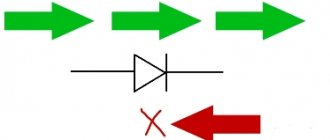
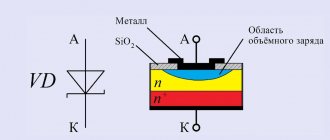
A standard diode is a component of the electrical network and acts as a pn junction semiconductor. Its structure allows current to pass through the circuit in only one direction - from the anode to the cathode (different ends of the part). To do this, you need to apply “+” to the anode and “-” to the cathode.
Note! Electric current in diodes cannot flow in the opposite direction, from the cathode to the anode.
Due to this feature of the product, if you suspect a breakdown, it can be checked with a tester or multimeter. Today there are several types of diodes in radio electronics:
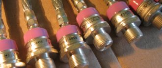
Types of diodes
- Light-emitting diode. When an electric current passes through such an element, it begins to glow as a result of the transformation of energy into a visible glow;
- protective or regular diode. Such elements in the electrical network act as a suppressor or voltage limiter. One of the varieties of this element is the Schottky diode. It is also called a Schottky barrier diode. Such an element, when connected directly, gives a low voltage drop. In Schottky, instead of a pn junction, a metal-semiconductor junction is used.
If ordinary parts and LEDs are used in the vast majority of electrical appliances, then Schottky ones are used mainly in high-quality power supplies (for example, for devices such as computers). It is worth noting that testing a conventional diode and a Schottky diode is practically no different, since it is carried out according to the same principle. Therefore, there is no need to worry about this issue, because the operating principle of both Schottky and conventional diodes is identical. Note! Here it is only worth noting that Schottkis in most cases are found double, located in a common building. Moreover, they have a common cathode. In such a situation, you can not solder these parts, but check them “on the spot”.
Schottky diode
Being a component of an electronic circuit, such semiconductor elements often fail. The most common reasons for their failure are:
- exceeding the maximum permissible direct current level;
- excess reverse voltage;
- poor quality part;
- violation of the device operating rules established by the manufacturer.
Moreover, regardless of the cause of loss of performance, failure can be directly caused by either a “breakdown” or a short circuit. In any case, if there is an assumption that the electrical network has failed in the semiconductor area, it is necessary to diagnose it using a special device - a multimeter. Only to carry out such manipulations you need to know how to check the diode using it correctly.
Testing and interchangeability
Schottky rectifiers can be tested in the same way as conventional semiconductors, since they have similar characteristics. You need to ring it in both directions with a multimeter - it should show itself in the same way as a regular diode: anode-cathode, and there should be no leaks. If it shows even a slight resistance - 2-10 kilo-ohms, this is already a reason for suspicion.
Checking a Schottky diode with a multimeter
A diode with a common anode or cathode can be tested like two ordinary semiconductors connected together. For example, if the anode is common, then it will be one leg out of three. We place one tester probe on the anode, the other legs are different diodes, and another probe is placed on them.
Can it be replaced with another type? In some cases, Schottky diodes are replaced with ordinary germanium diodes. For example, D305 at a current of 10 amperes gave a drop of only 0.3 volts, and at currents of 2–3 amperes they can generally be installed without radiators. But the main purpose of the Schottky installation is not a small drop, but a low capacity, so replacement will not always be possible.
As we see, electronics does not stand still, and further applications of high-speed devices will only increase, making it possible to develop new, more complex systems.
How is the check carried out?
After we have figured out the semiconductors of the electrical circuit and the purpose of the device, we can answer the question “how to check the diode for serviceability?” The whole point of checking diodes with a multimeter is their one-way electrical current carrying capacity. If this rule is observed, the electrical circuit element is considered to function correctly and without failures. Conventional diodes and Schottky diodes can be easily tested using this device. To check this semiconductor element with a multimeter, you need to do the following manipulations:
Examination
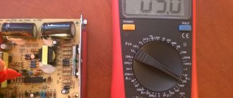
- you need to make sure that your multimeter has a diode test function;
- If such a function is available, we connect the probes of the device to the side of the semiconductor from which the “ringing” will be carried out. If this function is missing, then use the switch to switch the device to 1 kOhm. You should also select the mode for measuring resistance;
- the red wire of the measuring device must be connected to the anode end, and the black wire to the cathode end;
- after this, you need to observe changes in the forward resistance of the semiconductor;
- we draw conclusions about the presence or absence of voltage
The unit can then be switched to check for leaks or high circuits. To do this, you need to change the location of the diode output. In this state, it is also necessary to evaluate the obtained values of the device.
Checking the LED with a battery
To test the LED using a battery, you need to assemble the circuit according to the diagram.
Diagram for checking LED1 from a 9V battery.
On the diagram:
- LED1 – device being tested.
- 9V – power source (battery with a voltage of 9V).
- VAΩ is a measuring device for measuring V – voltage, A – current, Ω – resistance, AVOmeter or multimeter. In the diagram it works in voltage measurement mode.
- R1 is a current limiting resistor.
- R2 is a variable resistor that sets the brightness of the LED.
Resistor R2 on the multimeter sets the rated operating current. A working LED element produces light. Faulty - no light.
The term “multimeter” is a transliteration of the international name “Multimeter”. Derived from the terms Multi – many and meter – to measure. It has the names “tester”, “AVOmeter” - from Ampere-Volt-Ohmmeter.
A modern multimeter is a universal measuring device with a digital display.
One of the types of multimeters.
Another name for the device is “tester” - a Cyrillic transliteration of the international term tester - tester, verifier, tester.
Checking the diode bridge
Diode bridge
Sometimes there is a situation when you need to check the functionality of a diode bridge. It looks like an assembly consisting of four semiconductors. They are connected in such a way that the alternating voltage supplied to two of the four soldered elements becomes direct. The latter is removed from the other two terminals. As a result, the alternating voltage is rectified and converted into constant voltage.
Essentially, the principle of verification in this situation remains the same as described above. The only feature here is the determination of which output the measuring device will be connected to. There are four connection options that you should call:
- conclusions 1 – 2;
- conclusions 2 – 3;
- conclusions 1 – 4;
- conclusions 4 – 3;
By checking each output, you will get four results. The obtained indicators should be evaluated according to the same principle as for an individual semiconductor.
Significant characteristics of protection diodes
- Utrial _ (breakdown)
The voltage value at which the diode opens and the potential is transferred to the common wire. An additional synonymous designation is VBR.
Maximum reverse leakage current. It has a small value, measured in microamps, and the functionality of the device practically does not depend on it. Additional designation - IR.
The value is an indicator of constant reverse voltage. V.R.W.M.
The highest value for limiting impulse voltage. VCL, VCmax.
The highest value of the peak pulse current. Otherwise, this is an indicator of the greatest strength of the current pulse that is safe for the protective diode. For the most effective limiting zener diodes, this value can be hundreds of amperes. IPP.
Indicator of the highest value of permissible pulse power. Unfortunately, this parameter is extremely dependent on the pulse duration.
Fig. 2 VA characteristics of the protective diode
The power level of protection diodes is not the same. However, if the suppressor does not have enough initial data on this parameter, it can easily be combined with one or more semiconductors, which will have a positive effect on the overall power level.
Analyzing the results
When checking diodes (regular and Schottky) with a multimeter, you will get a certain result. Now we need to understand what it could mean. Signs that indicate the health of the semiconductor include the following:
- when connecting a part of the electrical circuit to the device, the latter will output the value of the available direct voltage in this element;
Note! Different types of diodes have different voltage levels, which is why they differ. For example, for germanium products this parameter will be 0.3-0.7 volts
- when connected in the opposite way (the probe of the device to the anode of the product), zero will be recorded.
Reverse check
If these two indicators are met, then the semiconductor is working adequately and the cause of the failure is not in it. But if at least one of the parameters does not correspond, then the element is considered unusable and must be replaced. In addition, it should be borne in mind that it is not a breakdown, but a “leakage” that is possible. This unpleasant defect can appear during long-term use of the device or poor-quality assembly. If there is a short circuit or leakage, the resulting resistance will be quite low. Moreover, the conclusion must be made based on the type of semiconductor. For germanium elements, this indicator in this situation will range from 100 kilo-ohms to 1 mega-ohm, for silicon - thousands of mega-ohms. For rectifier semiconductors, this figure will be many times higher. As you can see, it is not so difficult to assess the performance of semiconductors in any electrical device on your own. The above principle is suitable for testing diode elements of various types and types. The main thing in this situation is to correctly connect the measuring device to the semiconductor and analyze the results obtained.
Operating principles
The protective diode has a specific VA characteristic characterized by nonlinearity. Provided that the size of the pulse amplitude is greater than permissible, this will entail a so-called “avalanche breakdown”. In other words, the amplitude size will be normalized, and all excess will be removed from the network through a protective diode.
Fig. 1 Protective diode - principle of operation of a semiconductor
The operating principle of a TVS diode assumes that until a danger occurs, the diode fuse in no way affects the device itself or its functional properties. Thus, it should be noted that another name for the protective diode is emerging - an avalanche diode.
There are two types of limiting zener diodes:
Protective diode, bidirectional, suitable for operation in alternating current networks.
Applicable only for networks with direct current, since they have a unidirectional operating mode. The method of connecting an asymmetrical protective diode does not correspond to the standard. Its anode is connected to the negative bus, and its cathode is connected to the positive bus. The position turns out to be conditionally inverted.
The coding of protective diodes classified as symmetrical includes the letters “ C ” or “ CA ”. Single-ended diode fuses have a color-coded stripe on the cathode terminal side.
The housing of each protective diode is also equipped with a marking code that displays all significant parameters in a compressed form.
If the input voltage level of the diode increases, the zener diode will reduce its internal resistance over a very short period of time. The current strength at this moment, on the contrary, will increase, and the fuse will blow. Since the protective diode almost instantly, the integrity of the main circuit is not compromised. In fact, a quick response to excess voltage is the most important advantage of a TVS diode .
How to choose the right protective diode?
Applying the following rules will help you avoid problems with the purchase of a protective diode. To avoid making a mistake in your choice, you must:
- Decide on the type of voltage (will it be variable or constant?);
- TVS will need unidirectional or bidirectional;
- Find out what the rated voltage level is on the line that will need to be protected;
- Inquire about the maximum value of Ilim. and Ulimit.max. under load conditions;
- Determine the upper and lower temperature limits at which the device will operate;
- Decide how the element will be mounted (surface/using holes);
- Based on all the identified data, it is necessary to decide on the appropriate series and optimal diode option.
In addition, you need to consider:
- How high is the reverse voltage of the diode (it must exceed the rated voltage of the circuit; if this moment is not taken into account, then the diode will “turn on” even without any reason);
- Level Ulimit. must be less than Umax. on the line that needs to be protected;
- That even if the diode is selected in accordance with all needs, its operation still needs to be checked over the entire required temperature range;
- Make sure that the dimensions of the diode and other nuances allow for its adequate installation.
When the multimeter is ready, you need to connect it with probes to the suppressor terminals (positive-red with the anode, negative-black with the cathode). When this is done, the display of the testing device will display a number indicating the threshold voltage of the diode fuse being tested. When changing the polarity of the connection, an infinite resistance value should be displayed. If everything turned out this way, then the element is working.
If a leak is detected during a pole change, we can talk about the dysfunction of the element and the need to replace it. Similarly, you can check the protective diode of a car generator.
PulseGuard - low-capacity chip suppressors for ESD protection
Electrostatic discharge (ESD) is a type of electrical transient that poses a serious threat to sensitive electronic circuits. The most common cause of ESD is friction between dissimilar materials.
ESD interference potential can reach levels of up to 15,000 V, which can cause catastrophic damage to electronic components in a circuit.
PulseGuard® is a family of ESD suppressor chips developed by Littelfuse for low voltage signal circuits. These arresters, made from polymer composites, have extremely low capacitance (<0.12 pF), low leakage current (<1 nA) and fast response time (<1 ns), making them ideal for use in high-speed data transfer applications : IEEE1394, USB, HDMI, DVI, eSata, Ethernet.
These suppressors provide reliable protection against ESD without distorting the signal passing along the protected lines. PulseGuard® suppressors are selected when the application requires ESD protection only (IEC 61000-4-2), or data and signal line protection only, or where the application has stringent requirements for low introduced stray capacitance.
The PulseGuard® family consists of the PGB1 and PGB2 series. Suppressors of sizes 0201 and 0402 are a single bidirectional TVS diode with an operating voltage of 12 V; for size 0603 this parameter is 24 V. Suppressors in the SOT-23 package are designed for an operating voltage of 24 V and consist of two symmetrical (bidirectional) TVS diodes .
The low capacitance of PulseGuard® suppressors allows for excellent response speed and insertion loss performance up to 10 GHz.
•••
Basic qualities of TVS diodes
- Ability to function stably under reverse voltage conditions;
- Reverse currents should actually be minimal so as not to affect the functionality of the device as a whole.
- The reaction speed to a quick critical impact should be at the minimum possible level.
- The maximum possible indicator for the level of power dissipation.
But, as a result, it is necessary to recognize that the fulfillment of one condition often entails a violation of another.
In addition, the TVS diode, in principle, cannot be considered an ideal protective limiter. For example, suppressor protective diodes in the “off” position can be characterized by fairly large reverse currents. Further, abruptness when changing modes is disapproved. The biggest problem is that in the limiting mode the voltage level is directly dependent on the current strength.
It must be remembered that all diode characteristics given by the manufacturer are valid only under specific temperature conditions. At higher temperatures, the permissible peak power and currents will decrease.
However, even despite such shortcomings, diode fuses still turn out to be better than instruments, devices and elements with a similar purpose .
Checking the photodiode
In a simple test, the reverse and forward resistance of a radio element placed under a light source is measured, after which it is darkened and the procedure is repeated. For more accurate testing, you will need to take the current-voltage characteristic; this can be done using a simple circuit.
An example of a circuit for measuring current-voltage characteristics
To illuminate the photodiode during testing, you can use an incandescent lamp with a power of 60 W or more as a light source or bring the radio component to a chandelier.
Photodiodes sometimes have a characteristic defect, which manifests itself in the form of a chaotic change in current. To detect such a malfunction, it is necessary to connect the element under test as shown in the figure and measure the reverse current for a couple of minutes.
Testing for "creep"
If during testing the current level remains unchanged, then the photodiode can be considered working.
Testing without desoldering.
As practice shows, it is not always possible to test a diode without desoldering it when it is on the board, like other radio components (for example, a transistor, capacitor, thyristor, etc.). This is due to the fact that elements in the circuit may produce an error. Therefore, before checking the diode, it must be desoldered.
Basic qualities of TVS diodes
- Ability to function stably under reverse voltage conditions;
- Reverse currents should actually be minimal so as not to affect the functionality of the device as a whole.
- The reaction speed to a quick critical impact should be at the minimum possible level.
- The maximum possible indicator for the level of power dissipation.
But, as a result, it is necessary to recognize that the fulfillment of one condition often entails a violation of another.
In addition, the TVS diode, in principle, cannot be considered an ideal protective limiter. For example, suppressor protective diodes in the “off” position can be characterized by fairly large reverse currents. Further, abruptness when changing modes is disapproved. The biggest problem is that in the limiting mode the voltage level is directly dependent on the current strength.
It must be remembered that all diode characteristics given by the manufacturer are valid only under specific temperature conditions. At higher temperatures, the permissible peak power and currents will decrease.
However, even despite such shortcomings, diode fuses still turn out to be better than instruments, devices and elements with a similar purpose .
Checking the integrity of the protective diode
Checking the integrity of the protective, as well as the rectifying (including power) diode, is carried out with a multimeter (as an option, you can use an ohmmeter). The device can be used for this purpose only in dialing mode.
Fig 3 Checking the protective diode
When the multimeter is ready, you need to connect it with probes to the suppressor terminals (positive-red with the anode, negative-black with the cathode). When this is done, the display of the testing device will display a number indicating the threshold voltage of the diode fuse being tested. When changing the polarity of the connection, an infinite resistance value should be displayed. If everything turned out this way, then the element is working.
Power determination
The operating power of the LED is necessary for its correct connection to the operating circuit of any device. Many people are faced with the problem of how to find out the power of an LED without markings on the case or packaging. There are 2 ways to determine this parameter.
Visually
LEDs are produced in a variety of sizes and colors. By color and size you can find out the power of this part:
- Small infrared ones operate at a voltage of 20 mA, with a power of less than 2 Watts.
- Red ones have an operating voltage of up to 15 mA with a power of up to 1.7 W.
- Small yellow ones have a power of up to 2.2 W.
- Greens from 1.9 to 3.6 W.
- Blue from 2.5 to 3.6 W.
- Violet from 2.5 to 4 W.
- Large yellow ones operate from voltages up to 300 mA, have a power of 2.2 Watts, with radiator cooling.
- Large white or pink ones consume voltage up to 20 mA, with a power of up to 3.6 Watts.
You can determine the size of the LED using a regular caliper. Parts from 3 to 10 mm are considered small.
Multimeter
Determining the power of an LED with a multimeter is not difficult if you connect all the components according to the diagram. Next you will need:
- Find the cathode of the LED and connect one end of a 500 ohm resistor to it.
- Connect the “+” output from the power supply to the anode.
- Connect the negative from the power supply to the second end of the resistor.
This circuit will require a power supply with a voltage regulator. Further:
- Using the regulator, raise the voltage and measure it before and after the element being tested. It should be the same.
- Raise and measure the voltage again.
- Repeat adjusting and measuring voltage until a difference appears.
- At this point, you need to remember the last value in volts.
- Replace the 500 Ohm resistor with a similar element with a resistance of 10 Ohms.
- Raise the voltage to the calculated value.
- Switch the multimeter to ammeter mode.
- Measure the power.
This method does not require desoldering from the circuit if the LED is already connected to the circuit. The main thing is to correctly determine the polarity of the connection.
Significant characteristics of protection diodes
- Utrial _ (breakdown)
The voltage value at which the diode opens and the potential is transferred to the common wire. An additional synonymous designation is VBR.
Maximum reverse leakage current. It has a small value, measured in microamps, and the functionality of the device practically does not depend on it. Additional designation - IR.
The value is an indicator of constant reverse voltage. V.R.W.M.
The highest value for limiting impulse voltage. VCL, VCmax.
The highest value of the peak pulse current. Otherwise, this is an indicator of the greatest strength of the current pulse that is safe for the protective diode. For the most effective limiting zener diodes, this value can be hundreds of amperes. IPP.
Indicator of the highest value of permissible pulse power. Unfortunately, this parameter is extremely dependent on the pulse duration.
Fig. 2 VA characteristics of the protective diode
The power level of protection diodes is not the same. However, if the suppressor does not have enough initial data on this parameter, it can easily be combined with one or more semiconductors, which will have a positive effect on the overall power level.
A TVS diode can act as a zener diode. But first you need to check its maximum power dissipation and dynamic current at Imax. and Imin.
Operating principles
The protective diode has a specific VA characteristic characterized by nonlinearity. Provided that the size of the pulse amplitude is greater than permissible, this will entail a so-called “avalanche breakdown”. In other words, the amplitude size will be normalized, and all excess will be removed from the network through a protective diode.
Fig. 1 Protective diode - principle of operation of a semiconductor
The operating principle of a TVS diode assumes that until a danger occurs, the diode fuse in no way affects the device itself or its functional properties. Thus, it should be noted that another name for the protective diode is emerging - an avalanche diode.
There are two types of limiting zener diodes:
Protective diode, bidirectional, suitable for operation in alternating current networks.
Applicable only for networks with direct current, since they have a unidirectional operating mode. The method of connecting an asymmetrical protective diode does not correspond to the standard. Its anode is connected to the negative bus, and its cathode is connected to the positive bus. The position turns out to be conditionally inverted.
The coding of protective diodes classified as symmetrical includes the letters “ C ” or “ CA ”. Single-ended diode fuses have a color-coded stripe on the cathode terminal side.
The housing of each protective diode is also equipped with a marking code that displays all significant parameters in a compressed form.
If the input voltage level of the diode increases, the zener diode will reduce its internal resistance over a very short period of time. The current strength at this moment, on the contrary, will increase, and the fuse will blow. Since the protective diode almost instantly, the integrity of the main circuit is not compromised. In fact, a quick response to excess voltage is the most important advantage of a TVS diode .
How to check without desoldering
In order to connect the multimeter probes to the connectors in the PNP block, you need to solder small fragments of a regular paper clip onto them. Between the wires on which the paper clips are soldered, for insulation, you can install a small textolite gasket and wrap it with electrical tape. Thus, we get a simple design and reliable adapter for connecting probes.
Next, you need to connect the probes to the legs of the LED without removing it from the product circuit. Instead of a tester, to check the LED diode, you can use one Krona battery, or several AA batteries. The connection is carried out in the same way, but instead of an adapter, you can use small alligator clips to connect to the battery outputs of the probes.
Let's look at a specific example of how to check an LED without desoldering it from the circuit.
Checking the integrity of the protective diode
Checking the integrity of the protective, as well as the rectifying (including power) diode, is carried out with a multimeter (as an option, you can use an ohmmeter). The device can be used for this purpose only in dialing mode.
Fig 3 Checking the protective diode
When the multimeter is ready, you need to connect it with probes to the suppressor terminals (positive-red with the anode, negative-black with the cathode). When this is done, the display of the testing device will display a number indicating the threshold voltage of the diode fuse being tested. When changing the polarity of the connection, an infinite resistance value should be displayed. If everything turned out this way, then the element is working.
If a leak is detected during a pole change, we can talk about the dysfunction of the element and the need to replace it. Similarly, you can check the protective diode of a car generator.
How to choose the right protective diode?
Applying the following rules will help you avoid problems with the purchase of a protective diode. To avoid making a mistake in your choice, you must:
- Decide on the type of voltage (will it be variable or constant?);
- TVS will need unidirectional or bidirectional;
- Find out what the rated voltage level is on the line that will need to be protected;
- Inquire about the maximum value of Ilim. and Ulimit.max. under load conditions;
- Determine the upper and lower temperature limits at which the device will operate;
- Decide how the element will be mounted (surface/using holes);
- Based on all the identified data, it is necessary to decide on the appropriate series and optimal diode option.
In addition, you need to consider:
- How high is the reverse voltage of the diode (it must exceed the rated voltage of the circuit; if this moment is not taken into account, then the diode will “turn on” even without any reason);
- Level Ulimit. must be less than Umax. on the line that needs to be protected;
- That even if the diode is selected in accordance with all needs, its operation still needs to be checked over the entire required temperature range;
- Make sure that the dimensions of the diode and other nuances allow for its adequate installation.
The protection diode is a guest of our review of semiconductors.
The power of interference affecting the voltage level in the device may vary. To counter high-energy pulses, it is possible to use gas dischargers and protective thyristors. To protect yourself from medium and low-power influences, protective diodes and varistors are more suitable.