A significant number of drive systems are used to naturally slow down engines when stopped. The time it takes to stop the rotor is measured solely by the inertial moment and the moment of resistance to rotation. Meanwhile, the operation of systems often requires reducing the stopping time of the motor shaft, and in this case, electrical braking of the electric motor seems to be a simple and effective solution. Compared to devices that use mechanical or hydraulic methods, electrical braking of motors has clear advantages in terms of stability of operation and cost-effectiveness of use.
Options for constructing electric brakes
Let's consider several options for braking motors electrically, which can be applied in practice. At the same time, we note the possibility of using braking mechanisms in relation to electric motors of different types. The list of braking techniques considered includes the following:
- countercurrent,
- DC input,
- electronically,
- supersynchronous speed,
- in other ways.
Main types of dynamic braking
Organizing a forced stop of an asynchronous motor using the electrical principle can be carried out in several ways:
- Electrodynamic. This is a classic option, in which two phases need to be short-circuited and transferred to DC power,
- Regenerative (generator). Characterized by the return of excess electricity to the network,
- Anti-inclusion. This option is implemented using a reverse circuit, that is, with the phases connected through a pair of magnetic starters,
- Self-excitation. By connecting a battery of capacitors to the stator windings.
Countercurrent braking principle
The motor is disconnected from the power supply, and while the rotor continues to rotate, it is reconnected in antiphase. Such a system creates an effective locking torque, usually higher than the starting torque.
Meanwhile, this effective braking torque must be quickly neutralized so that the engine does not rotate in the opposite direction after stopping. Several control and automation devices are used to ensure that the rotation of the electric motor shaft is slowed down until it stops completely:
- clutch stop sensors,
- centrifugal stop sensors,
- chronometric instruments,
- frequency relay,
- rotor voltage relay (for wound-rotor motors), etc.
Braking a squirrel-cage motor
Before choosing a countercurrent system for an asynchronous motor with a short-circuit rotor, it is important to ensure the resistance of the motor to the countercurrent method, taking into account the required load.
In addition to mechanical stress, this process exposes the rotor to high thermal loads as the energy generated by each operation is dissipated in the rotor body.
The thermal stress in the counterflow is three times greater than when the rotation speed increases. Here the peaks of current and torque are noticeably higher when compared with the starting moment.
The principle of the countercurrent technique on the electric motor circuit in order to quickly slow down and then stop. On the left is the normal operating cycle. On the right is the deceleration and stopping cycle
Therefore, to ensure a smooth stop of the engine by the countercurrent system, as a rule, a resistor is installed in series with each stator phase. Thanks to this addition, when switching, the torque and current are reduced to values equal to those noted on the stator in starting mode.
However, the countercurrent braking system has a number of serious disadvantages. Therefore, this method for asynchronous motors with a squirrel-cage rotor is used in rare cases and mainly on low-power motors.
Countercurrent braking on wound-rotor motors
To limit the current and torque before the stator is switched to countercurrent running, the rotor resistors used for starting are essential.
In this case, an additional resistive braking section should be periodically added. With the correct value of the rotor resistor, adjusting the braking torque to the required value is easy.
The moment of current switching gives the rotor voltage almost twice as much as when the rotor is at rest, which sometimes requires special measures for insulation.
The principle of countercurrent electrical blocking on motors with wound rotor. On the left is normal operation. Right - deceleration and stop
As with power motors, the rotor circuit produces a significant amount of energy. All released energy is completely dissipated in resistors (except for small losses).
The engine can be stopped automatically by one of the above mentioned control devices. For example, using a voltage or frequency relay in the rotor circuit. Using a counterflow circuit, it is possible to maintain the driving load at a moderate speed.
However, the characteristic is extremely unstable (significant fluctuations in speed relative to small changes in torque).
Electrical energy recovery and its use
The traditional way to get rid of excess energy released in frequency converters during braking of the induction motors they control was to dissipate it in the form of heat on resistors.
Braking resistors were used wherever there was high load inertia, for example in centrifuges, electric vehicles, load stands, etc. This solution was necessary to limit the maximum voltage at the terminals of the converters in braking mode. Otherwise, the frequency converters would fail, because it would be impossible to control the acceleration and deceleration parameters.
Braking resistors did not burden the equipment economically, but they invariably entailed some inconveniences. Resistors are oversized, get very hot, and need protection from moisture and dust. And all this is connected only with the fact that it is necessary to waste energy, for which the enterprise pays money, and the money is not small, especially if we are talking about large-scale production.
In summer, additional heating of the surrounding air is especially undesirable, because the technological equipment is already heated by warm air, and then there are resistors heated to 100 degrees and above. Additional ventilation is needed - again costs.
But there is another way. Why waste energy? You can return it back to the network, and thus save energy costs. This is where energy recovery systems .
Of course, today's frequency converters greatly reduce the electricity consumption of equipment by optimizing the way they power the motors of various process equipment, and this saves resources. But the use of recovery increases savings even more. Energy may not be dissipated on resistors during braking, but returned to the network taking into account the current network parameters.
Today, leading manufacturers of industrial mechanisms and equipment are already implementing such systems in electric transport: for trolleybuses, electric trains, escalators, trams, and finally - for electric cars.
How does the recovery system work? The AC source powering a motor or other installation must be able to accept energy back. For this purpose, instead of a conventional rectifier, a converter with pulse width modulation is used. Such a converter is able to direct power flows both from source to consumer and from consumer to source. This path allows you to bring the power factor to unity.
DC injection braking
This option is used on motors with wound and squirrel-cage rotors. Compared to a countercurrent system, the cost of using a rectified current source is offset by fewer resistors.
Thanks to electronic speed controllers and starters, this method of braking asynchronous electric motors seems to be quite economical.
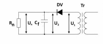
Stopping principle by DC injection. This system requires a constant voltage source to operate. Voltage requirements are not critical
The technique involves disconnecting the stator windings from the network and supplying rectified current to the windings. The passage of rectified current through the stator windings is accompanied by the formation of a fixed flux in the air gap between the rotor and the stator ring of the motor.
To achieve a value of this flux that can provide proper braking, the current must be approximately 1.3 times the rated current. The excess heat loss inevitably caused by this slight excess is usually compensated by a temporary pause after stopping the motor.
Criteria for applying the DC injection method
Since the current value depends on the resistance of the stator winding, the voltage at the rectified current source is low. Typically the source is a rectifier or speed controller circuit.
These rectified current sources must be adapted to the transient voltage surges that occur on the windings when disconnected from the AC power source.
The rotor movement here should be considered as sliding relative to a field fixed in space. The behavior of the motor is similar to that of a synchronous generator with unloading on the rotor. Therefore, the differences in the characteristics obtained during braking by introducing a rectified current are important, compared to a countercurrent circuit:
- Less energy is dissipated in the rotor resistors or in the rotor body. The process is equivalent to the mechanical energy released en masse during movement. The only power consumed from the network is the stator excitation.
- When the load is not controllable, the motor will not start in the opposite direction.
- If the load is controllable, the system operates continuously and keeps the load at low speed. That is, a deceleration factor is achieved, rather than complete braking. The performance is much more stable than that of a counterflow system.
On wound-rotor motors, the torque characteristics depend on the choice of resistors.
Option of braking resistors: 1 - heating sensor; 2 - metal shunt; 3 - high-temperature conductor; 4 - wire resistive element; 5 - temperature block; 6 - body
On squirrel-cage motors, the system allows you to easily adjust the braking torque of the electric motor, influencing the DC energy. However, the braking torque remains low if the engine is running at high speeds.
Regenerative braking in electric vehicles: what it is and how it works
The term “recovery” itself has been known for a long time and implies the possibility of partial return of used energy (heat, water, gases) for the purpose of its reuse. In this sense, regenerative braking also implies the process of returning part of the expended energy.
What is regenerative braking?
When choosing an electric vehicle, one of its most important parameters is the range on one charge. Manufacturers of electric cars are conducting active research and introducing new developments that make it possible to increase the range of an electric car on a single charge. Regenerative braking, as one of the possibilities for partially restoring battery charge, is an important nuance when choosing an electric car.
In a few words, regenerative braking in electric vehicles can be described as the process of obtaining energy during braking of a car, i.e. in fact, this is recharging the battery of an electric car while driving.
Principle of operation
To understand how the regenerative braking system works, it is necessary to remember that every moving body has kinetic energy. When braking a car with an internal combustion engine, this energy is consumed during contact between the brake pads and brake discs, erasing them, i.e. just “to nowhere.” Electric vehicles take a more careful approach to energy use. The recovery process is presented here as follows:
- When braking begins, the electric motor changes its operating mode: instead of being powered by the battery, it begins to work as a generator, generating energy. At this moment, currents of opposite directions arise in the rotor and stator windings.
- The vehicle speed decreases due to the fact that a braking torque appears on the electric motor shaft.
- The kinetic energy available before braking begins is transformed into electrical and thermal energy.
- The additional electricity that appears is supplied to the battery, thereby increasing its charge.
Electronic and super-synchronous engine braking
The effect of electronic braking is achieved relatively simply by using a speed controller equipped with a braking resistor. An asynchronous motor acts as a generator. Mechanical energy is dissipated in the limiting resistor without increasing losses in the motor itself.
The braking effect occurs when the motor reaches the top of the synchronous speed and moves to higher values. Here the asynchronous generator mode is actually initiated and the braking torque develops. The resulting energy losses are restored by the power grid.
A similar operating mode occurs on lift motors when lowering loads at rated speed. The braking torque is completely balanced by the torque from the load.
Due to this balance, it is possible to brake not by reducing the speed, but by bringing the engine into operation at a constant speed.
For the operation of wound-rotor motors, all or part of the rotor resistors must be short-circuited so that the motor does not develop movement significantly above the rated speed.
The supersynchronous system appears to be functionally ideal for limiting movement under load because:
- The speed remains stable and is practically independent of torque,
- Energy is recovered and renewed on the grid.
However, supersynchronous braking of electric motors only maintains one rotation speed, typically the rated rotation. Frequency-controlled motors use supersynchronous circuits, due to which the shaft rotation speed changes from a high value to a low value.
Supersynchronous braking is easily achieved by using an electronic speed controller, which automatically activates this system when the frequency is reduced.
Other braking systems
Rarely, but still there are single-phase braking systems. This technique powers the motor between two mains phases and connects the unoccupied terminal to one of the other two mains connections.
Stopping option by simple reverse switching - reversing the rotation field formed by the stator windings
The braking torque is limited to 1/3 of the maximum motor torque. This system cannot stop the engine at full load.
Therefore, this scheme is traditionally complemented by a countercurrent method. The single-phase blocking option is characterized by significant imbalance and high losses.
Electric motor braking is also used by weakening eddy currents. The principle at work here is similar to that used on industrial vehicles in addition to mechanical braking (electrical gearboxes).
Mechanical energy is dissipated in the speed reducer. Slowing down and stopping the electric motor is controlled by simply energizing the winding. A significant disadvantage of this method is a significant increase in inertia.
Recommended files
FREE
Maran Software Engineering
Software engineering
Technical task
Requirements Engineering and Software Specification
Design of cantilever pump K25/32
Blade hydraulic machines
Innovative modes “Market traction and technological push”
Management theory
FREE
Ovsyannikov B.V., Borovsky B.I. — Theory and calculation of power units for liquid rocket engines
Liquid rocket engines (LPRE)
Space flights and engine types
Research work
those. .
In the motor mode S>0 and the components and are positive, and the inductive current is.
In generator mode S<0. In this case, it does not change its sign, but the current changes sign (φ2 = 1800). Physically, this is explained by the fact that the field rotates relative to the rotor compared to the motor mode in the opposite direction. In this case, the sign of the EMF also changes.
The engine switches to generator mode. The electromagnetic torque also changes its sign and it becomes braking. Consequently, the engine already operates as a generator in parallel with the network, and supplies electrical energy while consuming reactive power for excitation. It should be noted that an asynchronous machine, both in motor and generator modes, consumes reactive energy from the network, i.e. generator mode is possible only if there is a network that is capable of supplying the asynchronous generator with the reactive power necessary to create a magnetic field.
Often the characteristics corresponding to the generator slip will be located in the second square (II). Therefore, this mode will correspond to slip values from “0” to “-”. In this mode, as can be seen from the formula for the critical moment, the critical moment has a larger value than in the motor mode.
Braking with energy recovery into the network is used in lifting and transport devices when lowering heavy loads. Under the influence of a descending load, the asynchronous machine begins to rotate at a speed. In this case, the machine goes into generator mode and begins to create braking torque. The steady equilibrium state will correspond to the point of intersection of the mechanical characteristics of the engine and the static torque line. In this case, the equality M>Mc is established and the load will descend at a steady speed.
To do this, in order to ensure normal braking release of the load, the static torque should not exceed the critical torque of the machine in generator mode.
If there is a reactive element
, static torque, then braking with energy recovery into the network is possible only if an asynchronous motor is used with switching the number of pole pairs.
Let us assume that the stator windings are connected in such a way that they provide fewer pole pairs, i.e. the engine runs at point A, at highest speed
If the windings are switched to a smaller number of pole pairs p2, then the motor will start working at point B on characteristic 2 passing through point
The motor rotation speed during switching will be greater than the synchronous speed corresponding to the new number of poles, i.e.
.
The machine will switch to generator mode. In Fig. 4.10, the area with energy transfer to the network corresponds to the VSD section of the mechanical characteristic.
This process is used (takes place), for example, in the drives of metal-cutting machines when switching engine speeds.
Analytical method for calculating starting rheostats
With the analytical method, the resistance of the starting rheostat resistors is calculated using the formulas:
In these expressions, λ = I1/I2 is the ratio of the initial starting current I1 to the switching current I2 . When the engine is running from an adjustable voltage converter, there is no need for a starting rheostat, since the engine can be started from any reduced voltage value on the armature winding in accordance with the permissible value of the initial starting current.
