Good afternoon
Tell me what is the technology for producing cable couplings. The fact is that recently, while making a hole in the ground for a support, I came across some kind of cable, apparently a connection, and, naturally, accidentally damaged it.I examined the damage - the wires seem to be intact, but the insulation is damaged. I heard that a good fine could be imposed for this, so I didn’t call anywhere. In general, there is an urgent need to patch up the gap and hide traces of activity while “the wind blows without stones.”
Work to restore cable integrity
Reply to reader
Welcome, stranger. Yes, it’s not for nothing that they say that it is impossible to change the people! The electricians of our site, over the years of their work, have more than once encountered homemade couplings, and they have never been seen before. If you think about it, you can organize a full-fledged exhibition.
All this, of course, is lyrics, so let’s talk about serious things step by step.
Type of damaged cable
First of all, you need to understand which cable you are dealing with. There are several options:
- A high-voltage power cable is a less likely option, since the voltage inside such a conductor exceeds 6 kV. The diameter of such cables ranges from 40 to 70 mm, and the cores inside them will be as thick as a finger, covered with a thick layer of insulation. It is not easy to break such a cable, but if this happens, then you would not be able to help but notice the impact, akin to a decent explosion.
- Power low-voltage electrical cable - the word low-voltage can be a little confusing, since the fact that in the concept of electricians low voltage means 220 or 380 Volts, which can be enough to cause death. The diameter of such cables is quite different and can be either 20 or 80 millimeters.
Danger! You will not be able to repair the power cable yourself, except perhaps a low-voltage one. And then you need to be sure that there is no voltage and it will not appear during installation of the coupling!
- Communication cables are low current . Their diameter can be from 5 to 60 mm. It is worth knowing that cables whose thickness is more than 40 mm are not laid directly into the ground, but are pulled through the telephone sewer. The peculiarity of such cables is that the number of cores in it can reach several hundred, which actually means that self-repair is impossible.
- Fiber optic lines are a separate group . Their peculiarity is that they have very strong armor, so causing damage to them is quite problematic. The diameter of such cables is 10-20 mm. You can’t even dream of repairing such lines yourself.
You can distinguish power and communication cables by their appearance. In the case of the former, polyvinyl chloride or paper is used for insulation, and the cores themselves are made of aluminum, although there are exceptions.
Others are characterized by polyethylene insulation and copper conductors. We won’t describe how to distinguish insulation materials, but you can watch the video or search for information on the Internet.
Couplings with insulation made of heat-shrinkable tubing
Installation of heat-shrinkable couplings on cables is very simple, since the presence of plastic elements greatly simplifies the entire process of connecting wires of cable fragments. The time required for installation in this case is approximately two times less than in the case of other connecting elements.
When the temperature is raised to 150 degrees using a gas burner or a hair dryer, polymer materials contract strongly and grasp the elements being pressed quite well, covering them 100%. Air masses from all cavities are released during this process through hot polymer material. As the heated material cools, it firmly adheres to the fragments of the power line and reliably envelops them. The service life of such switching can reach 25 years.
Heat-shrinkable sleeve
Return to content
Let's start repairing the line
Let’s say right away that depending on the type of cable and the nature of the damage it received, various repair methods can be used: installation of cable end joints, installation of internal cable joints (connectors). The solutions differ in the structure, size and operating voltage of the line.
Interesting to know! Sometimes a casing for the cable coupling is additionally installed in order not only to protect the connection from mechanical damage, but also to protect against fires and explosions when it comes to high-voltage lines.
Let's look at the most common options that you can use for DIY repairs.
Repairing scratches and cuts
Most often, the cable is not completely cut when damaged, but its external and possibly internal insulation suffers. To carry out such repairs you will need: mastic for cable couplings (bitumen), 3-5 centimeter polyethylene tape (you can cut a regular packaging tight bag), rags, a gas blowtorch (can be heated over a fire, but it takes a long time).
We perform the following actions:
- Heat the mastic thoroughly in an iron container until liquid.
Attention! Do not use white spirit at the same time as heating, as its vapors are very flammable. Better wait a little.
- The dimensions of the cable sleeve will be 15-20 centimeters on both sides of the cut, so release the required length of cable from the ground and clean it well and wipe it dry with rags.
- Next, using a wooden stick, mastic is applied to the desired part of the cable.
- Until the mass hardens, it is tightly covered with pre-prepared polyethylene tape.
- The squeezed out mastic is smoothed out.
- Additionally, the top of the polyethylene can be coated with a layer of bitumen.
The cost of such repairs is minimal, since all materials can be dug up in any garage.
Such repair work using factory products can be performed by:
- Welding using a special tape made of polyethylene or fiberglass.
- Heat shrinks – XAGA couplings, used in whole or in part.
Features of the design and installation of couplings for cables made of cross-linked polyethylene for 10 kV
Couplings are devices that serve to connect cable and wiring elements together. These types of couplings are widely used to prevent wiring elements from damage caused by mechanical stress, in order to protect the wiring from corrosion and moisture ingress. Couplings are used when installing various types of wires. Connectors for 10 kV cross-linked polyethylene cables have their own design and functional features, caused by the unique nature of the types of cables for which they are intended to connect.
Insulation based on cross-linked polyethylene has a number of features. First of all, it should be noted that this type of insulation is highly resistant to temperature influences. This results in cables being operated at temperatures that are higher than those typical for cables with other types of insulation. This imposes certain additional requirements on couplings that are intended for use with this type of wiring.
Couplings used at a voltage of 10 kV have three sealing circuits that ensure reliable connection:
- sealant that fills the interfacial space;
- internal heat-shrinkable casing;
- outer casing.
Before installing the wiring, you should clarify the type of metal screen that is used on the XLPE insulated cable being installed. The standard equipment includes a copper wire screen. However, other types of shielding are also possible. The type of coupling for connecting cables should be selected based on this feature of the wiring design.
When installation work is carried out, great attention should be paid to ensuring that the shielding remains intact - the shield shells should not be allowed to break off, since when it is mounted to the coupling, a decrease in the cross-sectional area of the wire may occur, which will affect the quality of the connection.
Typical mistakes that often occur when installing couplings.
Connectors for 10 kV cross-linked polyethylene cables have a number of features that lead to the fact that defects may arise during electrical installation, leading to various defects that threaten the proper operation of the wiring. The most common mistakes when installing couplings are:
1. Failure to comply with the rules for organizing the installation site. The place where the coupling will be installed must be equipped in such a way as to minimize the likelihood of dirt and moisture getting into it.
2. Poor quality connection of the cable coupling. Before installation, you should make sure that the connector and sleeve have the same cross-section and that the sleeve is designed for the type of core used in the cable.
3. Violation of tightness. When shrinking the outer casing, additional windings should be used. When the coupling is placed in a cable route or trench, it must be inspected again for damage.
Connectors for single-core cable made of cross-linked polyethylene
1PST010 can be used to connect various cables and are distinguished by the high quality of the composite materials used for their manufacture.
Connecting couplings for a three-core cable made of cross-linked polyethylene
3PTS-10 have tubes to equalize the electric field strength, which ensures reliable operation of high-voltage couplings.
3.1. Installation of straight coupling
3.1.1. In accordance with section 11 of table. 11.1 part P of the “Guidelines for the construction of linear structures of local communication networks”, the cable is cut. The polyethylene shell is removed along with the screen.
3.1.2. A fiber protective plate is inserted under the polyethylene shell (Fig. 3.1).
Rice. 3.1. Installation of a fiber protective plate.
3.1.3. When installing a cable with a capacity of up to 200 pairs, two longitudinal parallel cuts 25 mm long are made on the cable sheath above the fiber protective plate at a distance of 15 mm from each other (Fig. 3.2).
Rice. 3.2. Longitudinal cuts on the polyethylene sheath of the cable.
3.1.4. Using a knife and pliers, the cut out section of the shell along with the screen is bent upward, perpendicular to the cable. Using an awl, a hole with a diameter of 5-6 mm is made in the middle of the bent shell. A screw (M4) with a corrugated washer is inserted into the hole from the screen side (Fig. 3.3).
Figure 3.3. Installing a screw with a corrugated washer through a puncture in a bent shell.
3.1.5. After installing the screw, the bent section of the sheath is pressed against the cable core and secured with two layers of PVC insulating tape (Fig. 3.4).
Rice. 3.4. Securing the bent shell.
3.1.6. When installing a cable with a capacity of over 200 pairs, the screen is restored using a screen connector. It is recommended to use connector 4462 from ZM (Fig. 3.5).
Rice. 3.5. Connector 4462 from ZM.
To install it, one 25 mm long cut is made above the fiber protective plate.
The base of the connector is inserted into the cut under the shell with the screen, the upper part of the connector is installed and both parts are tightened with a nut.
3.1.7. Stepping back 10-12 mm from the cut of the polyethylene sheath on the belt insulation of the cable, make a nylon or cotton bandage. thread, remove the belt insulation tapes and begin splicing the cores.
3.1.8. Having finished splicing the cores, install the screen jumper on the screws of the screen connectors and secure it with a nut. Together with the jumper, the cable shield core is attached to the connector screw (Fig. 3.6).
Rice. 3.6. Fastening the screen jumper and the screen core of the cable.
3.1.9. On the stripped cable sheath and turns of PVC tape, close to the screen connector, apply MG 14-16 mastic in one layer with a slight overlap (Fig. 3.7).
3.1.10. A formwork made of polyethylene film is installed over the splice of cores. The formwork should equally cover the bands of mastic MG 14-16 (Fig. 3.8).
Rice. 3.7. Applying mastic MG 14-16.
Rice. 3.8. Installation of formwork made of polyethylene film.
3.1.11. The edges of the formwork are twisted into bundles towards the center, leaving a hole for filling the filler (Fig. 3.9).
Rice. 3.9. Formwork made of polyethylene film over the cable splice.
3.1.12. The beginning of the formwork in place of the applied mastic is wrapped with two layers of PVC tape. This is done in order to prevent the filler from leaking out (Fig. 3.10).
Rice. 3.10. Wrapping the formwork with PBX tape on the cable sheath over MG 14-16 mastic.
3.1.13. Cut off a corner on the bag with the Zakanit-N filling compound. Through a cut in the bag, the filler is squeezed into the formwork (Fig. 3.11).
Rice. 3.11. Filling the formwork with filler.
Filling is carried out until the filler completely covers the splices of the cores. Then the pouring is stopped, the paper clips are removed and the strands along the edges of the formwork are tightened until they meet at the top of the formwork. Then their joint is folded into an envelope (Fig. 3.12) and wrapped effortlessly around the joint. To prevent the formwork from falling apart, it is secured in the middle with two layers of PVC tape.
3.1.14. Next, the formwork is wrapped with 7-8 layers of adhesive tape “Scotch” (Fig. 3.13). Initially, the first 2-3 layers are produced without force, and all subsequent layers are produced with little force. During the winding process, the joint is formed by hand. You must try to ensure that the filler does not end up on one side of the joint, but evenly envelops it.
Rice. 3.12. Closing the formwork with an envelope.
Rice. 3.13. Wrapping the splice with Scotch tape.
3.1.15. Having finished wrapping the splice with Scotch tape on the left and right, 2-3 layers of PVC tape are wound on the ends of the formwork above the cable sheath (Fig. 3.14).
Rice. 3.14. Wrapping the formwork at the ends with PVC tape.
3.1.16. A polyethylene coupling is installed above the mounted and sealed joint. The joints of the coupling parts with each other and with the cable sheath are sealed using any permitted method.
In this “Installation Guide...”, a cold method using the domestic structural material “Armoplast” is proposed.
3.1.17. The surface of the coupling and cable sheath in the sealing areas is wiped with gasoline, and then carefully treated, first with a metal brush and then with sanding tape. The quality of installation largely depends on the cleanliness of the surface. On the coupling, the entire length of the cone is cleaned before moving to the cylindrical part. The middle joint is cleaned over an area of 100 mm (50 mm in both directions). The cable sheath is stripped at a distance of 60 mm from the end of the cone. After cleaning, the polyethylene crumbs and the abrasive of the sanding tape are removed with a clean rag.
3.1.18. Take a roll of LG-2 tape, unroll it and remove it from the paper by 10-15 mm and place it on the cable sheath close to the end of the coupling cone (Fig. 3.15).
Rice. 3.15. Start of winding of LG-2 tape.
Make a full turn of the tape with tension and continue winding it with 50% overlap over the entire cone of the coupling until the transition to the cylindrical part begins (Fig. 3.16). As the LG-2 tape is wound, the paper tape is torn off.
Rice. 3.16. Coupling cone with wound tape LG-2.
The LG-2 tape is wound in the same way on the second cone of the coupling.
3.1.19. Winding of the LG-2 tape at the middle joint begins near the bell of the coupling half (Fig. 3.17).
Rice. 3.17. Start of winding of LG-2 tape at the middle joint of the coupling.
Make a full turn of the tape with tension and continue winding it with 50% overlap, going into the bell and beyond (Fig. 3.18.). The total area with the wound tape on both sides of the end of the socket should be 50-60 mm.
Rice. 3.18. Winding LG-2 tape at the middle joint of the coupling.
3.1.20. The wound tape at all three joints is squeezed well by hand along the entire circumference. In Fig. Figure 3.19 shows a coupling on which all three joints are wrapped with LG-2 tape
Rice. 3.19. All three joints of the coupling are wrapped with LG-2 tape.
3.1.21. On top of the LG-2 tape at all three joints, three layers of adhesive PVC tape are wound with 50% overlap (Fig. 3.20).
In Fig. Figure 3.21 shows a coupling whose joints are wrapped with PVC tape.
Rice. 3.20. Winding PVC adhesive tape.
Rice. 3.21. Coupling joints with wound PVC tape.
3.1.22. After winding the PVC tape, wait approximately 15-20 minutes. At this time, the LG-2 tape is compacted under the influence of the tightening forces of the PVC tape wound on top.
3.1.23. After this time, put on protective gloves, open the sealed bag with “Armoplast” and begin winding the tape with 50% overlap from the middle of the coupling towards one of the extreme joints, and then back towards the middle joint, then through it to the other extreme joint and back to the average (Fig. 3.22). On large couplings, the tape can be wound on its cylindrical part (but not at the joints) with a 5% overlap.
It should be remembered that the Armoplast tape remains in an elastic state for 10-15 minutes after depressurization of the bag, then the hardening process begins. Taking this into account, you should work as quickly as possible, without taking breaks.
At the transition from the cylindrical part of the coupling to the cone, the tape should be twisted, as shown in Fig. 3.23.
Rice. 3.22. Winding “Armoplast” tape.
Rice. 3.23. Twisting of the Armoplast tape at the transition of the cylindrical part of the coupling to the cone.
At the extreme joints, both layers of Armoplast tape should overlap the wound PVC tape and extend onto the cable sheath. If there is not enough tape, then open another package. The ends of the tapes are overlapped and the coupling winding continues. If there is a clear excess of tape, do not cut it off, but use it all to the end.
3.1.24. The end of the Armoplast tape is temporarily secured with wire dressings in any convenient place. Then take a block of foam rubber or a clean rag, moisten it in clean water and squeeze it evenly on the surface, squeezing out water along the entire length. It is necessary to ensure that wetting is uniform throughout the entire circumference. After 15-20 minutes. wire dressings are removed. The surface of the coupling is wiped from released grains of adhesive impregnation with a hard cloth. In Fig. Figure 3.24 shows the mounted coupling.
Rice. 3.24. Mounted coupling.
3.1.25. On cables of the TPP, TPPppZP, TPPepZ brands laid along the walls of buildings, in rooms with high humidity or flooded, as well as suspended on supports, sealing of coupling joints and repair of sheaths is carried out only with LG-2 tape and PVC tape in accordance with paragraphs. 3.1.17- 3.1.21. Armoplast tape is not used in this case.
3.2. Installation of a branching coupling with a ruler
3.2.1. When installing a linear branching coupling, a window is first cut out on three sides in one of the coupling halves using a knife.
3.2.2. After installing the splice of cores and restoring the screen, which is done using jumpers from the branches to the branching cable, a polyethylene coupling is installed above the splice with the cut window facing up. The coupling parts are sealed with each other and with the cable sheath. If “Armoplast” is used, then sealing of joints is done only with LG-2 and PVC tapes.
3.2.3. Through the window, “Zakanit-N” filler is poured into the coupling until it is completely filled.
3.2.4. Having finished filling the coupling, close the cut-out window and wipe the surface of the coupling in this place with B-70 gasoline, a dry rag, and then sand it with an emery cloth.
3.2.5. On the window, along the entire circumference of the coupling, apply LG-2 tape in one layer and on top of it 3-4 layers of PVC tape.
Note
: “Hot” sealing of the window, due to possible boiling of the “Zakanit-N” filler, is not recommended.
3.2.6. When sealing branching couplings, the junction of the main incoming cable and the cone, as well as the headband, is sealed in the same way as on a straight coupling (see paragraphs 3.1.17-3.1.21).
When sealing branches (pipes), they should, if possible, be separated. The LG-2 tape is wound, passing it between the branches, as shown in Fig. 3.25.
Rice. 3.25. Winding tape LG - 2 on a branch of the branching coupling.
Winding is carried out with 50% overlap close to the headband. The other branches are wrapped in the same way. Then the LG-2 tape is wound on all branches with PVC tape. For ease of use, the PVC tape should first be wound into small rolls. In Fig. Figure 3.26 shows a branching coupling, the joints of which are wrapped with LG-2 tape and PVC tape.
Rice. 3.26. Branch coupling. The joints are wrapped with LG-2 tape and PVC tape.
3.2.7. The Armoplast tape is first wound on each branch. To do this, open the sealed bag, remove the roll of tape, unwind it to the length required for a two-layer winding of the branch and cut it with scissors into two equal strips (50 mm each). Winding begins from the headband towards the cable and back to the headband.
The end of the tape is brought out onto the headband and temporarily secured with a wire bandage (Fig. 3.27). It should always be remembered that the elastic state of the tape is limited. Therefore, you should work quickly, excluding any breaks.
Rice. 3.27. The end of the “Armoplast” tape, brought to the head of the coupling.
3.2.8. Having finished wrapping all branches with Armoplast tape, begin winding the headband. On the headband, the tape should “fall” by 6-8 mm from the side of the branches. The winding continues towards the cone, on the cone and back to the head. On the cylindrical part the tape is wound with 5% overlap, at the joints with 50% overlap. The end of the tape is temporarily secured to the headband with a bandage. In Fig. Figure 3.28 shows the mounted branch coupling. On the headband you can see the “blockage” of the tape from the side of the branches.
Rice. 3.28. Mounted branch coupling.
How to make a coupling on a communication cable yourself.
Over the years of working in the operation and construction of communications, I have seen quite a lot of homemade products and could even collect a small museum of these handicrafts.
On the one hand, such things should be handled by professionals, but on the other hand, people cannot be changed, and no one wants to pay a fine or have other troubles. Therefore, homemade “chemicals” are an ineradicable phenomenon, and this article is devoted to typical mistakes made by non-professional cable technicians and the possibilities of home technology when repairing cables. It’s worth saying that after examining the entire volume of what was written below, I decided that all of this is somehow difficult for people taking on this for the first time, there are too many “ifs...”. Perhaps this is for the better, maybe someone who has broken or scratched the cable will not bother with nonsense, but will find a local cable section and try to negotiate with the signalmen. As a rule, guys can forgive a lot for a certain amount of alcohol-containing liquid, although it depends on your luck. And if you’ve already decided to “cheat”, then read not only this article, but also follow the links.
How to determine which cable is broken
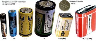
Do you know how to distinguish a communication cable (low-voltage) from an electrical cable (power cable)?
Power electrical cables are divided into high-voltage - more than 6 thousand volts and low-voltage - 220-380 volts. High-voltage ones have a diameter of 40-70 mm, have a core of three, finger-thick, aluminum (rarely copper) conductors and a fairly thick 2 mm screen. Such cables do not give up without a fight, and if it is not disconnected, then damage to such a cable is equivalent to the explosion force of a hand grenade and is also dangerous. Almost always have an armor layer. → → Jokes on the topic
.
Low voltage ones are more varied. Diameter from 20-80 mm. If the cable is not used in circuits of any complex automation, then the core consists of four aluminum (rarely copper) conductors without a screen. As a rule, the sheath of these cables is not smooth and these same cores can be traced by the irregularities. They are also armored. Also, when they are switched on, they do not give up without a fight, but here the strength of the shot depends on the machines through which this cable is switched on. For example, if the cable supplying a multi-story building is damaged, an excavator may completely lose a couple of teeth from the bucket. And don’t let the name low-voltage put you off, because 380 volts of voltage (sometimes sounds like 0.4 kV to electricians) can easily kill a curious person. Electrical cables differ from bonded cables in materials, and although there are exceptions, electrical cables generally have aluminum cores and polyvinyl chloride or paper insulation; bonded cables have copper cores and polyethylene insulation. → → How to distinguish polyethylene from polyvinyl chloride (vinyl)
.
You will not make a high-voltage cable without the necessary knowledge, skills, materials and a high-voltage testing laboratory.
Low-voltage cables are easier to repair, the insulation requirements in them are even lower than in communication cables, but due to the high current, tight contact at the splices is more important (achieved by bolted connections). Due to the danger of electric shock when working on electrical cables, you must be sure that there is no voltage on them, and it will not appear while working on the coupling. In many ways, the restoration of insulation is similar to the repair of a communication cable.
Differences between communication cables
As already noted, they differ in materials of manufacture. In connection, copper is mainly used for conductors and polyethylene for insulation, however, an antique version with a lead sheath and paper insulation is also possible.
Low-current communication cables are noticeably thinner. They have a diameter from 5 to 60 mm, while cables thicker than 40 mm are not currently placed in the ground, but are pulled into the telephone sewer. The number of cores in the cable ranges from 2 to several hundred. The diameter of the cores is from 0.32 mm to 1.2 mm, that is, these cores are noticeably thinner than electric ones
.
In communications, it is customary to distinguish between interstation and subscriber cables. Interstation cables have thicker cores (0.9-1.2 mm) and quadruple twist. Cables for wiring subscriber lines are paired and the cores in them are usually 0.32-0.5 mm. But in reality, a lot is mixed up and the interstation cable that turns out to be unnecessary can be used for individual subscribers. In addition, for laying individual subscribers, PRPPM wire with a copper core diameter of 0.9-1.2 mm was widely used
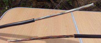
It should be noted separately such a communication cable as fiber optic cable (FOCL). All fiber optic cables have a fairly strong armor coating that is almost impossible to cut through with a simple shovel. Cable thickness from 10 to 20 mm. Modern versions do not contain copper or aluminum conductors. The optical fiber itself resembles horsehair and is multi-colored.
Photo of fiber optic.
There is a separate page about couplings on fiber optic cables, and restoration of optical fibers may not be possible even in a small regional center. Therefore, there is nothing further about fiber optics on this page. However, the sheath on a cable of this type is restored in the same way as on TPP.
Does it need to be restored?
Over the years of the existence of wired communications, so much necessary and unnecessary has been placed in the ground. Military units were especially distinguished by the number of waste cables. Rather than repairing a damaged cable, it was easier for the military to lay a new one. So if something is broken, it does not mean that someone needs this cable.
Cable ends that are carefully severed may carry dangerous voltage.
To check the “need” of the connection cable, the presence of voltage is checked on both sides of the break along the core-ground circuit. A handset, tester, or even a simple earphone is suitable for such a test. If, when connecting, the wire is ground (any pin or screwdriver inserted into the ground is suitable for “ground”), a distinct click is heard in the earphone or handset, or the tester shows a DC voltage of 12 - 60 Volts, then the cable was in use and something was broken. that's what you need.
It is useful to know about communication technologies.
About electrical tape
. Insulating tape is completely unsuitable for sealing a cable located in the ground. Water penetrates between its layers even if its layers are coated with some household glue. Can only be used to seal cables that are constantly exposed to air.
About bitumen
. Usually, people who have observed the work of cable workers suggest covering or filling a damaged cable with bitumen. Believe me, cable operators do not use bitumen in their couplings, but bitumen mastic. The difference between them is plasticity at low temperatures. With the arrival of winter, microcracks form in a coupling filled with bitumen, water penetrates into the joints and causes the insulation to fall. Perhaps mastic used for waterproofing pipes or rubber-bitumen mastic can also be used, but not pure bitumen.
About scratches
. Often people who are not involved in cable work underestimate small cuts in the cable sheath. They believe that if the veins are intact, then everything can be buried out of sight. Alas, a scratch on the PRPPM wire laid in the ground renders the line completely inoperative. Water soaks into the connected TPP cable like into a hose and over time disables it not only at the point of the cut, but also for several meters in both directions.
About paper insulated cables
. These have not been produced for a long time, but they work in some places. The insulation of the cores is characterized by the ability to become damp in the air, so scratches must be repaired immediately (you can use bitumen mastic). More serious injuries can only be treated by specialists. In detail: “Splicing of current-carrying conductors and restoration of their insulation” and “Restoration of lead sheaths.”
Nature of cable damage
When a cable is damaged, it is often not completely crossed, but to some extent only the sheath is scratched. For a communication cable this can be fatal. The severity of a polyethylene cable cut is assessed by whether foil, strands or other insulation layer is visible in the cut.
If only the foil is visible, the shell will need to be sealed (duct tape will not help). And you cannot bury a cable with a damaged sheath in the ground. Almost all connected cables are afraid of water flowing into the sheath. Sometimes a cable with a damaged sheath can work for quite a long time, but problems with it will definitely arise, and do not rely on the fact that the soil in the damaged area will still get dry water there over time (perhaps not relevant for Kazakhstan).
If the cable cores are also visible, you will have to make sure that they are not broken. To do this, a small section of the shell is carefully opened with a knife and the veins are examined for integrity.
If more than three cores are broken, then first study the page about the TPP cable and evaluate the possibility of reliable and correct connection of the broken wires. It may be easier to cut the cable and splice it with a connection, but you can’t do it without the help of professionals. Not all solders can assemble a 10 x 2 TPP cable without errors based on the colors of the cores, although this is possible. Please note that you will have to make two couplings, and, accordingly, you need to insert the same cable.
Drawing a conclusion, it can be noted that in artisanal conditions on multi-pair cables it is possible to restore the sheath and a small number of pairs. On cables with a small number of pairs (KSPP, PRPPM, P270), inserts and full-fledged couplings can be made if the appropriate materials are available.
Repairing a damaged communication cable at home
Repair of minor cuts (scratches)
To repair the shell, you will need bitumen mastic and polyethylene tape 3-5 cm wide (you can cut a plastic bag), and rags. It is advisable to have a blowtorch or gas burner if you do not want to heat the mastic on a home gas stove or fire.
Carefully heat up the bitumen mastic. Heating should be done in a metal container, evenly throughout the entire volume, stirring if possible.
Heated mastic has a temperature above 100°C and any moisture can cause boiling.
While the mastic is heating up, the cable must be cleaned of dirt and wiped dry 15-20 cm in each direction from the cut. At this stage, it is useful to make sure that there are no other scratches on the cable in the excavation area that need to be repaired.
Next, using a dry wooden or metal stick, mastic heated to a liquid state is applied to the cable, trying to cover the sheath over the entire area 10-15 cm on both sides of the scratch.
While the applied mastic has not cooled down, it is tightly wrapped with polyethylene tape. The mastic should be squeezed out along the edges of the tape and smoothed evenly over the surface of the cable.
Just in case, mastic is also applied on top of the plastic film.
The method is not suitable for cables that are at least partially exposed to air. Due to heating in the sun, the mastic will flow out from under the tape.
Other methods for repairing minor cable damage
Welding
. It is produced with special polyethylene tape and fiberglass tape and only on cables with a round profile. Requires special skills and experience. Performed with a blowtorch or gas gun. More details on the page “Restoration of polyethylene casings”.
Heat shrink
. The XAGA heat-shrinkable sleeve can be used not only as a whole, but also in parts. Typically a strip about 15 cm wide is used with a lock of the same width. The shell near the scratch is treated with sandpaper. Set with a blowtorch or gas gun.
There are adhesive heat-shrinkable tubes, but you can't put a tube on a whole cable, and therefore they are almost never used for repairing scratches.
Repairing damage with cable insertion and dead-end couplings.
For a person little familiar with cable technology, it is possible to make a coupling on a cable that has 2-4 cores in the core (PRPPM, KSPP). Theoretically, the technology for sealing dead-end couplings on a TPP cable differs little from the technology described below, but even experienced solders make mistakes when splicing pairs. Therefore, before taking on a cable with a large number of pairs, it is advisable to study the material on the “CCI” page.
Necessary materials
. Bitumen mastic, a piece of cable similar to the one being spliced, a polyethylene tube with a diameter sufficient for free entry of two spliced cables; for cables with more than two cores, thin polyethylene tubes with a diameter of 5-6 mm (cambrics), polyvinyl chloride tape, a blowtorch or other heating device are required mastics.
Correct splicing of cores
. For a regular telephone, the polarity of the connection does not matter, that is, it does not matter which wire of the pair is connected to which. But there is a difference for paired phones (blockers). Therefore, if this anachronism is still used in your area, you will have to figure out which wire to splice where. Signalmen determine this using the “poke” method, that is, they connect and check whether it works or not and whether the number is the same for the desired subscriber. Usually, if the wires are swapped, the phone numbers also change places, but there are also more complex connection schemes. It is possible that the wires of a pair can be distinguished by a break in the cable, be careful. In most cases, incorrect activation of blockers can be corrected later at the cable termination device.
The wires are twisted core to core in such a way that the entire splice can be freely immersed in a dead-end coupling. Insulating tubes are put on twisted cables of four or more cores. In any case, there should be no short-circuiting of pairs or breaks. There is a lot about this on the page “Features of installing rural communication cables.” It is advisable to wrap the cambric sleeves with vinyl or insulating tape. A small picture for clarity.
1 2 3
Repair of communication cables using inserts and dead-end couplings
We heat up the bitumen mastic and at the same time prepare the coupling bodies. In your case, they are made from a piece of polyethylene pipe with a diameter of 16 to 30 mm and a length of about 30 cm. One end of the pipe section is heated on the flame of a blowtorch or gas stove until the edge melts and ignites. At the same time, they try to ensure that the flame warms up the inner surface well. The molten edge is then compressed using a flat surface and the sole of the boots. It turns out to be a glass flattened on one side. This glass is the body of the dead-end coupling.
The resulting glasses are stuck vertically into the ground and almost completely filled with bitumen mastic. When pouring bitumen mastic, its temperature is of great importance. The cable cores, splice sleeves, and the body itself are made of polyethylene, which disintegrates at a temperature of 80 degrees, and bitumen mastic can be heated to a much higher temperature. Before pouring the coupling, its temperature must be checked by immersing the core sleeve in molten mastic. If the sleeve does not lose its shape, then the mastic is not hot and can be poured into the coupling.
Next, the spliced ends of the cable are immersed in a glass filled with mastic. This is done with a smooth movement until it stops and without going back, otherwise the insulating sleeves may slide right into the mastic. Everything is carefully laid out, checked and buried.
Dead-end couplings page
Common mistakes when installing couplings
Contaminated surfaces
The installation of a connecting element on a cable is often carried out in trenches or pits, where it is quite difficult to monitor the cleanliness of the working space. However, when working with couplings, additional protective agents in the form of films should be used. It is necessary to monitor the cleanliness of both tools and consumables, as well as remove contamination in a timely manner.
Violation of connector installation technology
The dimensions of connecting tubes and wires must comply with the requirements of the manufacturer. Otherwise, some defects may appear over time. They must be detected in advance and rubbed with a file, after which the area must be treated with a grinding wheel. Protruding elements of fasteners also need to be sanded. After completing this work, the resulting sawdust should be carefully removed.
Uneven thickness of cuff insulation
This problem can arise when shrinking a sleeve with thick walls using the heat shrink method. To avoid this, it is necessary to evenly heat the entire area to be treated. In some cases this is not possible due to working conditions.
The use of a bent tin reflector makes it possible to evenly distribute heat over the entire surface to ensure uniform heating of the adhesive composition present in the sealant and its uniform distribution.
Installed coupling
Broken coupling tightness
Parts that are installed on high-voltage power lines have three sealed zones:
- interfacial belt;
- internal (in the body);
- on the outer surface of the connection.
To shrink the external sealing belts, additional sealing agents are used to process the joints. After heat treatment, the adhesive composition should protrude beyond the edges of the joint and create a kind of barrier to prevent the ingress of harmful substances.
If the substance does not come out, it means that an error was made during this process. Also, before starting work on laying the assembled compound in the soil, it is necessary to carry out a thorough inspection to detect possible defects. If you find damage to the insulating layer, you need to install a repair sleeve with an adhesive base.
Air masses in couplings
Each cavity between the coupling elements must be filled with sealing material. If an air mass forms in the coupling body, the process of ion formation will undoubtedly begin.
To summarize, connecting elements for power lines must be installed according to strict guidelines and in compliance with certain rules. All actions must be carried out by specialists, since these operations require high qualifications and a decent amount of experience. It is not recommended to do this yourself.
Return to content
3.3. Sealing of couplings at the junction of cables in dissimilar sheaths TPPepZ, TPppZP and TG
3.3.1. According to section 11 of the “Guidelines for the construction of linear structures of local communication networks” (M. SSKTB. 1995), splicing of cables with a polyethylene sheath of the TP type and with a lead sheath of the TG type is carried out using a lead coupling and a lead bushing.
After soldering the lead coupling to the bushing, LG-2 tape is wound onto the bushing, up to half of it, onto the cable sheath for a length of 50-60 mm with 50% overlap. Three layers of PVC tape are wound on top of the LG-2 tape with 50% overlap (Fig. 3.29).
Rice. 3.29. Winding of the junction of the lead bushing with the polyethylene sheath of the cable.
On top of the PVC tape, close to the lead bushing, apply two layers of “Armoplast” with a 50% overlap. Winding starts from the lead coupling and returns to it. On the cable sheath, the tape should overlap the PVC tape. Figure 3.30 shows the application of Armoplast tape at the junction of the lead bushing with the polyethylene sheath of the cable.
Rice. 3.30. Applying Armoplast tape to the joint of the lead bushing with the polyethylene sheath of the cable.
3.3.2. At the junction of cables such as TP and TPV; TG and TPV
Currently, this option is found, as a rule, when installing branch couplings in ATS shafts (station couplings). In this case, sealing is carried out only with LG-2 and PVC tapes. Armoplast tape is not used