A television antenna is a device designed to receive a signal to transmitting equipment. And, depending on what device is used and a certain number and quality of channels are received. Now, in most cases, satellite dishes are used. They are equipped with a certain set of equipment: dish, cable, converter, receiver, and so on.
How to check the performance and technical potential of a television antenna?
But, like any other equipment, this device can fail not only due to mechanical damage, but also if connected incorrectly. In such situations, you need to know how to check a television antenna without resorting to the services of specialists.
There are a number of reasons why a satellite dish on a TV does not work:
- Absence of a power circuit in the receiver-converter flow (both scales are zero, which means there is no contact).
- The antenna is not tuned (there is a signal strength scale, but no quality scale).
- The converter is faulty (the signal strength may be present, but there is no quality scale).
- The memory in the receiver settings has disappeared (during a long “rest”).
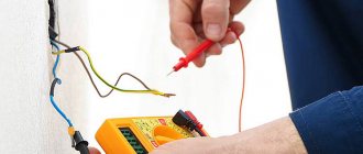
How to check an antenna with a tester (multimeter)
First of all, you should pay attention to the TV cable. It should be intact and without any crimps.
- If this is a multi-story building, then you will only have to check the functionality of one end of the cable (with a plug). For this, a multimeter (tester) is used to measure the resistance between the braid and the central core of the wire. A value of several tens of ohms is considered a normal value. If it is greater than or close to “0”, a break or short circuit has occurred. In this case, it is better to find out whether the neighbors have a signal and, if so, then the problem is in the junction box or in the area from it to the plug.
- If this is a private home, then you can check the resistance of both ends of the TV cable. First you need to unplug all equipment from the outlet. Then disconnect the wire from the antenna and from the TV. And in the same way, use a tester to check the braiding and the central core for short circuits. Here, the serviceability of the cable is indicated by an infinite resistance value. But, if you short-circuit the central core and braid, the multimeter should show a value close to “0”.
When the device detects a malfunction, it is necessary, first, to find the weak point of the cable. This usually occurs in places where there are sharp bends, connected sections, or where the wind sways. If everything is fine with the TV cable, the cause of the problem should be looked for elsewhere.
Power supply device
In the vast majority of cases, the power supply for a television antenna consists of a step-down transformer with a bridge rectifier, a filter capacitor and an integrated voltage regulator.
Power supply diagram
The output voltage of the transformer is about 12-18 V, preferably closer to the maximum value. Why this is so will be discussed below. An integrated circuit of type 7812 is used as a stabilizer. It has become very widespread due to its successful parameters and is available with different permissible power. In the power supply under consideration, you can use a microcircuit with minimal power (a more powerful one is quite acceptable, the criterion here is its dimensions). The domestic analogue of 7805 is K142EN8B (short name - KR EN8B). For normal operation of the circuit, it is necessary that the voltage at its input exceeds the output by at least two volts, and since after rectification and smoothing with a capacitor, the alternating voltage increases by about 1.4 times, the minimum voltage at the transformer output is about 10 V. The above limit is 12 V was selected taking into account a possible decrease in the network voltage.
The capacitance of the filter capacitor must ensure smoothing of voltage ripples. In this case, 220 uF is quite enough. The operating voltage of the capacitor should be several times higher than the rectified voltage, so it is better to take a capacitor rated at 35 V or higher. The LED serves to indicate the operation of the unit.
Very often, an antenna can receive both signals from a distant television center and from a nearby one. In this case, it is possible that the antenna amplifier begins to self-excite, that is, generate its own oscillations. Broadband antennas, which also include the Delta antenna, have a similar disadvantage. The quality of reception is greatly deteriorated. To get out of this situation, reduce the gain of the amplifier. This can be done by reducing the supply voltage. This option is shown in the figure below.
Adjustable power supply
It can be seen that a variable resistor is included in the common terminal circuit (2) of the microcircuit. At the same time, the microcircuit itself is of a different type - 7805 (domestic analogue - K142EN5). At the minimum value of the resistor resistance, the stabilization voltage is equal to the passport value of the microcircuit - 5 V. By increasing the bias at the common pin, you can adjust the output voltage up to the input value.
High-quality adjustable antenna power supplies contain a stabilizer built using an adjustable integral stabilizer type LM317 (analogue - K142EN12). This variety is common, although the simplified scheme has proven itself well and has a lower cost.
Sometimes you can find an adjustable power supply in which a resistor is simply connected to the output conductor. This solution does not stand up to criticism and is typical only for cheap Chinese devices.
How to check the head (converter) of a satellite dish
The most common problem with satellite devices is the failure of the antenna head (LNB) or DISEQC (switch). This is usually understandable if some TV channels suddenly stop showing. The converter can fail due to precipitation, short circuit and sudden voltage surges.
To check whether this problem is actually due to a converter or disk failure, you must:
- Turn on a channel that has stopped working.
- Unscrew the LNB head from the cable.
- Disconnect the center wire from the receiver and connect to the LNB.
- If in this situation the channel begins to show, then the disk (switch) is faulty. Otherwise the converter is broken.
But, if there is no connection even when replacing the LNB head, then you should look for the reason in the equipment settings.
How to check the TV antenna signal
This is a very common error in satellite systems. The equipment seemed to be working normally, but at one point, when you turn on the TV, a window appears on the screen with the words “No signal”.
To check the satellite signal level, go to the receiver settings:
- Open “Menu” - “Settings” - “Password” - “0000” - “Manual search”.
- 2 scales should appear: signal strength and signal quality.
- If both are shown in color and percentage, the broadcast is temporarily unavailable or your subscription has been discontinued.
- A value of zero for both options means there is a problem.
- You should restart the device (turn it off for 1-2 minutes and turn it on again).
- If nothing has changed, take the plate with your hands and turn it, looking for the satellite, horizontally. The plate should be moved at intervals of 1–2 degrees (loosening the fasteners if necessary) with breaks of 3–5 seconds to process the digital signal. For this procedure, you need an assistant who will monitor changes in the signal scale on the TV.
- If everything remains unchanged, you should catch the signal vertically. To do this, the plate needs to be bent up and down, according to the same principle as horizontally.
- When a signal appears in one plane or another, loosen the fastening screws and adjust the antenna.
How to check your satellite dish receiver
Before you begin your next attempt to test the antenna, it is best to try the previous steps again. Perhaps there was a mistake made somewhere. If nothing helps, you can check the receiver for serviceability.
- First, you should go into manual settings and write down the parameters for the satellite of this provider.
- Then, take the device and connect it to another satellite TV.
- After that, select manual search in the menu, where to find the desired satellite and set the already recorded parameters.
- If both scales are colored and have a numerical value, then the receiver is working properly, otherwise it will have to be sent in for repair.
In any case, you should not immediately rush out and buy a faulty element or call a repairman. It is better to try to go through each point of checking the television antenna 2-3 times. And only then can we draw any conclusions.
Setting up television antennas at home is usually done using receiving and reproducing household equipment located in an apartment or house. The presence of a receiver and a TV in this case is sufficient to determine the signal level and correct it. We are, of course, talking about a primitive coordination of the elements of the chain, which includes an antenna, cable and television receiving equipment. For deeper settings, specialists use professional measuring instruments, which can greatly reduce the time of such work and simplify their implementation. The use of such devices makes it possible to determine the signal level in a matter of minutes and adjust the receiving antenna in accordance with the passport parameters of the receiving household appliance.
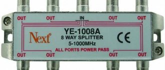
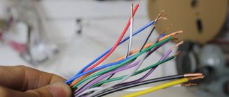
Design and diagram of the crab
The TV crab is a metal box with F-connectors. Inside, on the central terminals of the connectors, parts (high-frequency transformers) of the television signal splitter are soldered. A high-frequency transformer is shaped like a ring or tube made of ferrite with a magnetic permeability of 600-2000, on which 1 to 10 turns of enameled wire with a diameter of 0.2-0.3 mm are wound, evenly spaced around the entire circumference.
In the photograph of the crab from which the back cover has been removed, you can clearly see how the ferrite transformers are wired for connecting three TVs. This crab is assembled according to the Electrical Circuit Diagram below.
All produced crabs are assembled according to the given electrical circuit diagram; there may be minor deviations - additional separating and filtering capacitors, chokes, and matching resistors are installed.
When making an adapter for supplying power to an isolated antenna amplifier, I decided not to install an additional connector for connecting the power supply, but to use one of the connectors for connecting the F-plug. To do this, we had to remove one of the transformers, limiting the crab's ability to connect only two TVs.
As a result of the modification, only two TVs can be connected to the crab, and its circuitry has changed.
All that remains is to install the LC filter in the crab and the adapter will be ready for use. Since the crab body is made of duralumin, the capacitor lead had to be connected to it through an additionally installed brass terminal, screwed to the adapter body using a screw and nut with a shaped washer.
As a result of the modification, the electrical circuit diagram of the crab acquired the following form. As can be seen from the diagram, transformer T1 remained original, but a choke and two capacitors were added.
To better match the circuit, you can solder a 150 Ohm resistor between the output pins XW2 and XW3. You can install the adapter in any convenient place, directly next to one of the TVs, or, for example, at the cable entrance to the apartment. If you need to connect only one TV, then transformer T1 can be removed, and the right terminal of capacitor C1 can be soldered directly to the central terminal of one of the connectors XW2 or XW3, to which the cable going to the TV can be connected.
Checking the TV signal without a TV
The technique for measuring the level of a television signal without using household appliances consists of connecting the appropriate equipment to the circuit between the antenna and the receiver, or directly to the antenna cable. Using this method, the measuring device records the level of the input signal, and the specialist determines its parameters. In accordance with the results obtained, the built-in receiving unit of the TV or a separately connected receiver is configured. In this case, the specialist can only correctly orient the receiving antenna and coordinate its parameters with the passport characteristics of the receiving equipment. Usually the antenna is directed in such a way as to obtain the maximum level of the TV signal.
Modern devices for tuning standard and satellite antennas are now available in a very wide range. These include:
- TV signal level meters with dial or digital indication;
- devices with a built-in compass that determines the position of the satellite;
- devices with their own software and the ability to enter additional settings;
- spectrum analyzers used for finer and more precise tuning of receiving equipment;
- universal analyzers operating in TV receiver mode with support for various image formats.
The choice of the type of measuring equipment directly depends on the type of antenna and the tasks assigned to the specialist.
Other ways to connect the power supply
Using a power supply, you can solve the problem of how to connect the antenna cable to cable television through the wire already included in the apartment. Typically a crab is used for branching. But quite often, with a weak initial signal, the use of crab leads to the fact that the image quality drops significantly, or the TV begins to pick up fewer channels than before.
Circuit of a simple antenna amplifier for 2 TVs
This problem can be solved if you connect not just via cable, but using a signal amplifier and power supply. Using this circuit, you can connect a power supply and make the television signal reception more stable.
TV signal level according to GOST
The TV signal level is measured in decibels (dB), taken in relation to the effective voltage (1 µV). The designation looks like this: “dBµV”. In accordance with existing GOST, the value of this parameter should be in the range from 60 to 78 dBµV (these indicators are focused on a package that includes more than twenty programs). The optimal level of a television signal, at which the input signal-to-noise ratio has acceptable values (26 dB), is an indicator of the sensitivity of the television receiver. This parameter is specified in the device passport. Modern TV receivers are designed for a minimum input signal:
- 32 dBmV in the meter range;
- 37 dBmV in the UHF range.
Taking into account the fact that acceptable image quality is observed only at a signal level value that exceeds the receiver sensitivity rating by 20 dB, this value at the input of the receiving equipment should vary in the range of 52-57 dBmV.
In addition to this indicator, the signal characteristics are seriously influenced by such parameters as the ratio of signal to noise levels, as well as the level of intermodulation (nonlinear) distortion. Typically, such complex measurements are not carried out by specialists, but, nevertheless, the quality of the image largely depends on them.
According to existing standards (GOST [2.3]), the value of these parameters should not exceed:
- -72 dB/mW (70 µV) for meter range;
- -69 dB/mW (100 µV) for the UHF range.
The sensitivity of an individual video channel, taking into account the limitations associated with synchronization, directly depends on the minimum signal amplitude at the input of the television receiver, which ensures stable image synchronization. The meaning of these parameters is as follows:
- in the meter range it is acceptable within -75 dB/mW (40 µV);
- in decimeter - should not exceed -72 dB/mW (70 µV).
Power supply parameters
DIY laboratory power supply
The antenna amplifier requires a power supply with the following parameters:
- constant supply voltage from 9 to 12 volts;
- current value is not more than 100 mA.
As a result, the power of a TV power supply is a few watts, so it can have very small dimensions.
Amplifier power supply with adapter
Measuring a TV signal using a multimeter
A multimeter is a universal measuring device that can be used to measure voltage, current, resistance, capacitance, inductance, and also carry out cable testing. Some types of stationary devices of this type are equipped with a frequency measurement unit. I would like to immediately note that it is impossible to measure the level of a TV signal with a conventional multimeter. If the device has a built-in frequency meter, it becomes possible, when setting up a specific channel, to check the correspondence of the specified value and the actual indicator of this parameter when setting up the antenna. Basically, a multimeter is used to measure the resistance of an antenna cable and check its integrity.
Amplifier purpose
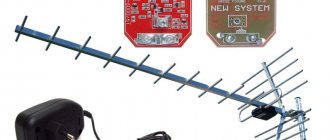
Reliable reception of programs for viewing channels on terrestrial television using a conventional antenna is only possible at a short distance from the transmitting center. In all other cases, the active antenna is supplemented with a reception amplifier. As an example, we can cite Polish antennas, which have become very widespread, and Delta-type antennas.
Polish antenna
Antenna Delta
The main function of TV antenna amplifier:
- increasing the level of the useful signal to acceptable values;
- reduction of interference level.
These qualities are listed because the quality of reception is affected not only by the magnitude of the useful signal, but also by its relationship to the level of interference. Based on this consideration, the antenna amplifier is located in close proximity to the antenna, often entering directly into its structure.
The power supply voltage for the antenna amplifier is supplied through the antenna cable. To isolate the useful signal, an antenna, either Delta or any other, is connected to the TV via an adapter. Some TV or tuner models have an antenna socket that already contains voltage. Thus, the need for a power supply and adapter is eliminated, although this does not exclude the possibility of using them. To do this, there must be an item in the TV settings menu that allows you to turn off the antenna power through the antenna input.
Important! The simultaneous supply of power from the antenna socket and the external power supply is not allowed, as this may lead to failure of one or more devices. At best, the quality of reception will suffer.
Measuring TV signal in SCTV
To measure the basic characteristics of a television signal in a cable TV network (cable television network system or SCS cable network system), you will need a signal generator, a spectrum analyzer and a digital oscilloscope.
These measurements include:
- Impulse noise level. It is carried out by the method of accumulating sweeps, from the characteristics of which, using special software, such characteristics of the output signal as the width and amplitude of the pulses, as well as their periodicity, are calculated. Such measurements are carried out in conjunction with recording the level of total interference. The scan should be recorded at intervals of 2-8 seconds;
- Total interference level. Such measurements are performed using a spectrum analyzer by recording spectral analysis data of the interference, and are carried out at intervals of 8-10 seconds. Testing is carried out over eight hours. In this case, the bandwidth of the device is set:
- at intermediate frequency at 30 kHz;
- via video at 10 kHz;
- the detector is switched to peak mode.
Using the appropriate software, the spectral power is adjusted and the ratio of the signal power level and the total interference for a single channel is determined;
- Determination of the frequency response of the path. The determination of these characteristics is based on the method of analyzing the distortions of a test signal of a certain shape, supplied by a pulse generator to the input of the path. To perform such measurements, the following equipment is required:
- Pulse generator used as a source of the tested signal;
- digital high-frequency oscilloscope (with a bandwidth of up to 50 MHz), equipped with an interface for transmitting received information;
- a device for storing the obtained results connected to an oscilloscope.
The resistance at the input and output of the devices used must correspond to the indicator - 75 Ohms.
How to supply power to the antenna from the TV
First of all, there must be a TV that supports antenna amplifier power. Many modern TVs are already equipped with a built-in tuner and the antenna amplifier can be powered via a coaxial cable from the TV.
Please note that not all TV models support the function of supplying power to an active antenna.
How to connect the power supply to the antenna
There are several schemes for supplying power to the antenna. We suggest you choose one of the following sets of equipment in the desired combination:
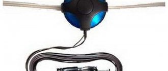
- power injector (1) and 220 V power supply (2);
- 220 V power supply with built-in power injector (3);
- power injector (1) and USB power cord (4);
- power injector (1) and car power adapter (5).
Will an active antenna work without power?
This is exactly the question that customers often ask us when choosing an antenna. Yes, of course, the antenna will work even without power supply, but the efficiency in this case is significantly lower. The antenna will not be able to come close to its declared characteristics, which will only be available when the supply voltage is applied.
The vast majority of antennas for receiving television programs include a signal amplifier. Like any electronic device, it requires a power supply. The main feature is the use of an antenna cable to simultaneously transmit the useful signal and supply voltage. This principle of organizing power supply for an antenna amplifier has long been accepted as a de facto standard by most manufacturers of antennas and amplifiers for them. This is due to the fact that the distance from the amplifier to the power source is large, but no additional cable to the power supply is required.
Antenna with amplifier
Measuring a TV signal in an optical cable
The main element of fiber optic networks is the fiber located inside the optical cable. To maintain and test such systems, specialized measuring equipment is required. Here are some devices without which it is impossible to perform any measurements on optical lines:
- optical reflectometer (OTDR) – makes it possible to determine not only the level of losses in the system, but also the location of damage to the optical cable;
- optical tester - presented in the form of an independent radiation source and a device for measuring optical signal power;
- optical power meter – records the signal level indicator and displays its numerical value on its screen in Watts or dBm. The main measuring element of the device is a photodetector.
- flaw detector – causes a red glow on damaged sections of the optical cable;
- active fiber identifier – the device is designed for a quick, gentle (non-destructive cable integrity) method for determining the presence of a signal and its direction in an optical fiber. It makes it possible to detect the presence of a signal without turning off the transmitting and receiving equipment, as well as determine its strength and direction.
Let's figure out what characteristics of fiber-optic communications we are talking about when servicing and repairing them. The first indicator that experts pay attention to is the level of attenuation of the optical signal at a certain wavelength (measured in dB). This value characterizes the quality of the fiber optic cable and the level of installation work performed during its installation. The main elements of the system that cause this process to occur are:
- optical fiber (losses are measured in dB per unit distance);
- welding connections;
- connectors;
- connectors;
- dividers, etc.
The next important characteristic for optical communications is back reflection. This value determines the power of the signal reflected to its source and is also expressed in dB. The main reasons for the occurrence of a reflected signal, as a rule, are mechanical damage to the optical cable (cracks), the presence of mechanical connectors, or a cable break at the connection point (free end).
The use of the above devices allows a specialist to achieve the output signal to the required level and ensure reliable operation of the receiving equipment located in the apartment or house. So, if you have problems with the image in SCTV conditions, you should contact the operator who provides these services to you.
A television antenna is a device designed to receive a signal to transmitting equipment. And, depending on what device is used and a certain number and quality of channels are received. Now, in most cases, satellite dishes are used. They are equipped with a certain set of equipment: dish, cable, converter, receiver, and so on.
How to check the performance and technical potential of a television antenna?
But, like any other equipment, this device can fail not only due to mechanical damage, but also if connected incorrectly. In such situations, you need to know how to check a television antenna without resorting to the services of specialists.
There are a number of reasons why a satellite dish on a TV does not work:
- Absence of a power circuit in the receiver-converter flow (both scales are zero, which means there is no contact).
- The antenna is not tuned (there is a signal strength scale, but no quality scale).
- The converter is faulty (the signal strength may be present, but there is no quality scale).
- The memory in the receiver settings has disappeared (during a long “rest”).
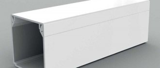
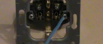
Connection
The industrial adapter for connecting to a TV is connected to the power supply with a two-core wire and has two terminals for connecting the antenna cable. To connect the cable, you need to cut it correctly. The cable that will be connected to the antenna consists of a central core, enclosed in plastic insulation, and a shield braid, which, in turn, is enclosed in insulation.
How to make a power supply from energy-saving lamps
In order to connect the cable to the adapter, you must first carefully trim the outer insulation with a sharp knife at a distance of 2 cm from the edge, being careful not to trim the shielding conductors. Next, the insulation is pulled off the cable. Stepping back 15 mm from the edge, cut off the screen. The central wire with insulation remains. Now, stepping back 1 mm from the screen, very carefully trim the central insulation to a depth of several millimeters. By bending the cable several times at the cut site, you need to ensure that the insulation bursts in a circle. Now it needs to be removed from the core.
Important! You cannot cut the insulation to its full depth, since the central core will break at the point of the cut.
How to check an antenna with a tester (multimeter)
First of all, you should pay attention to the TV cable. It should be intact and without any crimps.
- If this is a multi-story building, then you will only have to check the functionality of one end of the cable (with a plug). For this, a multimeter (tester) is used to measure the resistance between the braid and the central core of the wire. A value of several tens of ohms is considered a normal value. If it is greater than or close to “0”, a break or short circuit has occurred. In this case, it is better to find out whether the neighbors have a signal and, if so, then the problem is in the junction box or in the area from it to the plug.
- If this is a private home, then you can check the resistance of both ends of the TV cable. First you need to unplug all equipment from the outlet. Then disconnect the wire from the antenna and from the TV. And in the same way, use a tester to check the braiding and the central core for short circuits. Here, the serviceability of the cable is indicated by an infinite resistance value. But, if you short-circuit the central core and braid, the multimeter should show a value close to “0”.
When the device detects a malfunction, it is necessary, first, to find the weak point of the cable. This usually occurs in places where there are sharp bends, connected sections, or where the wind sways. If everything is fine with the TV cable, the cause of the problem should be looked for elsewhere.
How to check the head (converter) of a satellite dish
The most common problem with satellite devices is the failure of the antenna head (LNB) or DISEQC (switch). This is usually understandable if some TV channels suddenly stop showing. The converter can fail due to precipitation, short circuit and sudden voltage surges.
To check whether this problem is actually due to a converter or disk failure, you must:
- Turn on a channel that has stopped working.
- Unscrew the LNB head from the cable.
- Disconnect the center wire from the receiver and connect to the LNB.
- If in this situation the channel begins to show, then the disk (switch) is faulty. Otherwise the converter is broken.
But, if there is no connection even when replacing the LNB head, then you should look for the reason in the equipment settings.
How to check the TV antenna signal
This is a very common error in satellite systems. The equipment seemed to be working normally, but at one point, when you turn on the TV, a window appears on the screen with the words “No signal”.
To check the satellite signal level, go to the receiver settings:
- Open “Menu” - “Settings” - “Password” - “0000” - “Manual search”.
- 2 scales should appear: signal strength and signal quality.
- If both are shown in color and percentage, the broadcast is temporarily unavailable or your subscription has been discontinued.
- A value of zero for both options means there is a problem.
- You should restart the device (turn it off for 1-2 minutes and turn it on again).
- If nothing has changed, take the plate with your hands and turn it, looking for the satellite, horizontally. The plate should be moved at intervals of 1–2 degrees (loosening the fasteners if necessary) with breaks of 3–5 seconds to process the digital signal. For this procedure, you need an assistant who will monitor changes in the signal scale on the TV.
- If everything remains unchanged, you should catch the signal vertically. To do this, the plate needs to be bent up and down, according to the same principle as horizontally.
- When a signal appears in one plane or another, loosen the fastening screws and adjust the antenna.
How to check your satellite dish receiver
Before you begin your next attempt to test the antenna, it is best to try the previous steps again. Perhaps there was a mistake made somewhere. If nothing helps, you can check the receiver for serviceability.
- First, you should go into manual settings and write down the parameters for the satellite of this provider.
- Then, take the device and connect it to another satellite TV.
- After that, select manual search in the menu, where to find the desired satellite and set the already recorded parameters.
- If both scales are colored and have a numerical value, then the receiver is working properly, otherwise it will have to be sent in for repair.
In any case, you should not immediately rush out and buy a faulty element or call a repairman. It is better to try to go through each point of checking the television antenna 2-3 times. And only then can we draw any conclusions.
Connecting the power supply to the adapter
Since I decided to connect the power supply to the crab through one of its F-connectors, to implement this idea I had to make an adapter from an ordinary double wire coming from the power supply to a coaxial cable.
To do this, you need to take a piece of antenna cable 5 cm long, cut one end of it and put on an F-wrap. To the second end, as shown in the photographs, solder the wires coming from the power supply with a shift. The positive terminal is soldered to the central core of the antenna cable.
If you don’t want to mess around, you can install a standard connector in the crab body for connecting power supplies and through it supply voltage to the antenna amplifier through a home-made adapter.
February 20, 2018
The article covers the following topics:
A television antenna with an amplifier, also called an active TV antenna, is widely used to receive a television signal at a long distance from a repeater. This is their main advantage, since it is possible to receive a digital terrestrial television signal on an antenna without an amplifier only at a short distance from the repeater - usually up to 20 km. Or an antenna with a large intrinsic gain, which is achieved due to the significant dimensions of the antenna. In this case, it should be mounted outdoors and, if possible, as high as possible.
The use of antennas with an amplifier often raises the question of how to supply power to an active antenna, or more precisely to its amplifier. Most modern active antennas require a supply voltage of 5 V. In our article we will look at various circuits for powering an antenna amplifier over a coaxial cable:
- from the receiver or TV;
- from the power injector;
- from the power supply.