When a light switch fails, it becomes necessary to disassemble it. If it is discovered that the device does not work, the first step is to determine whether there is voltage in the apartment network. Then you need to remove the light bulb connected to the switch and check the serviceability of it and the socket. It often happens that the fault turns out to be somewhere else. If there is electricity in the rooms and the light bulb and socket are in order, the cause of the malfunction most likely lies in the switch itself.
How to disassemble a light switch yourself
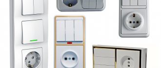
Before removing the switch, you need to determine its type. It could be as follows:
- One-, two- or three-key.
- Passage. In fact, it is a contact switch and is similar to a switch only in appearance.
- Dimmer – a switch with a built-in device for regulating the brightness of incandescent and halogen lamps. It can be mechanical or with a microcontroller.
- Pulse - a button connected by contacts to a special relay;
- Touch – acoustic (triggered by a loud sound), controlled from an IR remote control or radio remote control.
Most users use key switches, which are worth considering first.
Power outage
Before removing an outlet or light switch, first turn off the electricity. In the room, the electrical wiring branches into several lines: sockets, lighting and leads to the electric stove. At the switchboard, the lighting power is turned off automatically, and then the absence of voltage is checked at its output.
Sometimes it turns out that it is not the phase wire that is connected to the machine, but the neutral wire. This can be done by an unqualified electrician who assembled the panel circuit. The circuit will work, but the lighting wiring will be constantly energized, regardless of whether the circuit breaker is turned on or not. If such an error is found, it should be eliminated by making the necessary changes to the circuit.
If you have difficulty choosing a line, you can turn off the input machine, turning off the power to the entire apartment.
Where to start
If the light does not light up when you press a key, the switch is not always the cause of the breakdown; you should not immediately start disassembling it. First, it doesn’t hurt to check the presence of voltage in the network, as well as the condition of the incandescent lamp. If there is no voltage, the switch is most likely ok.
You need to find out what is wrong with the network (short circuit, power outage, damage to the power cable, etc.) and fix this problem. With a burnt out light bulb it’s even easier - you need to replace it. If the network and the lamp are in order, it’s time to take a closer look at the switch.
First you need to find on the distribution panel the circuit breaker through which this particular switch is connected, and move the levers to the “down” position, i.e. turn it off. After this, you should use a tester to check the presence/absence of voltage at the output.
The procedure is simple and does not take much time; you should not neglect it, even if you are completely sure that the device is definitely disconnected from the power supply.
You can make an assumption about the nature of the breakdown even before the repair begins. A common problem is oxidation of contacts inside the device. If the switch does not work only sometimes, most likely the reason is bad contacts, which will simply have to be cleaned.
In addition to the “shell” of oxidation, carbon deposits can also accumulate on the metal switch plate. It can also be cleaned of accumulations to restore the operation of the device.
Serious damage can be caused by improper installation of the switch. Due to inexperience, some amateur craftsmen connect not a phase to the machine, but a zero wire. As a result, the switch seems to work, but all lighting wiring connected in this way remains energized.
It happens that simply replacing a burnt-out light bulb in such a network can result in an electric shock. It is enough to correct the circuit for everything to work correctly.
Before disassembling the switch, you need to de-energize either a separate line through which power is supplied to the device, or the entire apartment
Such installation errors can lead to the fact that after the machine is turned off, the line will still remain energized. This is one of the reasons why you should always check even when the device is turned off.
If there is voltage, you need to turn off the power to the apartment or house. If sparks appear inside the switch every time you turn it on and off, this usually indicates that the contacts of the device are of poor quality.
In some cases, it is necessary to replace the entire switch with the same one, just a new one. Usually, for replacement, they select exactly the same model that matches both the socket box and the interior.
If for some reason you need to install another model, you should make sure that the existing opening is suitable for it. Otherwise, you will have to re-install a new socket box.
The reason for frequent voltage drops in the network can be not only the general condition of the electrical network, but also a large number of powerful electrical appliances that are connected at the same time. On this matter, you can consult with an experienced electrician; you may need to make adjustments to the existing circuit.
How to disassemble a switch
Disassembly tools will require a flathead and Phillips screwdriver. Most models use flat mounting screws, but sometimes you can find cross-shaped ones.
Switches come with one, two or three keys. Without removing them, the device cannot be disassembled, since the fastening elements are hidden inside.
The devices vary in design, and disassembly methods may vary:
- The key is pressed against the wall with your thumb on one edge and is removed if you pull the other one towards you (Fig. a). You should not pick it with a screwdriver or knife, as scratches will remain on the surface. Some keys fit tightly and can be pryed off by the edge with a screwdriver.
- The key is pressed on the sides with your fingers, the fastenings are recessed, and it moves freely.
- If there are connectors on the sides, pry them up with a screwdriver and gently pull them towards you, after which the key comes off.
Removing the keys (a) and frame (b) from the switch with your own hands
Double and triple keys are removed in turn. Then you need to remove the decorative frame, which is pressed against the mechanism by an insert located in the middle and held by latches. It should be removed by prying the edge with a screwdriver (Fig. b).
Afterwards, the fastening elements for the wiring and the switch mechanism will become accessible.
Switch mechanism with wire fastening elements
The frame may be secured with screws that need to be unscrewed. Most often it is fixed on the side latches. The plastic fasteners bend one by one and the frame comes off.
Before dismantling the mechanism, you need to find the core through which the phase is connected to the switch. To do this, voltage is applied to it, and the indicator checks the presence of voltage on both contacts. Then the key switches to the next position and the test is repeated.
If in all cases voltage remains on one contact, it means that the supply phase conductor is connected to it. The other core will go to the lamp. The phase for two- and three-key switches is found similarly. The home handyman should not be concerned about the number of wires connected. Among them there will be only one wire through which the supply voltage is supplied. The power supply is then switched off again and operation continues.
The fastening screws hold the spacer tabs that rest against the side walls of the mounting box. If you loosen the screws, the mechanism will freely come out of the wall. If it is secured to the box with screws, they should be removed.
Then unscrew the screws securing the wires and remove it from the wall recess. Check the absence of voltage on the mechanism using an indicator screwdriver. The input conductors can be secured with self-clamping terminals. To easily pull the wires out of the connector, press the locking levers. First, the phase wire is disconnected and insulated. Subsequently, it is reconnected to the phase contact of the new or repaired switch. If the pins are marked "L" and "1", the connection is made to "L". When they are designated “1” and “2”, the phase is connected to contact “1”.
Designation of contact L of the supply phase
In two- and three-key switches, the contacts are designated in a similar way:
- two-key – “L”, “1”, “2” or “1”, “2”, “3”;
- three-key – “L”, “1”, “2”, “3” or “1”, “2”, “3”, “4”.
In all cases, the devices have one common contact with the connected supply phase and outlet contacts to the lamps.
The phase connection must be to a fixed contact, and the outlet wire to a moving one. If everything is done correctly, the key will be pressed from above in the “on” position and from below in the “off” position.
After disassembly, the switch in a particular case looks as shown in the figure below (LEZARD brand). It contains 3 main elements: mechanism, frame and key.
What does a disassembled switch look like?
Recommendations for repairs
Problems with contacts are easily resolved. They need to be inspected first. If there is a layer of oxidized metal on them, you should remove it and then install the contacts in place.
If the contacts are not just oxidized, but have pronounced traces of melting, they usually cannot be repaired and the device will have to be completely replaced. Removing carbon deposits from the contacts is very simple; you can use a knife or the end of a flat-head screwdriver to do this.
A visual inspection of the wires both in the electrical outlet and in the junction box will help identify and eliminate the cause of the breakdown. It is necessary to restore damaged elements or replace them completely
When working with wires, you need to pay attention not only to the condition of the bare ends, but also to the quality of the wires themselves. For example, fragile wires can easily break, break, etc. In this case, part of the wiring will have to be replaced.
Among the common causes of weakening and disruption of contacts are:
- increased humidity, which stimulates oxidative processes;
- incorrect, for example, too loose fastening of wires;
- excessive load, as evidenced by sparking, buzzing, crackling and other similar signs;
- network voltage exceeding the permissible level;
- frequent voltage drops, etc.
To reduce problems with carbon deposits on switch contacts, experts recommend using energy-saving lamps rather than traditional incandescent lamps. The load on the network is reduced, and components wear out more slowly.
Switch connection. Video
The video talks about how to properly connect a single switch to the network.
The method of disassembling a switch depends on its design. You should remove the keys and decorative frame carefully, since the fastenings are mostly made using plastic latches of different designs. Work on disassembling the switch should be carried out with the mains voltage turned off.
The switch is considered the main device that helps control lighting. Today the following types are common: single, double and triple. The last type is designed for connecting several lamps, that is, for combined lighting.
General view of a three-key switch with a socket
Features of analysis of different types of switches
There are several switch designs on the market, and their removal may vary slightly. It’s better to immediately learn the nuances of working with non-standard mechanisms:
- Three-key. They are used in rooms where there are many spotlights or several different types of lighting. Each of the buttons is responsible either for turning on a specific device or for its own section. The keys themselves are quite thin; they need to be removed one by one. There is usually a small hole at the bottom that can be pryed with a screwdriver to remove it.
- Dimmer. This type of switch is adjusted by a rotary mechanism. The removal principle is the same, only the rotary control is removed instead of a button.
- Sensory. To disassemble this technological version of the switch, you need to dismantle the outer panel. Usually a special tool for this is included in the kit. If it is not there, you can use a flat-head screwdriver, but you need to do this very carefully, because the glass of the panel may be damaged.
When removing panels from touch devices, the main thing is not to damage them. - Twin design. The double version, where in addition to the switch there is also a socket, will have to be completely disassembled. You need to start with the socket, because the fastening bolt is usually located on it.
- Walkthroughs. There is little difference in design, except for the number of wires inside the box.
You can disassemble a light switch with an installed indicator in the same way. An additional advantage of the indication design is that without a special screwdriver you can find out whether there is voltage.
Applications, Benefits and Methods of Use
A three-key switch with a socket, despite its ease of operation, is rarely installed. The connection diagram for a three-key switch with a socket is more complicated than a regular one, because there are three contacts going to the lighting device at once. This unit has many functions and takes up minimal space, since three devices are located in one housing.
Three-key switch connection diagram
The socket is a separate device. Although it is located in one building, it works independently. “Zero” from the distribution box goes to it, and “phase” is connected from the switch jumper.
Among the advantages of such a three-key switch are:
- saving electricity;
- compactness;
- the ability to control lighting in various rooms;
- easy regulation and switching of the light source (if dimmers are not used);
- possibility of combining lighting.
The use of a three-key switch is necessary for:
- changes in lighting intensity;
- control several lamps simultaneously.
If the device is equipped with a block with a socket, then it is considered the most functional.
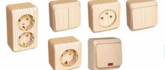
Types of devices
The model range of blocks is varied, it is always possible to find a product that matches the interior of the room. Such devices may differ in functionality.
According to this criterion they are divided into:
- Regular. Some of them have an indication, it indicates the location or the switched on key, they work in the dark;
- Walkthroughs. They are installed in a long corridor, on a staircase, etc. They are used to control lamps located in various places.
Note! When choosing, you must visually inspect the product. It should not have burrs, abrasions or damage. You should hear a click when switching keys.
The device has self-clamping lemmas. They are necessary for fixing and connecting wires. When the cores are pulled out (which is strictly prohibited), the special latches-clamps fail.
Connection features
There are many models of a three-key switch with a socket, but its connection remains the same. The unit should be connected in the same way as a single or double model. The power cable is connected to the input of the device itself, and the wires run from the contact of the block with the switch to the light bulbs. Their number must match the device keys.
Basically, the socket is equipped with a separate neutral wire and, according to the diagram, is not connected to the switch, but they have a common “phase”. All “zeros” from the lamps and the socket itself are connected to the junction box. The “phase” is connected to a common contact included in the switch. The lighting wires are placed on separate blocks. It is from them that the voltage is transmitted to the light bulbs. At the ends of the cores, approximately 10 mm of insulation is removed. Since the contacts are tightened with clamps, and the wire can break, such devices will prevent this from happening.
NShVI - special lugs are used for connections
Basically, the switch block is mounted on the wall, in a special niche. For these purposes, calipers or spacer legs are used, and a decorated frame is put on top.
Usually a switch with keys and a socket is installed near the door of the room. The block helps to change the lighting and connect various household appliances used in the bathroom or toilet.
The distribution box has 5 connections. The ground wire should always go to the outlet. If the lamp has metal parts, then it is necessary to protect against electric shock. There is a special screw connection for this purpose.
Removing the frame
Removing the switch housing
The next step in disassembling the electrical structure is removing the frames. They can be attached to the base in two ways - clamping or screw.
In the latter case, the frames are secured with miniature screws, which can be unscrewed in a matter of seconds using a Phillips or flat-head screwdriver. In the first case, the frames are secured using special clamps; to dismantle them, you just need to bend them. To speed up the process, first remove one clamp, and then proceed to the second.
Connection methods
There are two main schemes for connecting a three-key switch, and in one, a distribution box is required (for twisting the wires), and in the other, the connection is located in the switch block. Let's consider each scheme separately.
With junction box
How to properly connect a three-key switch with a socket in this case? The basic rules that must be followed are as follows:
- they dismantle the old unit, after which 5 wires stick out from the wall;
- turn off the current;
- straighten all the wiring, supply power;
- using the indicator, find the “phase” (L), which is located on only one core;
- looking for “zero” (N);
- both wires are connected to the socket, with L going to the contact that goes to the switch jumper, and N to the free one;
- the other 3 wires are connected to the remaining contacts;
- When you switch keys, the lights should light up.
The connection diagram for a three-key switch using a junction box looks like this
On a note. Dismantling involves removing the old switch, cleaning the niche and wires, and checking the wiring. Only after this they begin to install the new device.
Before starting work, it is first determined whether N or L breaks in the room using a switch. Basically, this should be a “phase”. If this is not the case, then “L” goes from the junction box to the luminaire. That is why “zero” is supplied from the switches. In this incorrect version, N and L are swapped in the socket with the switch block.
Without junction box
Let's look at how to connect a block with an outlet directly. When dismantling the old unit, 8 wires will appear from the wall. If they are the same color, then proceed as follows:
- de-energize the line;
- carefully straighten the wires and make sure that the bare ends do not touch;
- they find a two-core wire (from it power is supplied to the unit and to the lighting), for this, voltage is applied and the “phase” is determined with an indicator;
- de-energize the line and mark the found wire (you can use electrical tape);
- looking for “zero”;
- 6 two-core wires stick out from the wall, which are necessary for three lamps (kitchen, bathroom, toilet);
- each has its own “phase” and “zero”;
- one core is taken from each of them and connected to N coming from the junction box;
- “zero” is applied to the socket contact from this connection (it does not have a jumper);
- N is connected to the socket and goes to all lamps;
- the found L coming from the shield is connected to the socket (second contact);
- other wires going to the lamps are connected to 3 contacts (switch block).
Important! This scheme has a drawback: twisted “neutral” conductors, which must be hidden in the switch block with the socket.
Installation of conventional three-key switches
General structure and connection principle
Each of us probably has an idea of how a regular switch works. This is an electrical device designed to close or open an electrical circuit, at the household level most often used to control lighting devices in an apartment and house. For this purpose, it is equipped with a special mechanical device that allows you to quickly switch the working contact to the on or open position. Speed is very important - the less time required for such a short circuit (opening) - the less likely the formation of an electric arc, which can quickly render the device unusable. This speed is achieved using flat or round springs, rocker arms with balls, and other instantaneous response options. Modern switches with touch panels also use electric keys.
How does a regular light switch work and how is it installed?
Probably every self-respecting home owner should know this - you won’t call a repairman every time for a trivial reason. How the switch works and how you can install it yourself is described in detail in a separate article on our portal.
A three-key switch differs from a regular single-key switch only in that it has three independent contact switching mechanisms, and this allows you to control three different “channels” for supplying voltage to lighting (or other household) devices. However, most switches of this type have one input L and three separate outputs L1, L2 and L3. As a rule, on the switch body itself the switching diagram of its contacts is very clearly shown.
For example, two three-key switches (on the back) from different manufacturers.
Let's take a look at the illustration above. It shows two different switches, with small, completely unimportant differences. On the left, the common input is organized through contact No. 6, contacts No. 4 and No. 5 are paralleled with it by a common bus. Well, the outputs are separate - through contacts No. 1, No. 2 and No. 3. On the right switch, the input is made through contact No. 5, but otherwise everything is the same.
When installing home wiring, the requirement must be strictly observed - the switch is installed to break the phase, which is why the letter L appears in the name of the contacts. In this case, if it is in the off position, there cannot be dangerous voltage on the electrical appliance (lamp), and you can safely for example, replacing a burnt-out lamp.
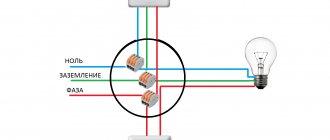
The schematic diagram for connecting a triple switch (for now we are considering it without a socket) will look something like this:
Standard switching diagram for a three-key switch to control three different lighting fixtures
A few clarifications on this diagram. Conductors N and L come from the distribution board. Since the switch does not require a neutral wire to operate, it goes directly to the lighting fixtures. Only phase wire L goes to the switch, which is connected to the common input. Three phase wires come out of the switch, L1, L2 and L3, each of which goes exclusively to its own lighting device S1, S2 and S3.
Expert opinion: Afanasyev E.V.
Chief editor of the Stroyday.ru project. Engineer.
You can make a remark - often three-phase switches are used to control lighting in one room, but again - each of the channels is tied to its own lighting device or group of lamps. For example, L1 works to turn on the central chandelier, L2 turns on the embedded spotlights, and L3 is responsible for the LED lighting hidden in the two-tier ceiling. There can be many options.
There is one more important note. On sale you can find three-key switches with a separate phase at the input. Outwardly, they are practically no different from ordinary ones - you must definitely pay attention to their connection diagram. An example is shown in the illustration below.
This is also a three-key switch, but it has three independent inputs. It will require a little modification to be included in the standard scheme.
Such products allow you to slightly modify the system for switching on devices, for example, to set the dependence of the second switching channel on the first, etc. (the second key will not work if the first one is not enabled). There may be other applications for such devices. But if you plan to adhere to the scheme shown above, then in its “pure form” this type is not suitable. True, “bringing it to mind” if you happen to acquire it through an oversight is as easy as shelling pears. To do this, you just need to make jumpers between the first-second and second-third inputs from pieces of solid copper wire with a cross-section of 1.5 mm². In a word, connect the inputs with a homemade “bus”.
A simple modification in the form of two jumpers
At the output, everything remains unchanged - there is a division into three independent phase conductors, each of which is controlled by its own key.
Installation and connection of a three-key switch
Installation and connection of a three-key switch may be required when reconstructing home wiring or when replacing a previously installed but faulty device. Both cases have their own characteristics.
Installation and connection of a three-button switch when reconstructing home wiring
It will be easier if you don’t explain it manually, but show the main operations step by step in the table, accompanied by illustrations.
So, the table below will show from “a” to “z” the process of organizing lighting in three adjacent rooms with control of lighting devices from one three-key switch. Let’s make a reservation right away: according to the authors of the plot, the action begins with laying cables in the grooves already existing on the walls. Whether in your case the wiring will be placed in corrugated pipes above the suspended ceiling, or whether it is planned to be hidden under a screed - from an electrical point of view, nothing will change, that is, the connection of the device itself, in principle, will not tolerate any variations.
| Illustration | Brief description of the operation being performed. |
| Starting position - the distribution board is visible on the left (naturally, it is located here conventionally - just to make it easier to understand the laying of cable routes). On the wall in the background is the door to the bathroom, next to it (not noticeable in this picture) is the door to the bathroom. It is precisely between them that a three-key switch will be located, “responsible” for controlling the lighting in these two rooms and in the kitchen (it is not yet visible - it will be clear later). For the installation of this unit, grooves have already been cut, the distribution box has been installed in place, and strictly vertically below it is a socket box (mounting box) for the switch itself. | |
| A three-core VVG cable with a monocore cross-section of 1.5 mm² is laid from the distribution board to the distribution box - for lines intended exclusively for lighting, this will be more than enough. Such a cable can be round or flat in cross-section - from an electrical point of view, there is no difference. But for laying in a groove, a flat one, I think, is preferable. | |
| The end of the cable that is inserted into the distribution board is cleared of the outer insulation layer. Underneath there are three wires with color-coded insulation: - The blue wire is the neutral conductor (N), - The yellow-green wire is the protective grounding wire (PE). — The third wire in this case has white insulation - this is the phase conductor (L). The color of the phase wire insulation is sometimes different - black, red, brown, yellow, etc. – but not blue or yellow-green. | |
| The ends of the wires are stripped of insulation to a length of 10÷12 mm using a special tool - a stripper. Then the phase wire is connected and clamped into the terminal of the circuit breaker, the one that is “assigned responsible” for this section of the household electrical equipment. Naturally, the machine itself must be in the off position. | |
| The neutral and protective conductors are connected and clamped each in their own distribution board bus: blue - in the neutral, yellow-green - in the grounding bus. | |
| On the opposite side, the cable is inserted into the junction box. It is usually recommended to leave a margin of approximately 150 mm so that subsequent installation is not accompanied by difficulties due to the short ends of the wires. The outer insulation is removed from the cable, and the ends of the conductors are stripped. It is advisable to mark the wires so as not to get confused later during switching. It happens that color marking is not enough, and it can lead to an error during installation - this will be explained clearly below. For marking, you can use pieces of white electrical tape (or heat-shrink tubing), on which the printed letters or symbols will be clearly visible. In this case, everything is clear with the markings - white is marked L, phase; blue – N, neutral (zero); yellow-green – PE, protective grounding. | |
| The installation box, or, as it is more often called in common parlance, the socket box, is located at a distance of 900 to 1500 mm from the floor surface. There are no hard and fast rules here - how convenient it is for the apartment owners and how it fits in with the overall interior decoration. But the fact that the socket box must be located on a vertical line from the center of the distribution box - this rule must be strictly observed. | |
| A four-core cable of the same conductor cross-section, for example, VVG 4×1.5, is laid from the distribution box to the socket box. | |
| A margin of approximately 120 mm is left, the top insulation is removed, the cable conductors are stripped and marked. This is the very nuance - for which labeling never hurts. The insulation of one of the conductors in this cable may also be blue. Just as you might get caught with a yellow-green conductor. But – the phase is interrupted at the switch, that is, all the wires will be phase wires: one common and three “for distribution” to lighting fixtures in different rooms. And color coding, unless made clearer, as shown in the illustration, can easily be misleading, especially in a junction box. And here it won’t be far from a short circuit and other troubles. So it's worth thinking about... | |
| The upper end of the 4x1.5 cable is similarly cut and marked in the junction box. After this, it is advisable to immediately begin distributing conductors into groups for further switching. | |
| Let's return to the installation box (socket box) - it is quite possible to connect and install the three-key switch itself. It's not difficult at all. | |
| Conductor L, that is, the phase supply, is connected to the contact of the same name on the switch, on the side where it has only one terminal. (As an option, on some switch models this terminal is also designated “L in” or “L input”). But even so, it is very difficult to confuse. | |
| Conductors L1, L2 and L3 are connected to the switch terminals located on the opposite side. These terminals may also have labels, so it is difficult to get confused on this issue. After connecting the conductors, we can say that in this node, on the switch itself, the electrical installation work has already been completed. The switch itself is inserted into the socket of the socket box and fixed there with expanding claws and (or) screws, if the design of the mounting box allows for this. | |
| The laying of cables to the lighting fixtures begins. Let's start with the first one - the three-core VVG 3x1.5 cable is inserted into the distribution box and goes into the groove... | |
| ...and then, through the cavity of the floor slab, it “emerges” in the center of the bathroom ceiling. | |
| Here, when installing a lamp, the cable is passed through the body of the ceiling lighting fixture with a margin of 100÷120 mm... | |
| ...then it is cut, the conductors are marked. Marking, in fact, is not particularly needed here, but this is a matter of the “culture” of the master. The phase wire is called L1 here. | |
| The wires are connected to the terminals of the lighting device. The principle is simple: - The blue conductor is connected in a terminal to the blue conductor of the lamp. — For the yellow-green protective wire in devices with a metal body, a special screw or terminal connection is provided, indicated by a grounding symbol. — The remaining phase wire is connected to the remaining socket on the terminal - the color of the phase conductor in the lamp can be anything, you can’t guess (except blue and yellow-green). | |
| In the distribution box, the cable laid to the first room is cut and marked. The conductors are distributed into groups - approximately as shown in the illustration. | |
| The second cable is laid - to the next room (for example, to the bathroom). Everything is done exactly the same... | |
| ...only the marking of the phase conductor connected to the lamp in the bathroom is already L2. | |
| And here - the same cable is cut, marked and the conductors are distributed among the switching groups. | |
| Finally, a cable to the lighting fixture in the third room - the kitchen. | |
| The cable is routed through a hole in the ceiling, divided into sections, and marked. The phase conductor is marked here as L3. | |
| Just for more variety, the examples show the connection of this cable to a pendant lamp. The difference, however, is small... | |
| It happens that in such lamps there are simply three wires coming out, there is no terminal. It's okay, such a connecting block is easy to buy in a store. Or use slightly more expensive, but much more convenient WAGO lever terminals. | |
| First, the wires coming out of the lamp are clamped into the terminal... | |
| ... and then, based on the color marking and in compliance with the same principle that was explained in the story about the first lighting device, the conductors of the laid cable are connected. | |
| But the last cable is inserted into the junction box, the conductors are stripped and distributed into groups. | |
| Let's look at the groups a little more specifically - highlight them in the figure with boundaries and repeat the purpose of the conductors: 1 - two wires are connected L - a phase from the distribution board and then - to a three-key switch. 2 – four neutral wires N: one comes from the neutral bus of the distribution board, and the rest disperse through the lighting fixtures. 3 – four PE protective conductors: one from the grounding bus of the distribution board, and three diverge through the lighting fixtures. 4 – phase conductor L1 coming from the switch is connected to the same conductor going to the first lighting fixture. 5 and 6 - by analogy with 4, phase wires L2 and L3 from the switch are switched with phase conductors of the second and third lamps. Everything is ready for switching. | |
| To connect wires, you can use various technologies - from twisting using special caps to soldering. But the optimal, most convenient and reliable option seems to be the use of branded terminal blocks from WAGO. Especially - in this design, with levers that make it very easy to carry out both switching and dismantling of the connection, if the need arises. I know that such terminal blocks are often criticized and their reliability is doubted. For ley lines, perhaps there is a rational grain in these doubts. But for lighting circuits, you can completely trust them. | |
| Here's what the distribution box might look like after making connections with WAGO terminal blocks - everything is very neat and clear. | |
| There may be nuances. For example, a home network does not have a ground loop. Then the yellow-green PE protective conductors are excluded from the general “ensemble”, the laying from the shield to the distribution box and from it to the lighting devices is carried out with two-core cables. And the box itself becomes more spacious. But when it comes to connecting the three-key switch, everything remains unchanged. | |
| And on lighting devices, the ground terminal in this case is ignored and remains empty. However, many lamps with a plastic body do not have such a grounding connector at all. | |
| So, the electrical installation work has been completed, all the necessary sections of wiring have been laid... | |
| ...and you can move on to finishing, during which the cable grooves will be closed. | |
| The distribution box is closed with an inconspicuous lid. The three-key switch is finally fixed in its socket socket. | |
| Then a decorative frame is installed on the switch, and, in sequence, all three keys. Now you can screw the lamps into the lamp sockets, turn on the machine in the panel and test the operation of both the switch and the lamps. |
Naturally, the work process was shown with some simplifications and conventions. For example, regarding the sequence of finishing operations and installation of lighting fixtures, it is usually done the other way around. But this is only for ease of understanding of the circuit diagram of a section of home wiring tied to a three-key switch, responsible for lighting in three adjacent rooms.
Installing a new three-key switch to replace the old one
Another problem is that the three-key switch that had previously served faithfully failed. You need to install a new one with the same “functionality”.
The task seems to be much simpler - there is no need to lay cables. This is true, but there may be surprises here too. They mainly concern the correct determination of which wire should go where and what to connect to.
As required by all safety requirements, before dismantling the old switch, you should turn off the circuit breaker in the panel responsible for lighting, thereby temporarily de-energizing the work area. If one is not allocated, you will have to turn off the power to the entire apartment using a common circuit breaker.
When removing the old switch, it will be useful to immediately remember (take a photo with your smartphone) the location of the wires. If the owners were happy with it, then it was best to keep it that way. This would seem to be easy to do if the wires have different insulation colors or have some kind of markings on them. Then the entire process of replacing the switch will be limited to checking the condition of the conductors, possibly updating the stripped ends to “fresh”, not pinched and non-oxidized areas (if the length of the protruding wires allows). Well, then you can install the switch in the same way as shown above.
What to do if the wires in the socket or switch are short?
An unpleasant situation - you remove the old switch or socket, but you cannot install new devices - the length of the wires is no longer enough for this. There is a way out - a separate article on our portal describes in detail how to build up wires in an outlet .
But quite often we come across cases where old aluminum wiring is used in a completely impersonal white shell, and even pretty tattered and burnt. And if the plans do not yet include replacing the wiring with normal copper wiring, then nothing can be done; you will have to test the old one - which of the wires is responsible for what.
Agree that understanding this intricacy of wires in impersonal identical insulation is not so easy.
With the power turned off, it is necessary to process the ends of the wires, removing worn areas, clean them, and then move them apart to prevent them from accidentally shorting. After this, the machine is turned on, but making sure that there are no strangers (especially children!) in the area near the exposed wires.
Ideally, you can use an indicator screwdriver and a multimeter for testing.
An indicator screwdriver allows you to find the phase wire - when you touch it, the LED lights up. On the remaining wires, if the wiring and lighting fixtures are installed correctly, nothing should glow.
An example of searching for a phase wire using an indicator screwdriver.
If the incoming phase is detected, and the remaining wires are “silent”, all that remains is to figure out which one goes to which lighting device. To do this, it is better to turn off the machine again, just in case, and start dialing.
This can be done quickly and accurately with a special device for checking wiring - a digital cable tester. With it everything works without the need to use any additional wires.
A special cable tester is a digital device that allows you to quickly understand the intricacies of hidden wiring.
It is clear that not everyone has such a device. Therefore, you can get by with a regular multimeter, putting it in the circuit testing mode. True, you will have to use a long piece of wire to reach the lighting fixtures at all three points. After ringing, the conductors should be marked - and then you can proceed to the usual installation of a three-key switch, as shown above.
There is another way, although not entirely “safe” from a security point of view. If the input phase conductor is guaranteed to be identified, then you can connect to it through the same WAGO terminal a small piece of insulated wire with a short stripped end (it will be enough to strip literally 2 ÷ 3 mm from the edge). With this improvised “probe” they successively touch the exposed wires going to the lighting fixtures and track where the light turns on. Well, then everything is simple.
But there are situations that are more complicated. So, for example, none of the wires show phases. This means that, with a high degree of probability, a mistake was once made, and a neutral conductor was connected to the breaker. And the phase is constantly on all three lighting fixtures. In this case, it is still recommended to invite an electrician to make changes to the switching in the junction box and restore the correct position.
It also happens that one wire does not show anything, but the phase on the other three is on. This is a variant of the previous case, the phase is simply transferred through the spiral of incandescent light bulbs. If you unscrew the bulbs, this phenomenon will disappear. Otherwise, everything is the same as described in the last paragraph.
Another option, the most “mysterious” one, cannot be ruled out: the indicator shows the phase in general on all four wires, but meanwhile, before the switch was removed (failure), the light control worked normally. This phenomenon is more typical for old houses with “ancient” aluminum wiring, where the induced currents “walk as they please”, and this can only be combated by a major conversion of the entire network to copper cables.
How, in this case, can you decide on the “pinout” of the conductors if you don’t have a special device?
Again, not a completely safe, but effective method - using a self-made probe.
To make such a “device” you will need a piece of two-core insulated cable, a light bulb socket (no matter E14 or E27) and a 220-volt incandescent light bulb itself with an appropriate base and the minimum possible power, for example, 15 or 25 W, and a WAGO two-pin terminal block. Everything is assembled approximately as shown in the illustration below:
Homemade “tester” for checking the “pinout” of wires for a three-key switch.
- So, all wires “glow” when touched with an indicator screwdriver. How to test?
- When the machine is turned off, the wires are spread as far apart as possible to avoid a short circuit.
- Light bulbs in lighting fixtures must be screwed into place and are guaranteed to be in good working order.
- From the total number of wires, one test is selected. It is connected to an improvised tester via the WAGO terminal. After this, the power supply is turned on.
- Next, you need to act very carefully so as not to touch the bare ends with your hand. Use the second wire of the tester (its bare tip) to touch the remaining stripped wires in turn and observe the result. There are three possible options:
- The light on the tester does not react at all.
- The lamp on the tester lights up, the lighting devices are “silent”.
- Both the lamp on the tester and the lamp in one of the rooms light up.
A. If the tester is installed on one of the outgoing phases, then when it touches other conductors it will only work once. At the same time, the lamps on both the tester and the lighting fixture of this line will light up. So, by the way, it is possible to quickly find the phase wire - it is when you touch it that it will trigger. And the direction of the outgoing phase also becomes completely clear.
B. To check - the incoming phase is guaranteed to be on that wire, when testing which the device lamp will light up in all possible cases, when touching any other conductor. At the same time, the light will come on in one of the rooms (except for touching the neutral conductor, which is discussed below).
- Looking ahead somewhat, it can be noted that the above cases No. 1 and No. 2 are typical only for a switch with a socket. The fact is that then in the overall “bouquet” there is also a neutral wire.
- The first option is possible when the neutral wire is connected to the outgoing phase - nothing will happen, since the same zero is located on the lamp socket, no current will flow, not a single lamp will light up.
- The second option is when connecting the incoming phase and zero. The tester light will not allow a short circuit to occur, and will simply show that current has flowed through it. But the rest of the lighting devices will not work.
- By sequentially performing several such checks (when moving the device to another conductor, do not forget to turn off the machine), you can quickly and accurately understand the “real picture” and mark the wires.
Well, you already know what to do next.
Installation errors
Many people wonder how to connect a three-key switch with a socket so that the work is done efficiently and everything functions correctly. Often, when connecting the socket unit with the switch, something goes wrong, and as a result, the chandelier does not light up.
Let's look at the errors that may occur when connecting devices:
- The socket works, but the switch does not. If you confuse “phase” and “zero”, then this will happen. That is, L is connected to the common line of the switch with a jumper instead of N. To correct the situation, you need to check everything with an indicator and redo it;
- When installing unit connections or replacing an old one, check the voltage in the wires. Often, electricians install separate wiring for the device, and there are two power supplies at the same time. Therefore, by assembling a sample according to the circuit, a short circuit is often created;
- Two keys do not work until the third is pressed. This means that the “phase” was connected incorrectly. Instead of the general input, it is connected to the output of the third key. To correct the indicator, you need to check the voltage of the contacts. If it lights up in all cases, it means that the switch breaks the “zero”, that is, someone crossed the wires in the panel. To correct this, unscrew the light bulbs and check the “phase” conductors. They find “zero” (common) and transfer it to the central contact of the three-key switch;
- Electricians do not recommend leaving the socket device in the block connected through one key, although this is convenient, since when pressed the light disappears. This is explained by the fact that various household appliances are often connected to the outlet, for example, a hair dryer from 1.5 to 2 kW. Extensions or tees can also be connected here. The device contacts are not designed for this voltage. In the best case, the unit will turn off and stop working, in the worst case, a fire will occur.
Three-key switch: convenience and energy saving
A three-key switch allows you to save up to a third of electricity. The device is a fairly simple device, externally differing from one- and two-key models only in the number of keys. Unlike simple switches, the three-key model has three groups of contacts for phase and zero. The main thing is not to confuse them when connecting.
Preparatory work includes:
- mandatory network de-energization;
- wire distribution (zero, phase);
- phase search (using an indicator screwdriver).
If the old switch has failed or repairs have been made to the room, it becomes necessary to connect a new switch. Before you begin installation, you need to buy the switch itself.
Selecting and purchasing a three-key switch
It is recommended to purchase equipment only from well-known companies. This guarantees long-term operation of the product and its trouble-free service.
When purchasing, it is recommended to pay attention to the following details:
the keys should turn on with a characteristic click and not stick; the surface of the switch must be smooth and even; on the back there should be a diagram for connecting to the electrical network; It is important to check the degree of protection and make sure that the product can be connected in a specific room.
The degree of protection is designated as IP and consists of two numbers (from zero to six). The first number is responsible for dust protection, and the second for water protection. The higher the number, the more reliable the protection. For living rooms, a switch with an IP rating of 20 is suitable. If the room has high humidity (bathroom, bathhouse) or an increased amount of dust (attic), then the IP rating should be at least 44. Electrical installation work outdoors requires the installation of a switch with IP 65.
Connection diagram
Domestic and foreign companies are engaged in the production of electrical equipment, but the connection diagram for a three-key switch is always the same.
The general diagram will help you correctly connect any three-key switch
A set of necessary tools
To connect you will need tools, most of which are found in every house or apartment:
- nippers and pliers;
- Phillips and flat-head screwdrivers (depending on the features of the product);
- indicator screwdriver;
- insulating tape;
- screwdriver;
- knife or stripper (a tool for convenient removal of insulation).
Manufacturers
Basically, the consumer makes a choice in favor of an aesthetic model; it all depends on the interior design of the apartment. If the design is “antique”, then the choice should be made on models from Fede.
The Gira triple switch with socket has an elegant design and is in great demand. Legrand models are perfect for any interior, as they have horizontal and vertical designs.
ABB supplies the market with a large range of switch units with LED socket outlets. They add functionality to aesthetics.
The Russian one produces combined models. You can find a single block made of plastic with vertical installation. Models with triple switches and a socket are available: without a grounding contact, with red backlight or with a Euro socket with protective curtains.
Important! All switches have a voltage of 220 V, and the rated load ranges from 10 to 16 A.
The buyer decides which manufacturer of switch to choose.
This is how you install a three-key switch with a socket yourself. If you have no experience in this matter, it is better to contact a specialist. He will not only do everything quickly, but will also help you choose the best devices, advise where to install them, and check all the electrical equipment in the apartment.
Typical mistakes at work
The most common mistakes are using excessive force when removing keys and frames. This leads to deformation and scratches and damage to the integrity of the part. In this case, you need to purchase new switches, since the components for them are not sold separately.
The most dangerous mistake is neglecting the rules of personal safety, which poses a direct threat not only to human health, but also to human life. Before carrying out work, it is important to turn off the power supply in the room at the panel.
Video
The three-key light switch is designed to control three lighting circuits. Moreover, each circuit can have any number of light bulbs - one, two, three or more.
The connection must begin by connecting the wires to the switch in the installation box. And to do this, you first need to disassemble it.
Connecting wires to the switch
Remove the keys from the switch. You need to start from the central one. There is usually a gap underneath it. Insert the tip of a screwdriver into it and, with a little force, snap off the key.
The rest can be removed by hand without using a screwdriver.
Next, on the sides, again using a screwdriver, pry up the latches and release the decorative trim.
The central part of the switch with 4 contacts should remain. One on top and three on bottom.
The top contact may not always be centered, keep this in mind.
This single terminal must receive the common phase power conductor from the distribution box.
The bottom three are connected to the wires going to the light bulbs, that is, to separate circuits No. 1, No. 2, No. 3.
To connect you will need a 4-core cable VVGnG-Ls 4*1.5mm2. From the junction box in the groove, lower it into the socket box where the switch should be mounted. Then you start connecting the wires.
Connect the phase conductor to the common central terminal.
Connect the remaining three wires to the outgoing circuits to the lower terminals. In order not to get confused in the future, it is better to label them.
Insert the switch into the mounting box and secure it there. Place the keys in reverse order, starting with the outermost ones. You simply snap them back into place.
In doing so, pay attention to the location of the keys.
The correct position is when the lighting turns on when the key is pressed up, and turns off when the key is pressed down.
Now you need to correctly connect all the wires in the junction box.
Several cables can come into the junction box.
Firstly, this is a three-wire power cable from the lighting circuit breaker installed in the electrical panel. Secondly, a 4-wire cable goes down to the three-key switch, which you have already connected from below.
Well, then there may be options. If you have one chandelier with 3, 6, 9 bulbs, then you can connect it with one single five or 4-core VVGnG-Ls cable with a cross-section of 1.5 mm2.
If you have three independent lamps, in different parts of the room or house, then you will have to run a separate 3-core cable to each of them. Let's consider the last option in more detail.
Nuances of disassembling switches of popular brands
Design features exist not only in different types of switches, but also among products from different manufacturers. Main nuances that need to be taken into account.
- Makel . The switch frame is fixed with special elastic elements that go deep. To get to them, you need to pull the cover towards you. It is also worth considering that the screws are located on the inside, so access to them will only be after removing the mechanism from the socket.
- Legrand. This manufacturer equips its products with retaining petals that are held in the socket box. These fasteners must be loosened before dismantling.
The mechanism of the device is from Legrand. - Wessen . To remove the keys from Wessen devices, you need to grab and press the protruding side and pull it towards you. The fixing elements will come out of the grooves; the buttons can be left aside. Wessen switches feature a continuous cover plate design that is secured with two bolts.
- Lezard . The company's product range includes switches with different frame fixing elements. If these are screws, they need to be unscrewed with a screwdriver, and the side latches are bent with a screwdriver, knife, or other thin object.
Wire connections in the distribution box
So, in the junction box you will have 5 cables. You need to avoid getting confused and correctly connect their wires to each other.
To do this, always start the connection with the neutral and grounding conductors. Regardless of the number of circuits and light bulbs, all zeros must be combined into one common point.
The same applies to grounding conductors. On lamps they are connected to the housing. Although in some cases they may not exist at all.
The fastest way to connect the cores is through Vago terminal clamps. For lighting loads this is a very good option.
Try to choose the colors of the cores in accordance with the current rules. Zeros are blue conductors, groundings are yellow-green.
Pay special attention to the fact that the zero does not go to the switch, but goes directly to the lamps. Only the phase should be broken through the contacts of the three-key switch.
It remains to connect the phase conductors. You need to start with the phase coming through the cable from the input machine.
You connect it only to the common phase conductor going to the central terminal of the three-key switch and nowhere else. This will trigger the phase on the switch.
Next, connect the three wires coming out of the keys with the three phase wires of the outgoing circuits to the lamps. You do this with three different wago clamps.
If you have previously marked the wires, you can easily recognize which key will turn off which light bulb (toilet, bathroom, hallway, etc.)
If assembled correctly, the distribution box should have 6 connection points.
Before directly applying voltage, you must once again check the entire connection diagram of the 3-key switch. If there are no errors, then turn on the automatic lighting and use the keys to start your lamps.
Relieve stress from the workplace
Any work in the apartment related to electricity must begin with de-energizing the work area. If you have a separate circuit breaker for each room, then turn off the one from which the given room where you will remove the switch is powered. If there is one common input machine per apartment, turn it off and take measures so that no one can turn it back on. It will be good if it is located at the entrance to the apartment. But when the machine is located on a common area, it is better to hang a “Do not turn on!” sign. or put someone on duty.
Using an indicator screwdriver, check that there is indeed no voltage at the workplace. How to do it right? First, test the operating condition of the indicator screwdriver in an area known to be live, such as an on-site distribution panel. When it comes into contact with a phase wire, the indicator window lights up, which means the screwdriver is working. Now go back into the room and check that there is no voltage in the junction box by touching the power supply wires. The indicator screwdriver does not light up, which means everything is in order, you have secured the work area and you can safely remove the switch from the wall.
Connecting a 3-key switch and socket
Often, a triple switch is installed in the same block with a socket. How to make this connection correctly?
First of all, you should know that for such installation it is already necessary to use a copper cable with a cross-section of 2.5 mm2.
A cable of this cross-section should go not only from the distribution box to the switch, but most importantly from the switchboard, to this very junction box.
Run the 5*2.5mm2 cable down the groove to the switch+socket block. Now it will be necessary to set not only a phase, but also a zero. It is better to connect the common phase conductor to the contact of the socket, since it is on it that the load is greater than on the lamps.
And then, using a jumper, connect this phase to the upper terminal of the 3-key switch.
Zero is connected to the second contact of the socket. The remaining three wires, according to the previously discussed diagram, are routed under the three lower contacts of the three-key switch.
The wiring in the junction box is carried out almost similarly to that discussed above. Except that it is necessary to connect another neutral wire to the common zero point.
1The most common mistake is that the socket works, but the switch does not.
The point here may be that you simply mixed up the phase and neutral on the outlet. And accordingly, they connected the jumper to the common terminal of the switch not with the phase wire, but with the neutral wire.
Using an indicator screwdriver, double-check where the phase is coming from.
2If you are not installing a socket-switch unit in a new location, but are replacing an existing one, be sure to check the supply voltage on all wires.
Often, some electricians run separate wiring for the outlet and separate wiring for the switch. As a result, you may have two power supplies in the unit at the same time. And by assembling the circuit according to the above instructions, you can inadvertently create a short circuit.
3The light on two keys does not light up until you turn on the third.
As soon as you turn it on, everything works as it should. It's all about incorrect phase connection. You launched it on the output contact of the third key, and not on the general input. Again, everything is decided by checking the indicator.
4 Most often, problems arise when replacing old switch-socket units and old three-key switches with new ones.
You start checking the voltage on the contacts, and the indicator screwdriver shows three incoming phases instead of one! That is, it lights up on all three contacts at the same time. How is this possible?
But the fact is that the switch in this case does not break the phase, but the zero!
The electrician who directly connected the old switch himself a long time ago may not be at fault. It’s just that over time, someone else transferred the wires in the meter or the common switchboard to your apartment.
So it turned out that where there was a phase before, a zero was formed. Often, understanding switchboards is not easy even for the installers themselves.
The indicator lights up on the contacts because the bulbs are screwed into the sockets. As a result, the circuit turns out to be closed through the filament.
Unscrew all the lamps and check the phase conductors again. The glow in the three phases should disappear. For the correct connection, here you already need to find a common zero and throw it onto the central contact of the new three-key switch.
The best way is to find the cause in the switchboard, inviting a professional electrician and restoring the normal power supply circuit.
5Try never to connect a socket in the unit through one of the keys.
Many people find it convenient to press a key and the light in the socket goes out. This is not recommended. This is due to the fact that usually a powerful load is connected through the socket contacts, for example a 1.5-2 kW hair dryer.
But you can still connect a tee or extension cable through it! The switch contacts are not designed for a current of this magnitude and duration. As a result, after some time, the voltage in the entire unit will disappear, unless a fire occurs even earlier.
Sources - Kabel.RF
Dismantling the old block
Almost every day we come across the concept of “Kick-Ass”. Another kicker - at the end of the article.
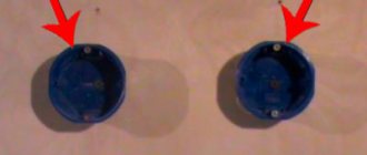
2.Old socket block with switches in disassembled condition
What do we see? Everything is loose and rickety, the two upper switches are in a completely dead state, the third is not connected, and according to the owner, it never worked. The socket is more or less compared to them, considering that in such a place it is almost never used.
The panel house is 40 years old. The lights in the kitchen and bathroom are turned on at least 10 times a day. 40x365x10=146 thousand times. We did a good job.
At this stage, we understand the wires, check where the phase is, and turn off the power. In this case, you must have a headlamp; you can’t do without it.
We take out the insides. The main thing is not to break the wires and notice where everything goes.
3. We take out all the insides - the old socket, switches, metal box
What kind of lighting do you prefer?
Built-in Chandelier
The bad ends that went to the switches had to be cut off - they were still short.
The two bottom wires go to the socket. On the left is zero, on the right is the phase, which in the old days electricians designated with black rag tape (there was no other tape, no markers).
It is worth saying that for some reason the antique metal installation box is attached as tightly as tin. It is fastened with some screws and nuts that must be turned. I have replaced such blocks in prefabricated houses more than once, and each time tearing out this box is torture. I use powerful pliers and a large flathead screwdriver.
4.No one will ever need this again. Thanks for your service!