Preparing the engine for installation
In addition to the fact that it is necessary to prepare the site for mounting the electric motor, it is necessary to carry out certain work to prepare the device itself before starting work. It is important to note here that the electric motor arrives at the site for installation already assembled. If the rules for transportation and storage of this equipment were not violated, then there is no need to disassemble it for inspection. In such cases, you need to proceed with the following steps:
- first you need to conduct a full external examination;
- Next you need to start cleaning the base plates and legs of the frame;
- It is important to check the threads before fastening the device, for which purpose they run the nuts, and also wash the foundation bolts with a solvent to get rid of dirt;
- after these actions, it is necessary to inspect such parts as leads, brush mechanisms, commutators;
- All bearings are checked separately;
- before installing the electric motor, it is necessary to carry out work to measure the gaps between all important parts, for example, between the shaft and seals;
- a separate procedure is checking the air gap, which is located between the moving part of the rotor and stator;
- you need to inspect the entire rotating part of the rotor so that it does not touch any other parts of the machine, and use a megger to make sure that the required winding resistance is present.
To carry out all equipment inspection work, a special stand is allocated, which is located in a separate room. After the inspection and before installing the electric motor, the electrician who carried out the inspection must report the presence or absence of defects to the senior worker.
If no external damage was found during inspection, then another preparatory procedure must be carried out. It is necessary to blow out the unit with compressed air. But before that, you need to check the device itself to ensure that it only supplies dry air. To do this, it will be enough to point it at another object and turn it on. During purging, you need to manually rotate the rotor to make sure that the shaft rotates freely in the bearings. The outside of the engine must be completely wiped with a cloth soaked in kerosene.
Measures before installing the engine
Before installing the motor on an electrical installation, it is necessary to carry out inspection (preventative) work. Otherwise, if any malfunctions are discovered in the future, then all the work was done in vain. When installing the electric motor, you should:
- Clean the electric motor from dust and dirt, carefully inspect the accessible internal parts and check for foreign objects;
- blow out the electric motor with dry compressed air at a pressure not exceeding 2 kg/cm2. When blowing through an open-type electric motor, in order not to damage the winding insulation, you should not use hoses with metal tips. If there is no compressed air, you can use any compressor, even a car compressor;
- Rotate the electric motor rotor manually to ensure that it rotates freely and that there is no jamming or knocking.
Working with bearings
There are many different versions of electric motors according to the installation method, but for all there are some common operations that must be carried out in any case. Flushing sliding bearings refers to this type of work. There are several ways to achieve the desired result.
First you need to remove all remaining oil from the parts, for which you need to unscrew the drain plugs. After this, the plugs are screwed back in, and kerosene is poured in instead of oil. You cannot turn on the device; you must manually rotate the rotor or the armature of the equipment. In this way, you can remove all remaining oil, and then drain the kerosene in the same way as you drained the oil. But this is not the end and you need to do the flushing again, but this time with fresh oil, which is also drained. Only after these two operations have been completed can the bath be filled 1/2 or 1/3 full with fresh oil for work.
It is worth noting that only plain bearings are washed in this way. Rolling bearings, regardless of the installation method of the electric motor, are not washed. The only requirement is that the amount of oil does not exceed 2/3 of the total volume.
Installation of assembled electric motors
Installation of assembled electric motors weighing up to 50 kg on a low foundation is carried out manually. The procedure consists of two stages:
- Connection of the motor to the actuator. This is done either through a belt/gear drive or using couplings. Regardless of the connection method, you must first check with a level the position of the motor in the horizontal plane in perpendicular directions. Experts prefer to use the “gross” level, since its special shape makes it convenient for placement on the shaft. Iron pads are installed under the paws of the unit (wooden pads are deformed during use). The parallelism of the shafts of the rotating mechanism and the engine and the compliance of the width of the pulleys are checked using a metal ruler or a narrow cord.
- Shaft alignment. It is necessary to eliminate lateral and center displacements. Most often, radial-axial clamps are used for alignment. Angular and side clearances are measured with a macrometer, indicator or feeler gauge. If the sum of the values of even and odd measurements is equal or the difference between them is no more than 0.4 mm, the measurements are considered correct.
The foundation bolts are tightened starting from the axis of symmetry of the supporting part and moving evenly towards the edges.
During installation, it is necessary to wash the bearings. To do this, unscrew the drain plugs and remove the remaining oil on the bearings, after which the plugs are screwed in. Kerosene is then poured into the bearings while the rotor or armature is rotated by hand. The kerosene is drained and the bearings are washed with oil to remove any remaining kerosene. Fresh oil is poured into the bearings in a volume of 1/3 to 1/2 of the bath capacity. Rolling bearings do not require changing the lubricant.
Carrying out measuring work before installation
Installation work includes a stage at which it is necessary to check the insulation resistance.
If the electric motor is DC, then the resistance is checked between the armature and the excitation coil; in addition, it is necessary to check the insulation of the armature itself, as well as the brushes and excitation coils in relation to the motor body. Naturally, if the motor itself is connected to the network, then before to start measurements, you need to disconnect all the wires that go from the network and the rheostat to the equipment.
Installation and adjustment of 3-phase electric motors with a squirrel-cage rotor must be accompanied by measuring the insulation resistance of the stator windings in relation to each other, as well as to the housing. However, this procedure can only be done if all 6 ends are brought out. If there are only 3 ends of the windings outside, then you need to check the insulation of the winding in relation to only the housing.
The technology for mounting electric motors with a wound rotor differs in that here insulation measurements must be carried out between the rotor and stator, as well as the insulation of the brushes in relation to the housing.
As for the device for measuring insulation, a megger is used for this. If the power of the device is no more than 1 kW, then the device is taken with a maximum scale of up to 1 kW. If the engine power is higher, then the megger should be rated at 2.5 kW.
Preparatory stages
The foundation should be checked first. To do this, an inspection is carried out:
- concrete condition;
- main axial dimensions;
- elevation marks of supporting surfaces;
- axial dimensions between holes for anchor bolts;
- sizes of niches in the foundation walls;
- hole depths.
Then the electric motor is prepared for installation. It is placed on a shield in a room specially designated for this. The procedure consists of the following operations:
- external inspection of the engine;
- cleaning the feet of frames and foundation slabs;
- washing foundation bolts;
- checking thread properties;
- checking the condition of bearings;
- visual inspection of slip rings, commutators, brush assembly and leads;
- checking the gaps between different components (cover - plain bearing shell, bearing seal - shaft, active part of the stator and rotor steel);
- testing free rotation of the rotor;
- measuring the insulation resistance of windings with a megameter;
- checking for absence of contact between fans and covers;
- inspection of insulated bearings and brush crossbar.
If there is no external damage, the electric motor is purged with compressed air (to check the air supply at the required pressure, the jet is directed onto any surface). If malfunctions are discovered during the inspection, the person in charge (installation manager, foreman or foreman) is notified. At the end of the test, wipe the engine with a rag soaked in kerosene.
Installation of the unit and connection to mechanisms
If everything has become somewhat clearer with the type of electric motor, the installation and preparation of which strongly depend on its purpose and the rotor itself, then next you need to figure out the connection of the device and other mechanisms. It is worth noting that if the weight of the equipment is no more than 50 kg, then it can be installed manually if the concrete platform is not too high.
As for connecting an electrical device and other mechanisms, a coupling or a belt or gear drive is used for this. Any installation version of the electric motor needs to check the position in the horizontal plane using a level, and this must be done in two mutually perpendicular planes. The “gross” level, which has a special recess suitable for the motor shaft, is best suited for this.
Electric motors can be installed either on a concrete floor or on a foundation. In any case, metal pads must be placed under the legs of the frame in order to very accurately adjust the position of the device in the horizontal plane. For example, it is impossible to use wooden supports for this, since when tightening the bolts they are compressed, and when pouring the foundation they can swell, which in any case throws off the position of the machine.
Regarding the repair and installation of an electric motor with a belt drive, it is very important to accurately maintain the parallelism of its shafts, as well as the mechanism connected to them. The same rule applies to the center line, which must coincide across the entire width of the pulleys. If the width of the pulleys is the same, and the distance between the shafts does not exceed 1.5 meters, then all measurements can be carried out using a steel ruler.
To do everything correctly, you need to attach a ruler to the ends of the pulleys and adjust the electric motor until the measuring tool touches the two pulleys at 4 points. It also happens that the distance between the shafts is more than 1.5 meters, and there is no alignment ruler at hand. When repairing and installing an electric motor in this case, you need to use a string and brackets that are temporarily attached to the pulleys. Adjustment occurs until the distance from the bracket to the pulley is the same.
Rice. 39. Alignment diagram on the foundation of the stator plates: 1 - crankshaft; 2 - level; 3 - rod or ruler; 4 - plumb line; 5 - plate; 6 — linings; 7 - foundation)
At the same time as the slabs, anchor bolts are placed in the wells. The axial marks marked on the slabs are combined with the transverse axes according to the marks of the foundation benchmarks. Next, the horizontality of the slabs and their height position are verified using linings (Fig. 39). A wooden strip or ruler with a level is placed on the slabs along the mark of the transverse axis. The position of the transverse axis of the stator is marked on the shaft according to the drawing. At this mark, cords with plumb lines are lowered on both sides of the shaft. To check the position of the slabs relative to the shaft axis, the distances a and from the center lines of the holes of the anchor bolts to the plumb line are measured in several places. The distances a and ay must be equal (permissible deviation ± 1 mm). It should be taken into account that the sum of these distances and the diameter of the shaft must be equal to the distance between the center lines of the anchor bolts according to the drawing. If the audi distances are unequal, the plates are shifted in the required direction.
To align the stator height, the main shaft and the distance from the bottom of the rack to the lower generatrix of the shaft are taken as the base.
The horizontality of the slabs is checked by a level, which is placed on each slab in two mutually perpendicular directions. The permissible slopes of the slabs are 0.1 mm per 1 m along the shaft axis, 0.3 mm per 1 m along the transverse axis of the electric motor. The slopes of both slabs must be in the same direction.
Next, tighten the nuts of the anchor bolts. The tightening rod is checked with a feeler gauge and a hammer (tapping) for the fit of the slabs to the packs of linings, as well as for the level of possible horizontal violations.
Electric motors of opposed compressors. Their installation has some features related to the location of the rotor relative to the compressor crankshaft.
Installation of electric motors, the rotor of which is installed at the end of the crankshaft, cantilevered or supported on an external bearing, or on an attached shaft supported on an external bearing, begins with the installation and alignment of the foundation plates, tightening the foundation bolts.
When installing the rotor on the shaft console, the assembly is performed on the installation site, on a layout of wooden sleepers. The rotor and shaft are inserted into the stator in two steps. The sling is positioned so that when lifting the rotor and shaft take a horizontal position, at the same time it is necessary that the end of the shaft opposite the rotor can be inserted into the stator to its maximum length. During the second slinging, the rotor is completely brought into place. The coil windings are protected from damage by cardboard or ironite gaskets. The shaft and electric motor assembly is placed on frame bearings.
The rotor can be installed on the crankshaft console even if the shaft is placed in frame bearings. To do this, the stator, after preliminary installation and alignment on the plates, is moved as far as possible away from the frame. The rotor, suspended on a sling, is placed on the shaft console using a pressure device, the grips of which are secured to the cheek of the first crank. After aligning the rotor and installing the keys, the stator is returned to its original place using jacks.
When calibrating the gap between the cores of the stator and rotor coils during the final installation of the stator, it is necessary to take into account the deflection of the cantilever end of the shaft under the influence of the mass of the rotor. This should also be taken into account when adjusting the divergence of the cheeks of the crankshaft closest to the rotor by changing the position of the remote bearing. When checking the gaps between the stator and the rotor on the shaft console, one should take into account the one-way force of magnetic attraction that occurs if the gap is uneven, a force that can partially compensate for the weight of the rotor, thereby reducing the gap and the load on the bearings. For opposed compressors, the magnitude of the eccentricity at which a one-sided supporting magnetic force occurs must be at least 0.2 of the gap value for the M10 base and 0.3 for the M16 and M25 bases and directed upward.
The crankshaft is connected to the additional shaft by flanges, which are made integral with the shafts. The connection is made before installing the rotor on the attached shaft according to the factory control marks. The shafts are centered using a projection on one of the flanges and a cavity on the other. When the axes coincide, the bolts connecting the flanges should fit tightly into the holes from light blows with a hammer on the gasket. Often it is necessary to ream holes due to some displacement of their centers, discrepancy between the holes and the diameter of the bolts, or relative displacement of the flanges. The flanges are connected by four mounting bolts of reduced diameter, placing them crosswise around the circumference. A set of three reamers is used, considering that an allowance of up to 0.2 mm is removed in one pass. The diameter of the last ream should be equal to the diameter of the fitting bolt.
A device is also used, including a clamp with a bushing to guide the reaming, which is fixed on the crankshaft in front of the flange, and a thrust stand mounted on studs instead of the main bearing cover adjacent to the frame. A screw is attached to the thrust stand, with the help of which the axial feed of the reamer is carried out. The reamer is rotated manually using a ratchet or regular wrench. The thrust post can also be made in one piece with the clamp and guide sleeve; in this case, the thrust post can be installed on either side of the flange.
After installing the fit bolts, remove the mounting bolts. The holes in which the mounting bolts were installed are deployed. The tightening sequence is criss-cross.
The straightness of the common axis of the crankshaft and the attached shaft is checked by the divergence of the cheeks of the first crank from the flange, for which both shafts, after connection, are placed in pre-fitted shells of the main bearings of the frame and the remote bearing. The divergence of the cheeks in the vertical and horizontal planes is brought to zero by changing the position of the remote bearing. Then, using an indicator, measure the runout of the journal of the attached shaft by turning the shaft one revolution. The indicator is mounted on the stand of the remote bearing. Runout, indicating a break in the shaft axis at the point of their connection, is eliminated by secondary, more accurate tightening of the flanges.
When the attached shaft arrives assembled with the rotor, in addition to the centering operations described above, after installing the remote bearing, the runout of the attached shaft flange is determined by the divergence of the cheeks. During one revolution, the displacement or fracture of the axes of the connected shafts is checked.
Two indicators are installed on a stand attached to one of the main bearing studs: the rod of one of them touches the generatrix, the rod of the other touches the end of the flange of the attached shaft. The defect is eliminated by retightening the bolts of the entire connection. If it is necessary to check the perpendicularity of the flange end to the shaft axis, use one or two indicators, which are mounted on brackets to the bearing cover studs. The shaft is rotated, noting the indica readings every 45° of rotation. The amount of runout, indicating non-perpendicularity, is equal to the difference in the indicator readings (in mm) taken at opposite positions of the crank and divided by the distance between the measurement points (in m). This value should not exceed 0.05 mm per 1 m diameter. Working with one indicator, it is necessary to eliminate the maximum shaft displacement.
Rice. 40. Installation diagram of the electric motor of a two-casing opposed compressor: 1 - compressor frame: 2 - remote bearing; 3 - lower half of the stator; 4 — telescopic stand; 5 - rail; 6 - level; 7 - jack
Non-perpendicularity of the flange is eliminated by processing on the wall, and if it is insignificant, by sawing and scraping.
Electric motors that arrive assembled and are connected to the compressor by a coupling are subjected to shaft alignment, the procedure for which is outlined below.
In large double-casing opposed compressors, the electric motor is located between the casings (Fig. 40). The stator is split from two halves. The rotor shaft weighing 8.5 tons rests on two remote bearings mounted separately on the foundation. The shaft is connected by couplings to the crankshafts of both compressor housings. The stator slabs are installed on the foundation and aligned with a level on pads laid on concrete pads. When transporting the lower half of the stator weighing 12.5 tons by crane, a wooden beam is placed in it along the diameter so that the free ends of the joint do not come together. Two support jacks are installed under the lower part of the stator.
Remote bearings are installed on the foundation on slabs, aligned with the help of pads. The bearing on the commutator side has electrically insulating gaskets. The lower half of the stator is aligned with respect to the remote bearings using strings that are pulled on telescopic stands: one along the axis of the bearings with their mutual misalignment along the parting plane (permissible deviation ±0.1 mm) and the second along the transverse axis of the electric motor. The strings must intersect at right angles, with the axis of the bearings located above the axis of the electric motor by 2 ± 0.5 mm. An indicator of correct installation of the lower part of the stator is the coincidence of the string with the axial marks on the plane of its connector. The height marks of the parting planes of the lower half of the stator, as well as the height marks of the bearings, are checked with a level 6. The bearings should be located 2 ± 0.5 mm above the stator. The height is adjusted using pads placed between the plate and the bearing base.
Permissible differences in height marks for one bearing are 0.0 mm, between bearings are ±0.5 mm, for stator parting planes are ±0.5 mm.
The rotor (weighing 16 tons) of the electric motor is one-piece; At the installation site, it is installed in special wooden spacers, then the shaft is pressed into it and the keys are secured. When pressing, a special device is used. The rotor wheel is heated to 25-30 °C. The pole coils are mounted before or after installing the shaft with the rotor on the bearings (this depends on the load capacity of the crane). Check the fit of the liners to the journals of the rotor shaft. Next, the shaft is placed in cleaned and oiled bearings. Then measure the axial clearances in the liners. Adjustment of gaps to values of 0.5-0.8 mm is carried out by shifting the plates.
After installing the rotor coils, electrical work is carried out to connect them. The mechanism for turning the shaft is installed horizontally (permissible deviation 0.1 mm per 1 m), the gap between the top of the drive sprocket and the cavity of the ring tooth is 5 mm. When installing the upper half of the stator, gaskets (0.5 mm thick) made of steam-nitrate or cardboard are placed between the joints of both halves. The radial clearance between the stator and rotor coil cores at all points should be 15 ± 0.5 mm. The change in the gap, measured on the same line on both sides of the stator, should not exceed 0.2 mm. This change characterizes the perpendicularity of the compressor axis to the transverse axis of the electric motor. After pouring the plates, the stator is moved by jacks parallel to the axis, freeing the rotor for electrical installation work.
Rice. 41. Installation diagram of an electric motor with a split stator: 1 - jack; 2 - plate; 3 - lower part of the stator; 4 — lower part of the rotor; 5 - main shaft; 6 — upper part of the rotor; 7 - upper part of the stator
Electric motors of horizontal double-row compressors. In machines of this type, the rotor is mounted on the middle part of the main shaft. Therefore, installation comes down to installing and aligning the electric motor stator on the foundation, assembling and securing the rotor to the compressor shaft, installing slip rings and brush holders, and attaching a mechanism for rotating the shaft.
There is a difference in the installation of electric motors with a detachable and one-piece stator. In the latter case, if there is a crane with a small lifting capacity, installation is carried out directly on the foundation. If there is a crane with the required lifting capacity, the electric motor is assembled at the installation site and then installed on the foundation.
Installation of a split stator (Fig. 41) begins with installation on the foundation slabs and bolting its lower part. Sets of shims are placed between the legs of the lower part of the stator and the foundation plates. The thickness of the set is 4-6 mm. First, the main shaft is removed and placed nearby on trestles or linings. To support the lower part of the stator, a temporary support made of wooden beams is placed under its middle or (depending on the dimensions and weight) one or two screw jacks are installed (Fig. 41, a).
The rotor is separated into two parts by unscrewing the corresponding bolts at the joints and disconnecting the contacts on the adjacent coils. The lower part of the rotor is lowered onto the inner surface of the lower part of the stator, covered with sheets of cardboard or paronite. Next, the main shaft is placed in the frame bearings. The gap between the lower part of the rotor and the shaft should be 10-12 mm (Fig. 41, b). The upper part of the rotor is placed on the shaft so that it coincides with the lower part (Fig. 41, c). Check the alignment of the keyways, as well as the position of the rotor on the shaft according to the drawing, then connect the rotor halves with bolts. Tangential keys, after being installed in place, are secured by electric welding.
Next, check the gap between the coil cores of the lower part of the stator and the rotor. The size of this gap is given in the passport. The check is carried out with the bolts securing the stator to the plates tightened. After installing and bolting the upper part of the stator, the test is repeated.
During assembly, make sure that the axes of the stator and rotor coil cores coincide (Fig. 41, d). The gap between the cores of the rotor and stator coils is set uniformly around the circumference using shims for the foundation plates or stator legs. However, taking into account the wear and compaction of the babbitt liners during operation and the associated lowering of the shaft and rotor axis, during installation it is necessary to ensure that the lower gap is 20% larger than the upper one. The gaps are measured along the core of one of the coils when the rotor is turned a full turn. The gaps in the coil cores should not exceed 10% of the nominal gap specified in the passport. The measurement is carried out with long probes made of sheet aluminum. A set of probes is inserted into the gap on both sides of the stator.
After the final alignment of the stator, its position on the foundation slabs is fixed by installing control pins. To do this, holes are simultaneously drilled and deployed in the stator legs and in the foundation slabs. Next, slip rings are attached to the cylindrical section of the shaft, which should rest against the groove on its surface.
To install the brush holder, you need to try it on together with the bracket along the rings on the shaft and mark on the wall of the foundation pit the location of the mounting bolts for attaching the bracket. These bolts are concreted according to the markings made in punched or pre-left blind holes. After the concrete has cured, the bracket assembly with the brush holder is installed in its working position.
The mechanism for turning the shaft is aligned on the foundation using the gearing of the drive sprocket and the rotor flywheel ring. The tightness of the engagement is checked with a feeler gauge. The tooth must extend into the cavity at least 2/3 of its height. The position of the mechanism for rotating the shaft in height is adjusted by pads. Upon completion of installation, the anchor bolts and slabs are concreted as usual. After the concrete has cured, the nuts of the anchor bolts are tightened a second time.
If it is necessary to remove an already mounted rotor, then it or the stator is moved into the free part of the stator pit. The lower part of the rotor is supported with a jack. Disconnect and remove with a crane the upper part that does not have a key. A bracket is attached to the lower part with stud ties, which tightly bends around the shaft. Then the shaft is turned until the lower part of the rotor is in the upper position, then it is locked to the tap and the bracket is disconnected. Installation of the split rotor with the main shaft already mounted is carried out in the reverse order.
Installation of the one-piece stator after installing the foundation slabs is performed in the following sequence (Fig. 42). The main shaft is placed on trestles or supports near the compressor. The stator is installed on foundation slabs as close as possible to one of the walls of the pit for the electric motor. On the free part of the pit, a laying is made of wooden sleepers, on which the lower part of the rotor with the flywheel is installed and supported with wooden wedges (Fig. 42, a). In some machines, due to the small size of the pit, one side of this part of the rotor can lie on the stator windings, which are protected from damage by sheets of cardboard or paronite 2-3 mm thick.
The main shaft is inserted into the stator using a crane and placed in bearings. The gap between the shaft and the lower half of the rotor to connect it to the upper half should be 10 mm. The keyways on the shaft must line up with the keyways on the bottom half of the rotor. When inserting the shaft into the stator, it must be maintained in a horizontal position. The connection, shaft alignment and fastening of the lower and upper halves of the rotor are carried out in the same way as in electric motors with a split stator.
Rice. 42. Installation diagram of an electric motor with a one-piece stator: 1 - stator; 2 — lower half of the rotor; 3 - wooden sleepers; 4 — upper half of the rotor; 5 - main shaft; 6 - foundation slab
After installing the rotor, the stator is moved using jacks or a crane along the shaft axis (Fig. 42, b) until the notches that fix the transverse axis of the electric motor on its legs and foundation plates coincide. Adjusting shims are placed between the paws and the plates, and then the gap between the cores of the stator and rotor coils is verified and adjusted (see p. 92).
If the crane's lifting capacity is sufficient, the electric motor can be assembled at the installation site and installed assembled in a foundation pit. In this case, the crank shaft is connected to a rotor mounted on wooden sleepers. The shaft with the rotor is inserted into the stator, which is mounted on wooden beams that served for its transportation.
First, the shaft is stopped close to the rotor landing site in order to insert the end of the shaft into the stator to the maximum possible length. Then the shaft is locked by the main journals with appropriate protection, and the rotor is inserted into the stator. Between the stator and the rotor, to avoid damage to the windings, sheets of cardboard or paro-nit are placed. Alignment on the foundation slabs, adjustment of the gaps between the cores of the stator and rotor coils and fastening of the stator are carried out as usual. The shaft assembly is installed carefully so as not to damage the babbitt liners.
Electric motors of horizontal single-row compressors are installed similarly to double-row ones. However, when installing them, you can adjust the horizontality of the shaft and rotor by changing the height position of the remote bearing using pads between the bearing base and the foundation plate. With a fork frame, the vertical divergence of the crank cheeks, which occurs as a result of the deflection of the shaft after installing the rotor on it, is adjusted in the same way.
Installation of a one-piece rotor of an electric motor, a horizontal single-row compressor is carried out with pre-heating of the hub to 250-300 ° C. The rotor is installed horizontally above the stator pit of the foundation or on the floor on beams whose height exceeds half the length of the shaft. Then the hub bore diameter and shaft diameter are checked, as well as the compliance of the latter with tight or tight fit tolerances (approximately 0.05 mm per 100 mm diameter). An electric heating element is inserted into the hub and connected to the step-down side of the welding transformer. The hub hole on both sides is covered with asbestos. Heating lasts 2.5-3 hours. Next, the shaft is suspended vertically on a crane hook and in this position is inserted into the rotor hub, from which the heating element is first removed. The shaft is quickly lowered to a given level, fixing the direction of its movement with a key inserted into the grooves of the rotor and shaft.
The hub can also be heated using two ring burners.
Electric motors with belt drive. V-belt drives are predominantly used. Installation begins with the installation of pulleys on the cantilever ends of the electric motor and compressor shafts, which are usually supplied separately. Check the diameters of the shafts and pulley holes and their compliance with the landing dimensions of the drawing. The pulley is mounted on the shaft using a device that protects the bearings from absorbing axial loads (Fig. 43). The device includes two cross-beams made of channels, with holes at the ends for tightening bolts. One traverse rests against the end of the shaft from the commutator side, and the other against the end of the pulley, slightly pushed onto the shaft. Check the alignment of the keyways. The seating surfaces of the shaft and pulley are lubricated with oil. The landing is carried out by uniformly tightening the coupling bolts.
Rice. 43. Device for attaching pulleys to compressor and electric motor shafts: 1 - traverse; 2 - coupling bolt; 3 - shaft; 4 - pulley Small pulleys, with appropriate tolerances, can be installed with light blows of a sledgehammer on a wooden spacer. In this case, the shaft must be protected from shifting to avoid damage to the liners upon impact.
The electric motor, together with the slide attached to its legs, is installed on a plate or frame, which is first leveled on the foundation in two mutually perpendicular directions. The electric motor is fixed along the length of the groove of the slide so that it can be moved towards the compressor by 50-80 mm when putting on the belts and shifted in the opposite direction to any distance for the initial tension of the belts and compensation for their elongation during operation.
The horizontal position of the electric motor is adjusted along the shaft axis using a level installed at the end of the shaft or on the pulley and perpendicular to the shaft axis using a level placed on the planed part of the slide. The position is changed using sets of shims (flat or wedge), placed two sets on each side between the slab (or frame) and the foundation. Permissible slope: along the shaft axis 0.1 mm, along the slide axis 0.3 mm per 1 m.
The parallelism of the shafts of the electric motor and compressor, as well as the location of the ends of their pulleys in the same plane, is checked using the cord (Fig. 44). With the correct relative position of the electric motor and the compressor, the hole attached to the ends of the pulleys with the same cross-sectional profile should touch them at four points without breaking or be located from the pulleys at a distance a = b. With different pulley profiles, the cord, touching the end of one pulley, should be at a distance b = b1 from the end of the other pulley. ,
After checking the electric motor, the slab or frame with foundation bolts is poured with concrete.
Electric motors with coupling connection. Rigid, elastic and compensating (gear) couplings are used. The coupling halves are secured to the shafts using feather keys. In some cases, a tight or tense fit of the coupling half is performed on the shaft with pre-heating. Landing tolerances are accepted according to the 2nd accuracy class. The planes of the ends of the couplings must be perpendicular to the shaft axis, therefore the couplings are checked for runout with an indicator. Distortions are corrected by secondary, more thorough repair and less often by grooving on the shaft of an electric motor connected to the network. The electric motor is installed on planed platforms of the slab (or frame). The height position of the slab (or frame) is adjusted using wedge pads placed between the slab (or frame) and the foundation. Small electric motors are mounted on wedge pads assembled with a slide and a plate (or frame), which reduces installation time.
The axes of the electric motor and compressor shafts are centered along a ruler, which is installed on top and side of the rims of the coupling halves in the direction along the axis of the shafts. If the axes coincide, then the ruler is tightly adjacent to the rims of both coupling halves without any clearance. To move the axes vertically, wedges are tapped, and to move them horizontally, the plate (or frame) is moved. Between the coupling halves, maintain the gap indicated in the drawing. The gap is measured with the shafts shifted one to another, so that when tightening the axial run of the shafts is not taken into account.
The shafts are finally centered using a device that allows you to determine the displacement and kink of the center line. The same device is used to center the shafts along the coupling halves with different diameters of the rims, when it is impossible to apply a ruler to them. The device (Fig. 45) consists of a bracket 5 with two micrometric bolts and a thrust head. The bracket and head have threaded studs for fastening to the coupling halves or to clamps with which they are attached to the rims of the coupling halves. Instead of micrometric j bolts, dial indicators can be installed. The coupling halves are combined so that a gap of 1-3 mm between the micrometric bolts and the thrust head is maintained when they are rotated 360° together. If indicators are used, their rods must constantly touch the stop head.
Rice. 44. Electric motor installation diagram along the cord: 1 - compressor: 2 - electric motor; 3 - pulleys; 4 - cord
Rice. 45. Device for centering shafts along coupling halves: 1 - coupling half; 2 - centering device; 3 - thrust head; 4 - micrometric bolts; 5 — bracket; 6 - clamp
Rice. 46. Layout of measurements of radial and axial clearances when aligning shafts For coupling halves
When measuring the axial clearance, a deviation may occur, since the shafts, when turning, can move by the amount of the axial clearances in the bearings. Therefore, when rotating the coupling halves, it is necessary to press the shafts in one direction or measure the axial clearance simultaneously at two points b and c along the diameter (Fig. 46).
Measurement data is recorded in a table or pie chart. The magnitude of the parallel displacement of the shafts in the horizontal or vertical planes is determined as the half-difference of the radial clearances a, measured in the corresponding positions of the centering device: horizontal (a2 and a4) and vertical (al and a3). The fracture of the axes of the centered shafts is calculated for each plane as the quotient of dividing the difference between the axial clearances b and c, measured using a centering device, by the distance between the measurement points. Permissible shaft displacement values: 0.05 mm for rigid couplings; 0.08 mm for flexible pin couplings. Permissible bend values of the shaft axes: 0.1 mm for rigid couplings and 0.12 mm per 1 m for. elastic couplings. For compensating couplings (toothed, etc.), these values can be doubled. All couplings, regardless of tolerances, must be aligned as accurately as possible.
Shaft alignment
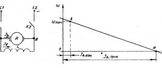
Another important operation that is necessarily included in the process of installing an electric motor is the alignment of the shafts that are connected to each other, as well as the mechanisms. This is done in order to completely eliminate the possibility of lateral and angular displacements of these parts.
When carrying out this operation, feelers, micrometers or indicators are used, with the help of which lateral and angular gaps are measured. It is very important to note here that when performing work using a probe, errors cannot be excluded. Its percentage depends directly on the worker who is engaged in measurements and on his experience. If the alignment was carried out correctly, then the numerical sum of the even measurements should coincide with the sum of the numerical value of the odd measurements.
Why center the motor shaft of pumping equipment?
The installation of electric motors for pumps is not too different from the installation of the same equipment. Here it is worth paying attention only to the alignment of the shafts. In this case, it is very important that the axes of both the motor shafts and the pump shafts coincide. If such work is not carried out, the risk of breakage of parts such as couplings or transmissions - gears or belts - increases greatly.
If we talk about the disadvantages of the belt drive in this case, then the belt itself will either constantly jump off or experience increased load, which will lead to faster wear. For example, if a well pump is installed with an electric motor, and they are connected using a half-coupling, then an excessive load will fall on the bearing, which will also cause it to fail very quickly. In any case, installation and maintenance of electric motors must always be accompanied by checking or adjusting the alignment of the shafts.
Installing an electric motor on a frame with a belt drive
There is also a belt drive (transmission). Most often, this method of mounting an electric motor is used when working with fans and some machines.
- We place the pulley on the electric motor shaft, while selecting the correct key for the keyway;
- with a belt drive, the electric motor is mounted on a skid;
- the electric motor should be installed on the slide so that the axes of the shafts of the electric motor and the driven mechanism are located horizontally and parallel to each other;
- the middle of one of the pulleys should be opposite the middle of the other pulley;
- it must be possible to adjust the belt tension as it is pulled out, especially during the first time of operation;
- the slides must be leveled parallel to one another and aligned in both longitudinal and transverse directions;
- the supporting surface under the slide must be continuous;
- To tension the belt, there must be bolts screwed into the movable stops.
You should watch the video on how to install an electric motor
Motor alignment methods for pumping equipment
Today there are many different ways to carry out this operation, but the most modern and accurate of them is the use of laser equipment. The use of these devices will make it possible to align the shafts of the electric motor and the shaft of pumping equipment or any other mechanism in the shortest possible time and most accurately. However, this method has one significant drawback - the high cost of equipment, which significantly complicates the use of this method. Because of this, the more traditional shaft alignment methods described earlier are often still used. It is worth adding here that before starting work, it is very important to decide what to adjust to what. In other words, you need to understand what is more convenient to adjust - the motor shaft to the pump shaft or vice versa.
Installing the electric motor on the frame
Well, then we install the electric motor on the frame. Most often, electric motors of pumping units and machine tools are installed this way.
- We place the coupling half on the electric motor shaft, while selecting the correct key for the keyway;
- install the engine on the frame, aligning the engine shaft with the equipment shaft in height and axis;
- We fasten the installed engine to the frame with bolts and nuts of the required size;
- we check all mechanical fastenings of the electric motor (bolts securing bearing shields, foundation bolts, etc.) and, if necessary, tighten them.
Installation work for a wound-rotor motor
Here it is immediately worth saying that the installation of an asynchronous electric motor with a wound rotor is similar to installation with a squirrel-cage rotor. The only difference is that for normal operation of the phase rotor, it is necessary to additionally carry out such work as starting the rheostat, checking the brushes and the brush lifting mechanism.
Before you begin installing the starting rheostat, you need to make sure that all contacts are secured securely enough. To do this, use a wrench to tighten all existing nuts. After this stage, you can proceed to checking the winding insulation, and how this is done was described earlier.
There are some nuances here. You can continue installation after checking the insulation resistance if the value is not lower than 1 mOhm. If this numerical value is lower, then it is considered reduced and you need to look for the cause of this defect. To do this, the integrity of all winding parts is usually checked, and you also need to make sure that the lead ends do not touch the motor housing. Another possible reason is dampness of the insulating plate, on which the fixed contacts are usually located. If this is the case, then it is necessary to carry out a drying procedure for all damp parts. For this, either a special drying cabinet or an electric lamp is used.
Slip rings and rotor
Installation of an asynchronous electric motor with a wound rotor or its repair, if required, is carried out with a mandatory check of the rotor winding, the output ends of the winding, slip rings and brushes must also be checked. It is very important to check the reliability of fastening of all wires, and in addition, the insulation resistance and the absence of breaks in the circuit are checked separately. This is all done using a megger.
After checking the insulation resistance value of the rings and winding, the numerical value should not be less than 0.5 mOhm. If the value is lower, then you will have to look for the reason for the decrease, and also check the resistance of each ring and winding separately. In this case, as in the previous one, the decrease may occur due to dampness of the windings of the rings or windings. In this case, you will have to dry it. However, if after this the resistance does not return to normal, then you will have to remove each ring separately and look for the reason for the decrease. It is prohibited to put into operation an electric motor with reduced resistance.