Current electricity prices make you think about saving where you never even thought about it before. For example, lighting on the stairs. It doesn’t matter if it’s in a private or multi-storey building, you still need to pay. Previously, they simply left the light on. Today you think about turning it off, but running up and down is also not fun. It turns out there is a solution. To prevent the lights from being on constantly, there are schemes for controlling the lamps from several places. That is, one or more lamps can be turned on and off from several points. Special switches are needed for this. They are called walk-throughs. Sometimes the names “duplicate” or “change-over” are found. All this is one type of electrical equipment. They differ from ordinary ones in a large number of contacts. Accordingly, the connection diagram for the pass-through switch is more complicated. However, you can figure it out.
What does a pass-through switch look like and work?
If we talk about the front side, the only difference is: a barely noticeable arrow on the up and down key.
What does a single-key pass-through switch look like? You see there are double arrows
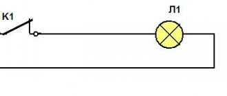
If we talk about the electrical circuit, everything is also simple: in ordinary switches there are only two contacts, in pass-through switches (also called changeover contacts) there are three contacts, two of which are common. There are always two or more such devices in the circuit, and they are switched using these common wires.
The difference is in the number of contacts
The operating principle is simple. By changing the position of the key, the input is connected to one of the outputs. That is, these devices have only two working positions:
- input connected to output 1;
- input is connected to output 2.
There are no other intermediate provisions. Thanks to this, everything works. Because the contact switches from one position to another, electricians believe it is more correct to call them “switches.” So a pass-through switch is also this device.
In order not to rely on the presence or absence of arrows on the keys, you need to inspect the contact part. Branded products should have a diagram on them that allows you to understand what type of equipment you have in your hands. It is definitely found on products from Lezard, Legrand, and Viko. They are often absent on Chinese copies.
This is what the changeover switch looks like from the rear
If there is no such diagram, look at the terminals (copper contacts in the holes): there should be three of them. But not always on inexpensive copies the terminal that stands alone is the input. They are often confused. To find where the common contact is located, you need to ring the contacts with each other at different key positions. This must be done, otherwise nothing will work, and the device itself may burn out.
You will need a tester or multimeter. If you have a multimeter, set it to sound mode - it beeps when there is contact. If you have a pointer tester, ring for a short circuit. Place the probe on one of the contacts, find which of the two it rings with (the device beeps or the arrow shows a short circuit - it deviates to the right all the way). Without changing the position of the probes, change the position of the key. If the short circuit is missing, one of these two is common. Now all that remains is to check which one. Without switching the key, move one of the probes to another contact. If there is a short circuit, then the contact from which the probe was not moved is the common one (this is the input).
It may become clearer if you watch a video on how to find the input (common contact) for a pass-through switch.
How to connect a hob is written here, and how to install and turn on a water heater is written in this article.
Useful information
Connection errors
At this stage of searching and connecting the main terminal in the pass-through switch, a mistake is made. For some reason, many people do not check the circuit and naively believe that the common terminal is the one with only one contact. If you assemble the circuit this way, the switches will not work correctly because they all depend on each other. Remember that on different switches the common contact can be anywhere! It is best to call it “live”, using an indicator screwdriver or tester. Most often, this problem can be encountered when replacing or installing switches from different companies. If everything worked previously, but after replacing the circuit it stopped working, it means you have the wires mixed up.
There may also be an option that the new switch is not passable at all. It is also important to remember that the lighting inside the product cannot affect the switching principle. Another popular mistake is the incorrect connection of crossover wires, when both cables from the first pass-through switch are seated on the top contacts, and from the second on the top. Meanwhile, cross switches have a slightly different switching mechanism and circuit, and the wires must be connected crosswise.
Flaws
The first drawback is that there is no specific position for the OFF or ON keys that the standard ones have. If a lamp burns out and needs to be replaced, then with such a circuit you may not immediately understand whether the light is on or off. It will be unpleasant when, when replacing, the lamp may simply explode near the eyes. In this case, the easiest and safest way would be to turn off the automatic lighting in the panel. The second disadvantage is the large number of connections in junction boxes. The more light points you have, the greater the number of light points in the distribution box. Connecting the cable according to diagrams without junction boxes will reduce the number of connections, but can increase either the cable consumption or the number of cores several times. If your wiring goes to the ceiling, then you will need to lower the wire from there for each switch, and then raise it up. The best option here is to use a pulse-type relay.
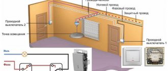
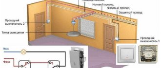
Connection diagram for a pass-through switch from two places
This scheme is convenient in a two-story house on the stairs, in a passage room, in a long corridor. You can also use it in the bedroom - turn off the overhead light at the entrance and near the bed (how many times did you have to get up to turn it on/off?).
Electrical diagram for switching on a pass-through switch from 2 places
Zero and ground (if any) are connected directly to the lamp. The phase is supplied to the output of the first switch, the input of the second is connected to the free wire of the lamp, the outputs of the two devices are connected to each other.
Looking at this diagram, it is easy to understand how the pass-through switch works. In the position shown in the figure, the lamp is on. By pressing the key of any of the devices, we break the chain. In the same way, when in the off position, by moving any of them to another position, we will close the circuit through one of the jumpers and the lamp will light up.
To make it clearer what to connect to what, and how to lay the wires, here are a few images.
Connecting wires on a pass-through switch
If we talk about the room, then you need to lay the wires approximately as in the photo below. According to modern rules, all of them should be located at a distance of 15 cm from the ceiling. They can be placed in mounting boxes or trays; the ends of the wires are inserted into mounting boxes. This is convenient: if necessary, you can replace a broken wire. Also, according to the latest standards, all connections occur only in installation boxes and using contactors. If you make twists, it is better to solder them and wrap them well with electrical tape on top.
The return wire of the lamp is connected to the output of the second switch. White indicates the wires connecting the outputs of both devices.
How to route wires around the room
How to connect everything in the terminal box is described in the video.
Read how to connect the chandelier yourself here.
Pros and cons of controlling from multiple points
The main advantage of the decision to connect 2 switches to 1 light bulb is the increased level of comfort. This scheme allows you to avoid wasting time returning to the installation site of the switching device in order to deactivate the lighting. Also, the use of this control principle allows you to save energy by reducing the operating time of lighting elements.
There are few disadvantages to such a system, but the main one is that it is impossible to determine from the position of one switch whether voltage is supplied to the lamps . Also, the disadvantages include the need to make additional technical solutions if priority control of light from the central console is necessary.
3 point circuit
To be able to turn the light on/off from three places, you need to buy a cross (cross) switch for two switches. It differs from those described earlier by the presence of two inputs and two outputs. It switches a couple of contacts at once. See the figure for how everything should be organized. If you understand the above, this one is easy to understand.
Electrical circuit for controlling a lamp from three points
How to assemble such a circuit? Here's the procedure:
- Zero (and ground, if any) is connected directly to the lamp.
- The phase is connected to the input of one of the pass-through switches (with three inputs).
- The input of the second is fed to the free wire of the lamp.
- The two outputs of one three-pin device are connected to the input of a crossover switch (with four inputs).
- The two outputs of the second three-pin device are connected to the second pair of switch contacts with four inputs.
The same diagram, but from a different perspective - where to connect the wires on the housings.
Where to connect the wires
And this is approximately how to distribute it around the room.
Wiring when controlling the lamp from three places
If you need a circuit with four, five or more points, then it differs only in the number of cross switches (for four inputs/outputs). There are always two switches (with three inputs/outputs) in any circuit - at the very beginning and at the very end of the circuit. All other elements are cross devices.
Connection diagram for pass-through switches for 5 points
Remove one “crossbar” and you get a four-point control scheme. Add more and there will be a scheme for 6 control places.
To finally get it all in your head, watch this video.
Read about the rules for connecting wires in a junction box here.
Two-key pass-through switch: connection diagram
To control the lighting of two lamps (or groups of lamps) from one switch from several places, there are two-key pass-through switches. They have six contacts. If necessary, find the common wires using the same principle as in a conventional device of this type, only you will have to connect a larger number of wires.
The connection diagram for a 2-key pass-through switch differs only in that there will be more wires: the phase must be supplied to both inputs of the first switch, just as from the two inputs of the second it must go to two lamps (or two groups of lamps, if we are talking about a multi-arm chandelier ).
The principle of connecting two-key pass-through switches
If you need to organize control of two light sources from three or more points, you will have to install two cross switches at each point: there are simply no two-key switches. In this case, one pair of contacts is placed on one crossbar, the second on the other. And then, if necessary, they are connected to each other. The outputs of both crossbars are connected to the last two-key transition switch in the chain.
How to organize control of two lamps from four places
If you think about it, everything is not so complicated, and the connection diagram for a pass-through switch from 2 points is generally simple. Just a lot of wires...
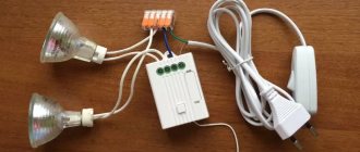
Using an impulse relay
The pass-through circuit can also be organized using a pulse relay.
What are the benefits?
The main advantage of this scheme is the unlimited number of control points. Each switch requires only two wires.
What are the disadvantages?
You need an installation location in the panel, and accordingly you will have to run all the wiring there.
push-button type
switches as switches . In general, such a solution is acceptable only with a large number of lighting control locations or for any non-standard tasks.
There are many models of pulse relays and in general the issue requires a separate topic, so the details will not be considered within the framework of this publication.