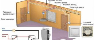
A single-key pass-through switch is necessary to control one circuit or lighting line from several points located in different parts of the room or the entire house. That is, with one switch you turn on the lighting when entering a room or corridor, and with another, but at a different point, you turn off the same lighting.
Very often this is used in bedrooms. I went into the bedroom and turned on the light near the door. I lay down on the bed and turned off the light at the headboard or near the bedside table. In two-story mansions, he turned on the light bulb on the first floor, climbed the stairs to the second and turned it off there.
Selection, design and differences of pass-through switches
Before assembling such a control scheme, here is what you should pay special attention to:
1To connect a pass-through light switch,
a three-core cable is required - VVGng-Ls 3*1.5 or NYM 3*1.5mm2
2Do not try to assemble a similar circuit using ordinary switches.
The main difference between regular and pass-through ones is the number of contacts. Simple single-key ones have two terminals for connecting wires (input and output), while pass-through ones have three!
In simple terms, the lighting circuit can be either closed or open, there is no third option.
It is more correct to call a pass-through not a switch, but a switch.
Since it switches the circuit from one working contact to another.
In appearance, from the front they can be absolutely identical. Only the pass key can have an icon of vertical triangles. However, do not confuse them with reversible or crossover ones (more about them below). These triangles point in a horizontal direction.
But from the reverse side you can immediately see the difference:
- the pass-through has 1 terminal on top and 2 on the bottom
- a regular one has 1 on top and 1 on the bottom
Due to this parameter, many people confuse them with two-key ones. However, two-key ones are also not suitable here, although they also have three terminals.
The significant difference is in the operation of the contacts. When one contact is closed, pass-through switches automatically close the other, but two-key switches do not have such a function.
Moreover, there is no intermediate position when both circuits are open at the gateway.
Three mounting options for single-key switches
Let's look at three switch connection diagrams that are similar in design (have one button), but differ in the type of installation. Also, all options are united by the basic law of introducing single-key models: the dynamic element opens the “phase” and not the “zero”. Otherwise, there may be a risk of injury during repair work and even when simply replacing lamps.
#1: Photo instructions for installing an outdoor device
The location of the wires for this connection diagram is not of fundamental importance: they can run along the surface or be inside the wall. An external type of switch in a residential area is welcome if expensive repairs have just been made and there is no desire to tear down the walls and install ducts again.
The simplest connection diagram for a single-key switch, which serves as the basis for practical actions for novice electricians: wire L (phase) goes to the switch, the rest - directly to the light source
We will consider the option of external cable laying, in which the wires are enclosed in a corrugated protective channel.
At the location where the switch is installed, the corrugated pipe, fixed to the wall with special clips, is cut across, and the working insulated wire is taken out.
Under the switch there will be another electrical device - a socket, so the cables for both devices are enclosed in one corrugation for aesthetic reasons.
The power cable associated with the outlet will pass through the surface-mounted switch, so as not to make a loop and not to increase the installation area
The selected switch model - Schneider Electric - has a plastic case and IP44 protection degree. Before installation, we take safety measures: turn off the power to the cable at the electrical panel installed on the site or in the corridor.
To make sure there is no voltage in the cable, use an indicator screwdriver. When the issue of turning off the power is resolved, we begin disassembling the switch.
First, we take out the key with our hand - this is done quite easily.
Under the key that closes the switch from above, there is another plastic protective strip - the front panel, which also needs to be removed by carefully pressing out the holders
The next step is to remove the working mechanism.
The mechanism that closes/opens the electrical circuit is not secured with special holders or springs, so it can be reached quickly and without problems
Now you need to accurately determine the location of installation of the switch and mark on the wall the points for screwing in the fasteners. To do this, take an already empty case and attach it to the wall.
We level it and use a marker to mark the points for drilling. Using a drill, we drill holes for fastening (another fastening method is also possible).
We fix the plastic case in a designated place on the wall using dowels - the best option for fixing on concrete and brick bases
We remove the elastic plug located in the upper part from the switch body, insert the wires into the hole and the end of the corrugated pipe coming from the ceiling.
The result should be a neat, tight connection between the corrugation and the body with free access to the wires for further work.
Time to start connecting directly. We remove the insulating material from the ends of the wires and strip 8-10 mm.
We connect the white wire (phase) to the terminal marked L, the blue wire to the other terminal marked “1”. Carefully tighten the bolts and place the working unit into the housing.
We lay the wire leading to the socket around the working unit and bring it out into the lower hole of the housing, and insert the second end of the corrugated pipe there
We reassemble the switch: put the front panel in place, then fix the key.
At the end of the work, we carry out testing: turn on the power supply and press the key several times. If the lighting device lights up when turned on, the connection is made correctly
It is quite easy to install the switch yourself, even if the installation is complicated by the presence of additional devices.
However, if you are not sure of the correctness of actions, it is better to play it safe and make the first connection under the supervision of an experienced electrician.
#2: Master class on replacing an old switch
Often, in connection with renovations in an apartment or private house, it is necessary to dismantle the old switch and install a new, more modern and convenient one in its place.
Let's look at the main stages of replacing a switch, using step-by-step photographs of the process.
Before us is an old, unsightly model of a built-in switch installed inside the concrete base of a panel house. It is necessary to remove it by unscrewing the two mounting bolts
Using a screwdriver, unscrew the screws and remove the plastic cover.
Under the cover is the old connection mechanism, in which the cores are fixed with a bolted connection. Bolts are visible on the left, and metal fastening “ears” on both sides.
Our task is to determine the “phase”.
To find the working wire, we use a voltage indicator, which is usually an indicator screwdriver with a light signal
We bring the screwdriver to the contacts one by one, never touching them with our hands (it is better to use insulating gloves). For an accurate determination, set the key in both positions.
When the “phase” position is off, only one contact will be energized. The second wire is for the lighting fixture.
Having established the purpose of the wires, we turn off the electricity supply, check the presence or absence of voltage and, having made sure that it is safe, we begin to disassemble the old switch. We unscrew the fasteners of the metal holders (“claws”) and take out the working unit.
Carefully disconnect and isolate the wires: first the “phase”, then the second wire. For insulation, it is better to use electrical tape of different colors so as not to make mistakes when connecting
We finally release the mechanism, straighten the wires - the place for the new switch is prepared. We take a new product, purchased in advance, and prepare it for installation, in other words, we disassemble it.
We remove the key, unscrew the protective panel and see the internal mechanism - with two mandatory clamps and spacer holders.
The screws located at the edges regulate the movement of the “legs”, and those located on top are used to connect wires - they are the ones that regulate the contact pressure plate
We strip the ends of the wires about 1 cm, insert them into the holes located under the upper screws, making sure that the winding does not slip inside along with the exposed wire. We tighten it tightly so that the wires do not move.
If the holes are marked, insert the “phase” into the hole marked “L”, the outlet wire – “1”. Instead of the indicated designations, there may be numbers “1” and “2” - then the “phase” will go to “1”
Having connected the wires, we insert the working unit into the installation box.
To prevent the mechanism from “walking” inside the socket, we fix it using metal holders, tightly tightening the side fastening screws
Install the top panel and fix the key.
We test the operation of the device, although it is better to carry out the first check before the internal mechanism is fully secured - so as not to have to redo it
So, to install the new switch we needed tools (screwdriver, pliers, knife, wire cutters, indicator screwdriver), some insulating material and 20 minutes of time. Calling an electrician would cost about 500 rubles.
Connecting a pass-through switch
First of all, you need to correctly connect the switch itself in the socket box. Remove the key and the overhead frames.
When disassembled, you can easily see the three contact terminals.
The most important thing is to find the common one. On high-quality products, a diagram should be drawn on the reverse side. If you understand them, you can easily navigate through it.
If you have a budget model, or any electrical circuits are a bit of a mystery to you, then an ordinary Chinese tester in circuit continuity mode, or an indicator screwdriver with a battery, will come to the rescue.
Using the tester's probes, alternately touch all the contacts and look for the one on which the tester will “squeak” or show “0” at any position of the ON or OFF key. It's even easier to do this with an indicator screwdriver.
After you have found the common terminal, you need to connect the phase from the power cable to it. Connect the remaining two wires to the remaining terminals.
Moreover, which one goes where does not make a significant difference. The switch is assembled and secured in the socket box.
Do the same operation with the second switch:
- look for the common terminal
- connect the phase conductor to it, which will go to the light bulb
- connect two other wires to the remaining ones
Why is a “phase” connected to the breaker break?
In accordance with clause 6.6.28 of the PUE, a requirement is established that any phase conductor switch must be connected to the break. Which is due to the following phenomenon:
Rice. 8. Connecting the neutral conductor to the gap of a two-key switch
If it is necessary to replace a failed electric lamp, you can turn off the switch key and begin dismantling and installing new equipment. But, as shown in the figure, when the switch is turned off, its contacts will break the neutral conductor. And the voltage from the phase conductor will flow freely to the lamp socket. If you touch exposed live parts, a person will receive an electric shock, which can lead to electrical injury and even death.
Changeover switches - lighting control circuit from 3 places
But what if you want to control one lighting from three or more points. That is, there will be 3, 4, etc. switches in the circuit. It would seem that you need to take another pass-through switch and that’s it.
However, a switch with three terminals will no longer work here. Since there will be four connected wires in the junction box.
Here a changeover switch, or as it is also called a cross, cross, or intermediate switch, will come to your aid. Its key difference is that it has four outlets - two at the bottom and two at the top.
And it is installed precisely in the gap between two passageways. Find in the junction box two secondary (not main) wires from the first and second pass-through switch.
You disconnect them and connect a changeover between them. Connect the wires that come from the first to the input (follow the arrows), and those that go to the second to the output terminals.
Always check the diagram on the switches! It often happens that their entrance and exit are on the same side (top and bottom). For example, the connection diagram for a Legrand Valena changeover switch:
Naturally, there is no need to stuff the changeover itself into the junction box. It is enough to lead the ends of a 4-core cable from it there. Meanwhile, you place the switch itself in any convenient place - near the bed, in the middle of a long corridor, etc. You can turn the light on and off from anywhere.
The most important advantage of this circuit is that it can be changed indefinitely and add as many changeover switches as you like. That is, there will always be two passing ones (at the beginning and the end), and in the interval between them there will be 4, 5 or at least 10 crossover ones.
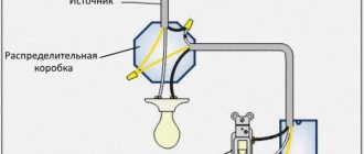
General provisions
Next, we will consider the most common schemes for powering the lighting elements of a room.
The features of creating such branches largely depend on the number of lamps connected to them, as well as their control using a switch.
But in any case, the created branch includes:
- Switch (one-, two-, three-key);
- Lamps with sockets;
- Junction box;
- Wires (two- and three-core).
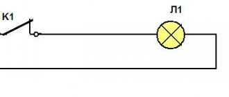
A little about the features of the breaker.
Any switch has two outputs - input and output (there may be several of the latter).
Moreover, both of them belong to the same line, that is, if a phase is connected to the input terminal, then it will also be at the output.
By moving the key to a certain position, the contacts of these terminals are connected or disconnected, thereby closing or opening the circuit.
Safety precautions.
Before describing connection methods, let us immediately remind you of safety precautions when carrying out work.
To avoid electric shock, turn off the power supply and take steps to prevent accidental restoration of power before work is completed.
Its supply should be restored only after complete installation and connection of all components of the branch, as well as ensuring reliable insulation of the wire connection points.
Read on: is it worth using aluminum wiring?
Connection errors
Many people make a mistake at the stage of searching and connecting the common terminal in the pass-through switch. Without checking the circuit, they naively believe that the common terminal is the one with only one contact.
They assemble a circuit in this way, and then for some reason the switches do not work correctly (they depend on each other).
Remember that on different switches the common contact can be anywhere!
And it is best to call it, what is called “live”, with a tester or an indicator screwdriver.
Most often, this problem is encountered when installing or replacing pass-through switches from different companies. If everything worked before, but after replacing one circuit the circuit stopped working, it means the wires were mixed up.
But there may also be an option that the new switch is not pass-through at all. Also remember that the lighting inside the product cannot in any way affect the switching principle itself.
Another common mistake is connecting the crossovers incorrectly. When both wires are placed from pass-through No. 1 to the upper contacts, and from No. 2 to the lower ones. Meanwhile, the cross switch has a completely different circuit and switching mechanism. And you need to connect the wires crosswise.
Placement - convenience and safety
Before installing the switch, you should consider the most convenient location for installation and subsequent use. The most advantageous area is located near the entrance doors (from the side of the door handle), but there may be exceptions (for example, next to the head of the bed).
Before drawing up a wiring project, it is better to look at the official document - PUE (electrical installation rules), which regulates some of the nuances of installation. For example, clause 7.1.48 states that the switch must be located at least 60 cm from the shower stall, and clause 7.1.50 allows it to be installed no closer than 50 cm from the gas pipeline.
As can be seen from the installation diagram, the distance from the doors to the installation point must be at least 10 cm, and to the floor - at least 90 cm
The installation of control devices in bathrooms and saunas is prohibited; they must be taken outside the room (usually into the corridor).
Sensory Modifications
Currently, owners of apartments and private houses are increasingly using touch switches to furnish their premises. The line of this type of product also includes touch-sensitive pass-through switches .
The devices not only increase the level of comfort, but are also stylish design elements.
Touch switches in the interior
Below we provide some connection diagrams for touch pass-through switches.
Connection diagram for two pass-through touch switches
Connection diagram for three pass-through touch switches
To learn how to connect and sync pass-through touch switches, you can watch the video below.
Circuit solutions for practical operation
The most commonly used circuits for connecting pass-through devices are, as a rule, circuits for one-, two-, and three-key devices. The single-key option was discussed above.
Schematic version of the system design for five control points. Three two-key switches and two one-key switches are used here: N – network zero; L – network phase; 1, 2 – switches; p - jumpers
Therefore, let’s see what the step-by-step instructions for connecting a two-key device look like.
- It is necessary to schematically outline the installation of the system.
- Carry out work on installing the switchgear and socket boxes.
- Install the required number of light groups.
- Lay out the network taking into account the supply of phase, neutral, and grounding conductors.
- Connect the separated conductors according to the drawn diagram.
Attention should be paid not only to purely electrical installation work, but also to technical work. For example, it is recommended to pay great attention to the installation of socket boxes.
These elements must be securely fastened to the wall so that in the future they provide no less reliable fastening of the devices.
There is a three-point communication system, which is based on creating a system that allows you to control a light group of three points separated at a distance. The elemental base consists of three devices, of which two are two-key through and one is cross-type.
A widespread version of the three-point circuit: N – electrical zero; L – electrical phase; PV1 – first two-key switch; PV2 – second two-key switch; PV3 – crossover switch
A kind of connection instruction in this case looks something like this:
- A wiring and connection diagram is created.
- Work is underway to install the distribution box and socket boxes.
- Three-core electrical cables are laid in the amount of 4 pieces.
- Electrical installation is carried out - connection according to the diagram.
This option for creating a communication power network looks somewhat complicated. As is clear even from laying the cables, you will have to deal with a total of 12 conductors. Regular pass-through switches require 6 wires, while a crossover switch requires 8 wires.
A phase line is connected to the common terminal of any of the two-key switches. The line of the light group is connected to the common line of the second two-key switch. The remaining conductors are connected according to the contact numbers according to the schematic diagram.