The electrical parameters of some elements can be displayed directly in the document, or presented separately in the form of a table. The control conductors of a contactor or starter are connected to this dry contact, the function of which is to switch or disconnect phase wires, protecting the system from dangerous voltage surges. Thus, it turns out that when the relay is turned off, the contacts are closed. Sometimes you can hear such a document called a power supply diagram; this is incorrect, since the latter shows how consumers are connected to a substation or other power source.
Examples of UGO in functional diagrams Below is a drawing depicting the main components of automation systems. Let's look at this in more detail. How to read electrical diagrams The spring contact itself is fixed to the yoke.
It is convenient to draw lamps in AutoCAD using dynamic blocks.
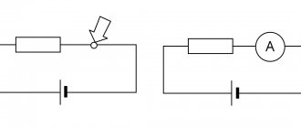
This is the electromagnetic relay K1 itself, the switch SA1 and the power battery G1. Each of the designations can be used in certain cases.
In most cases, the relay is mounted in a protective housing. D - contacts of switching devices:.
Reading electrical circuit diagrams
Relay protection marking
DC electromagnetic relay
To indicate relay protection, markers of machines, instruments, devices and the relay itself are used in the drawings. All devices are depicted in conditions without voltage in all power lines. According to the type of purpose of the relay device, three types of circuits are used.
Schematic diagrams
The schematic drawing is carried out along separate lines - operating current, current, voltage, alarm. The relays on it are drawn in dissected form - the windings are on one part of the picture, and the contacts are on the other. There are no markings of internal connections, clamps, or operating current sources on the circuit diagram.
Complex connections are accompanied by inscriptions indicating the functionality of individual components.
Wiring diagram
Example of a wiring diagram
Marking of protection devices is carried out on working diagrams intended for the assembly of panels, control or automation. All devices, clamps, connections or cables reflect the connection details.
The wiring diagram is also called the executive diagram.
Structural diagrams
Allows you to highlight the general structure of relay protection. The nodes and types of mutual connections will be indicated. To mark organs and nodes, rectangles with inscriptions or special indices are used to explain the purpose of using a particular element. The structural diagram is also supplemented with symbols of logical connections.
Purpose of the device
The high load experienced by electric motors causes an increase in electricity consumption during operation. This often leads to exceeding the standard operating parameters of the equipment. An overload in an electrical circuit causes a rapid rise in temperature. And this, in turn, causes malfunctions and accidents.
The purpose of the thermal relay is to create the prerequisites for maintaining normal operating conditions through the possibility of turning off power in case of overload and risk of accident.
This device closes or opens a circuit based on a signal from the unit, depending on the current operating temperature. As a result, the electric motor is protected from current overloads.
Among the advantages of this device are:
But this will require periodic performance testing and configuration.
Symbol
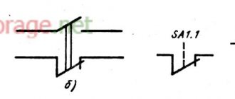
On an electrical diagram, a relay is usually denoted by a rectangle, from the large sides of which lines of solenoid power terminals extend.
Graphic markers
Relay symbols on diagrams
The graphical method of depicting elements is implemented using geometric shapes:
- contacts – similar to switch contacts;
- devices with contacts near the coil - dashed line connection;
- contacts in different places - serial number next to the rectangle;
- polar relay - a rectangle with two terminals and a dot near the connector;
Relay contact group - fixation of the switch when triggered - a bold dot at the fixed contact;
- closed relay contacts after the voltage has been removed - a circle is drawn on the designation of a closed or open contact;
- magnetically controlled contacts (reed switch) in the housing - circle;
- number of windings – inclined lines;
- moving contact – arrow;
- single-line conductive surface - a straight line with branch terminals;
Polarized relay - annular or cylindrical current-carrying surface - circle;
- jumpers (relay as a voltage divider) for cutting the network - a line with detachable connection symbols;
- switching jumper – U-shaped bracket.
Relay contacts can be signed.
Letter designation
A UGO relay is sometimes not enough to correctly read the circuit. In this case, a letter marking method is used. The relay code is the English letter K. For a clear understanding of what a letter on a relay diagram can mean, you should refer to the table.
| Letters | Decoding |
| A.K. | Block relay/protective complex |
| AKZ | Resistance relay kit |
| K.A. | Current relay |
| KAT | R. current with BNT |
| KAW | R. current with braking |
| KAZ | Current relay with filter functions |
| K.B. | R. lock |
| KF | R. frequencies |
| KH | Index |
| KL | Intermediate |
| F | Fuse |
| XN | Permanent connection |
| XT | Separable connection |
| KQC | Relay "on" |
| KQT | Relay "off" |
| KT | R. time |
| KSG | Thermal |
| KV | R. voltage |
| K 2.1, K 2.2, K 2.3 | Contact groups |
| XT | Terminals |
| E | Elements to which the relay is connected |
| NO | Normally open contacts |
| NC | Normally closed contacts |
| COM | General (switching) contacts |
| mW | Power consumption |
| mV | Sensitivity |
| Ω | Winding resistance |
| V | Voltage rating |
| mA | Rated current |
Letters can be used on a graphic diagram.
Rules for the design of electrical circuit diagrams
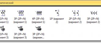
Currently, the electrical circuit diagrams of transformer substations are carried out in accordance with GOST 21.613–88. The normally off position of the switch corresponds to a shaded rectangle, and an unshaded rectangle corresponds to the switch being on. The switch can be designated using the letter code Q without the automatic shutdown feature F.
Conventional graphic designations on the diagrams should be carried out on the basis of the recommendations of GOST 2.721–74*, given in the appendix. A.
The issues of placing electrical equipment in domestic premises, workshops, substations, etc. are often considered. Conventional graphic images based on GOST 21.614–88 are given below.
It is recommended to place electric power facilities on terrain maps and situational maps, designate objects and communication lines between them in accordance with the graphic symbols below.
Designations depending on relay types
Depending on the type, relay devices may be designated differently on the diagrams.
Thermal Relay Models
Thermal protection relays are used to ensure normal operation of consumers. The devices turn off the electric motor instantly or after some time, preventing damage to the insulating surface or individual components.
In the diagrams, the thermal relay is designated as KSG and is connected to a normally closed contact. The connection is made using the TR system - to the output of the low-voltage electric motor starter.
Thermal relay cost
Time relay
Designation of a time relay
The time relay is designated as KT and works on the principle of pausing under a certain influence. The device may also have cyclic activity.
To designate contacts operating for closure in accordance with GOST 2.755-87, the following are used:
- arc down – delay after voltage is applied;
- arc down – contact triggered upon return;
- two arcs in the opposite direction - a delay in applying and removing control voltage.
Pulse normally open contacts are designated as follows:
- a dash at the bottom with a diagonal angular line and an arrow without a lower part - pulse closure when triggered;
- a dash at the bottom with a diagonal corner line and an arrow without an upper part - pulse closure during return;
- a dash at the bottom with a diagonal angular line and a normal arrow - a pulse closure at the moment of operation and return.
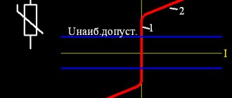
The supply voltage supplied to the time relay is marked in the diagrams as a blue graph. The direction of voltage to the devices is indicated as a gray graph. The response delay range is indicated by red arrows. The time interval is represented by the letter T.
Time relay cost
Current relay
Current relay in the diagram
The current relay controls current and voltage. An increase in the first parameter indicates a problem with the equipment or line.
On the diagrams, the device is marked as KA (the first letter is common for relays, starters, contactors, the second is specific for the current model). If BNT is present, it will be designated KAT, braking – KAW, filtration – KAZ. The coil in the drawings is depicted as a rectangle, the size of which is 12x6 mm. Contacts are designated normally open or normally closed.
The voltage winding is marked as a rectangle divided into two parts horizontally. The smaller one indicates the letter U; from the larger one, straight lines are directed horizontally up and down.
The current winding is indicated as a rectangle divided into two sectors in the horizontal direction. In the larger one, there are two lines horizontally at the top and bottom. On the smaller one, the letter I is written with a greater symbol (maximum current).
Current relay cost
Features of the designation of electromagnetic relays on diagrams
Structurally, an electromagnetic relay is an electromagnet with one or more contact groups. Their symbols form the UGO of the device. The electromagnet winding is drawn as a rectangle with lead lines on both sides. Contact markers K are located opposite the narrow side of the winding and are connected by a dotted line (mechanical connection).
The contact pin can be depicted on one side, and the contacts - near the switching UGO. The assignment of contacts to a specific relay is indicated in the form of serial numbering (K 1.1., K 1.2).
Parameters or design features can be indicated inside the rectangle. For example, in the symbol K 4 there are two oblique dashes, i.e. The relay has two windings.
To distinguish them from standard devices, modifications with magnetically controlled contacts in a sealed housing are indicated by a circle. This is the reed switch symbol. The belonging of an element to a specific device is written in the form of contact letters (K) and serial numbers (5.1, 5.2).
The reed switch, controlled by a permanent magnet and not included in the relay protection design, has a circuit breaker coding - SF.
Electromagnetic relay cost
Intermediate relay
Intermediate relay in the diagram
Intermediate relay devices are used for switching electrical circuits. They amplify the electrical signal, distribute electricity, and interface radio elements. The symbol of the coil is a rectangle with the letter K and a serial number in the drawing.
The designation of the intermediate relay contacts in the diagram is done using a letter, but with two numbers, which are separated by a dot. The first indicates the serial number of the relay device, the second indicates the number of the group of contacts of this device. The contacts located near the coil are connected by hatching.
The marking of the electrical circuit and terminals is carried out by the manufacturer. It is applied to the lid covering the working parts. The contact parameters are written under the diagram - the maximum switching current. Some brands number the pins on the sides of the connection.
The diagrams show the contacts in a state without voltage supply.
Cost of intermediate relay
Current-carrying, switching, lighting equipment
Table. Conventional graphic images of electrical equipment and wiring on plans. Excerpt from GOST 211.614–88.
| Name | Image | Size, mm | |
| 1 | 2 | 3 | |
| Wiring and conductor lines | |||
| Wiring line (general image) It is allowed: to indicate wiring data above the line image (type of current, voltage, material, installation method, wiring mark, etc.); indicate the number of conductors in the line with serifs | Thickness 1.0 | ||
| Examples | Same | ||
| 110V DC circuit | |||
| line consisting of three conductors | |||
| Control line | |||
| Emergency evacuation and security lighting network line | |||
| Line voltage 35 V and below | |||
| Grounding and grounding line | |||
| Grounding switches | |||
| Metal structures used as grounding and grounding lines | |||
| Laying wires and cables | |||
| Open laying of one conductor | Thickness 1.0 | ||
| Open routing of multiple conductors | |||
| Open laying of one conductor under the ceiling | |||
| Open laying of several conductors under the ceiling | |||
| Laying on the cable and its end fastening | |||
| Wiring in the box | |||
| Wiring in the box | |||
| Vertical wiring | |||
| Posting goes to a higher level or comes from a higher level | |||
| The posting goes to a lower level or comes from a lower level | |||
| The wiring crosses the mark shown on the plan from top to bottom or bottom to top and does not have horizontal sections within this plan | |||
| Wiring in pipes (general image) | |||
| Wiring in a pipe through the wall | |||
| Wiring in the pipe through the ceiling | |||
| Laying busbars and busbars (general image) | Thickness 2.0 | ||
| Busbar laid in insulators | Diameter 5.0 | ||
| Bus or busbar on racks | Diameter 4.0 | ||
| Bus or busbar on suspensions | |||
| Busbar or busbar on brackets | |||
| Trolley line | |||
| Trolley line sectioning | |||
| Trolley line sectioning | Radius 2.5 | ||
| Boxes, panels, boxes with equipment, cabinets, panels, consoles | |||
| Branch box | Diameter 5.0 | ||
| Introductory box | |||
| Main panel for working lighting | |||
| Panel of group working lighting | |||
| Group emergency lighting panel | |||
| Equipment box | |||
| Cabinet, panel, remote control, one-way service panel, local control station | |||
| Cabinet, two-way service panel | |||
| Cabinet, panel, remote control, panel made of several panels for one-way service. Example: panel of four cabinets | |||
| Cabinet, panel, remote control, panel made of several panels for double-sided service. Example: panel of five cabinets | |||
| The shield is open. Example: panel of four control panels | |||
| Switches, switches and sockets | |||
| Switch (general designation) | Diameter 2.0 | ||
| Switch for surface installation with degree of protection from IP20 to IP23: | |||
| single-pole | Same | ||
| single pole double | Same | ||
| single-pole triple | Same | ||
| bipolar | Same | ||
| three-pole | Same | ||
| Switch for concealed installation with degree of protection from IP20 to IP23: | |||
| single-pole | Diameter 2.0 | ||
| single pole double | Same | ||
| single-pole triple | Same | ||
| bipolar | Same | ||
| Switch for surface installation with degree of protection from IP44 to IP55: | |||
| single-pole | Diameter 2.0 | ||
| bipolar | Same | ||
| three-pole | Same | ||
| Two-way switch without zero position with degree of protection from IP20 to IP23: | |||
| single-pole | Diameter 2.0 | ||
| bipolar | Same | ||
| three-pole | Same | ||
| Two-way switch without zero position with degree of protection from IP44 to IP55: | |||
| single-pole | Same | ||
| bipolar | Same | ||
| three-pole | Same | ||
| Plug socket (general picture) | |||
| Surface-mounted socket with degree of protection from IP20 to IP23: | |||
| bipolar | Same | ||
| bipolar double | Same | ||
| two-pole with protective contact | Same | ||
| three-pole with protective contact | Same | ||
| Recessed socket outlet with degree of protection from IP20 to IP23: | |||
| bipolar | |||
| bipolar double | Same | ||
| two-pole with protective contact | Same | ||
| three-pole with protective contact | Same | ||
| Plug socket with degree of protection from IP44 to IP55: | |||
| bipolar | Same | ||
| two-pole with protective contact | Same | ||
| three-pole with protective contact | Same | ||
| Units with switches and two-pole sockets for surface installation with degrees of protection from IP20 to IP23: | |||
| one switch and plug socket | Same | ||
| two switches and a plug socket | Same | ||
| three switches and a plug socket | Same | ||
| Units with switches and two-pole plug socket for flush installation with degree of protection from IP20 to IP23: | |||
| one switch and plug socket | Same | ||
| two switches and a plug socket | Same | ||
| three switches and a plug socket | Same | ||
| Lamps and spotlights with separate images on the plan of equipment and electrical networks | |||
| Lamp with incandescent lamp (general designation) | |||
| Luminaire with fluorescent lamp (general designation) | |||
| Luminaire with high pressure discharge lamp. | |||
| Spotlight, e.g. with incandescent lamp (general designation) | |||
| Incandescent lamp for emergency lighting | |||
| Luminaire with fluorescent lamp for emergency lighting | |||
| Fixture with incandescent lamp for special lighting (light indicator), e.g. for emergency exit | |||
| Lamps and spotlights with separate images on the plan of equipment and electrical networks | |||
| Lamp with incandescent lamp (general designation) | Diameter 5.0 | ||
| Lamp with incandescent lamp on a cable | Diameter 5.0 | ||
| Lamp with an incandescent lamp on a bracket, on the wall of a building, structure for outdoor lighting | |||
| Lamp with fluorescent lamps. Note: it is allowed to depict a lamp with fluorescent lamps to the scale of the drawing | |||
| Lamp with fluorescent lamps installed in a line | |||
| Luminaire with fluorescent lamp on a bracket for outdoor lighting | |||
| Luminaire with high pressure discharge lamp on bracket for outdoor lighting | |||
| Luminaire with high pressure discharge lamp on pole for outdoor lighting | Same | ||
| Chandelier | Same | ||
| Lamp – slotted light guide | |||
| Spotlight | |||
| A group of spotlights with the optical axis directed in one direction | |||
| A group of spotlights with the optical axis directed in all directions | Diameter 6.0 | ||
| Control equipment | |||
| Starting device for electric motors (general image) | |||
| Magnetic switch | |||
Table. Conventional graphic images of electrical equipment and wiring on plans. Excerpt from GOST 21.614–88. Conditional images
| Name | Image |
| Electrical devices and electrical receivers | |
| Electrical device (general image) | |
| Electrical device, for example with an electric motor | |
| Multi-motor electric drive device | |
| Device with generator | |
| Engine - generator | |
| Complex transformer device with one transformer. Note: it is allowed to depict a low-power transformer without a rectangular contour | |
| The same with several transformers | |
| Complex condenser installation | |
| Complex converting installation | |
| Accumulator battery | |
| Electric heating device (general designation) | |
| Electrical equipment of open switchgears | |
| Power transformer: | |
| oil with expansion tank | |
| oil without expansion tank | |
| Oil switch, voltage: | |
| 6…10 kV | |
| 35 kV | |
| 110… 220 kV | |
| Disconnector, separator voltage 35, 110, 220 kV | |
| Short circuit, grounding switch voltage 35, 110, 220 kV | |
| Automatic high speed switch | |
| Concrete reactor | |
Normally closed
The algorithm of their work is exactly the opposite. The contacts are closed when the relay is de-energized, and are switched off when voltage appears on the winding. This is used when implementing various interlocks and in signaling circuits. A typical example of the use of normally closed contacts is a mechanical relay regulator. We'll talk briefly about his work below.
Through normally closed contacts, voltage is supplied to the excitation winding. Accordingly, when the armature is released, the generator generates electric current. The battery is being recharged. As soon as the voltage in the on-board network exceeds the set value, the armature is attracted, the relay-regulator contacts are released, and the excitation winding is de-energized. As a result, the voltage at the generator output decreases.
By the way, despite the fact that electronic relay regulators appeared a long time ago, owners of old cars are in no hurry to install them instead of mechanical ones. This is due to the trouble-free operation of the latter for many years. This is about the issue of reliability.
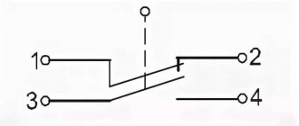
What are contacts
In relation to relays, this is not an idle question, as it might seem. The fact is that in this case we mean not only mechanical contacts that switch inside the device. When they talk about a relay, they mean all the terminals located on its body. They can be divided into two types:
- Winding contacts. Sometimes there may be more than two of them on the relay.
- Switched.
To avoid confusion, these terminals are often called relay terminals. Sometimes their number can reach 10. However, due to the lack of standardization, it is not always clear where to connect which circuit. The pinout of the relay contacts, which is almost always marked on its body, will help you figure it out. If not, you will have to look for a description. The winding contacts are connected directly to its terminals. They are supplied with voltage, which triggers the relay. There can be several windings and each will have its own pair of contacts. Sometimes the coils can be connected to each other by conductors if it is necessary to ensure a certain algorithm for their operation.
Transistor thermal relay
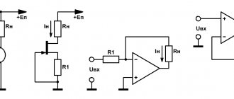
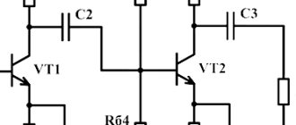
The thermal relay (Fig. 1) is based on a Schmitt trigger.
A thermistor (a resistor whose resistance depends on temperature) is used as a temperature sensor. Potentiometer R1 sets the initial bias on thermistor R2 and potentiometer R3. By adjusting it, the actuator (relay K1) is activated when the resistance of the thermistor changes.
Rice. 1. Scheme of a simple thermal relay using transistors.
Not only a relay, but also a low-current incandescent lamp can be used as a load in this and other circuits in this chapter.
You can turn on an LED with a series current-limiting resistor of 330...620 Ohms, a sound generator, an electronic siren, etc.
When using a relay, the contacts of the latter can include any load electrically isolated from the sensor circuit: a heating element or, conversely, a fan.
To protect the output transistor from voltage pulses that occur when switching the relay winding (inductive load), it is necessary to connect a semiconductor diode in parallel with the relay winding.
So, in Fig. 1 anode of the diode must be connected to the bottom terminal of the relay winding according to the diagram, the cathode - to the power bus. Instead of a diode, a zener diode or capacitor can be connected with the same result.
Purpose and scope of intermediate relays
It is difficult to list the industries in which intermediate relays are used. In all industries, devices for household use, especially in elements of systems with electronic and electrical equipment, an intermediate relay can be installed.
There are several cases where auxiliary relays are used in complex electrical systems:
- For switching sections in various networks independent from each other;
- To increase the response delay of protective elements in circuits with high load currents;
- In secondary circuits, to control the parameters and operating modes of individual elements in high voltage circuits;
One relay on a production line can perform several switching operations simultaneously or sequentially in power or control circuits. In heating and water supply systems, when the deep-well pump is turned on, power is supplied to the relay coil, and when the group of contacts is closed, the control system for the operation of the pump is turned on. The operator’s display displays the main parameters: the presence of voltage on the pump, load currents in each phase, temperature and others, depending on the complexity of the circuit, as necessary.
The other pair will simultaneously close the power supply contacts to the coil of the magnetic starter, when triggered, the current will flow to all three phases of the pump motor. If the starter is assembled using a reversible circuit, another group simultaneously turns off the reversible circuit, eliminating a short circuit.
In a heating system, a signal with weak currents is not capable of turning on the coils of powerful magnetic starters or relays. Therefore, the intermediate relay acts as an amplifier of the control signal; the signal from the heat sensor turns on the intermediate relay, the contacts of which supply voltage to the windings of the magnetic starter, the contacts of which close and power is supplied to heating elements, boilers or other powerful heating devices.
Post navigation
We turn on the headlights or low beam, the DRLs go out
Now let's briefly go over the rules for the operation and use of DRLs: DRLs should be used only during daylight hours; It is prohibited to use DRLs in conjunction with side lights, low and high beam headlights, as well as fog lights. Separately, I would like to dwell on an important point, it concerns the use of DRLs in conjunction with high beam headlights. These are ordinary relays from a set of alarms and other additional equipment. Diagram of a relay containing a diode and connecting its winding: When voltage is applied to the control contacts, the relay is activated and closes or opens the electrical circuit with power contacts. Typical relay circuits. Power contacts are always marked as 30, 87 and 87a
Connecting and installing an LED driver is a waste of time, because the DRLs on LEDs shine regularly for months without any stabilization... However, this statement is easy to dispute. Let's consider connecting fog lights. With the ignition, in this case, the fog lights cannot be turned on without the engine running, usually the plus from the ignition switch or IGN2 is used, which is best looked for using a voltmeter, since if you use a lamp probe, there is a possibility of damage to the car's electronics. Depending on whether there is voltage on them or not, contacts 87 or 87A close; Pin 30 - power supply contact of the relay
Power contacts are always marked as 30, 87 and 87a. Connecting and installing an LED driver is a waste of time, because the DRLs on LEDs shine regularly for months without any stabilization... However, this statement is easy to dispute. Let's consider connecting fog lights. With the ignition, in this case, the fog lights cannot be turned on without the engine running, usually the plus from the ignition switch or IGN2 is used, which is best looked for using a voltmeter, since if you use a lamp probe, there is a possibility of damage to the car's electronics. Depending on whether there is voltage on them or not, contacts 87 or 87A close; Contact 30 is the power supply contact of the relay.
That is, if you turn the key in the ignition but do not start the car, the DRLs will light up. One of the contacts, 87a or 87, may be missing.
Operating principle of the contactor
The operating algorithm of this type of relay involves the use of electrodynamic forces created in a ferromagnet during the passage of electricity through the spiral of turns of the insulated wire of the coil.
Based on the technical features of the switch and the number of contact connections placed in it, the anchor either closes or opens them
The initial location of the L-shaped plate (anchor) is fixed by a spring. By supplying current to the magnet, the armature, with the commutating contact located on it, overcomes the spring forces and is drawn towards the magnetized field.
When moving, the shank located on the contact plane catches the lower contact circuit, moving it down. If the supply of electricity to the coil stops, the spring pulls the yoke back and the device returns to its original form.
Let's look at an example of how an electromagnetic-type relay works in a car.
If it is connected to a three-phase asynchronous motor, the following actions will be reproduced:
- Start – activation of the alarm.
- Starter activation.
- The closing of the last pair of contacts results in the start of the engine mechanism.
In addition, it is the relay that is responsible for turning off the engine when the reverse breaks. This eliminates the problem of sudden engine stops.
To recognize the type of electromagnetic contactor in production, marking values are used, consisting of a set of letters and numbers printed on the device
It is also important to know that an electromagnetic relay can be equipped with several groups of control contacts. The number of the latter depends entirely on the purpose of the specific model of the device.