A double-throw (double-pole) switch is also an electrical switching device, just like a regular (single-pole) switch. But if the latter only allows you to break or connect an electrical circuit, then the switches can operate with several connections. The figure below clearly shows their main differences.
Schematic representation of various switching devices
The picture shows:
- a regular switch and its connection option;
- example of using a double switch;
- connecting a two-pole switch;
- switch.
Note that switches can be in two or more directions, for example, four-pole or three-phase power. It makes sense to talk about the latter in more detail.
Two-way switches: single-pole, double-pole, single-gang
A double-throw (double-pole) switch is also an electrical switching device, just like a regular (single-pole) switch.
But if the latter only allows you to break or connect an electrical circuit, then the switches can operate with several connections. The figure below clearly shows their main differences. Schematic representation of various switching devices
The picture shows:
- a regular switch and its connection option;
- example of using a double switch;
- connecting a two-pole switch;
- switch.
Note that switches can be in two or more directions, for example, four-pole or three-phase power. It makes sense to talk about the latter in more detail.
Operating principle and device
Two-position switch ON-OFF
A classic two-way switch or two-position switch belongs to the same category of devices as a regular single-pole device. However, if the latter simply closes and opens the power circuit, turning the load on or off, then the electric switch switches its contact from one load line to another in 2 positions. This is its fundamental difference from other switching elements, which naturally affects the device.
A two-pole device (unlike a single-pole analogue) contains in its design not two, but three groups of switched contacts. One of them, called the central one, is alternately connected to one direction or the other, supplying power to various consumers. A typical example of such a design is an ordinary toggle switch, which in most equipment is only half used - as a switch or switch. If this device uses the second direction, it turns into a changeover type device, disconnecting one load from the supply network and connecting another.
Based on the type of switched voltages, known samples of 2-position switches are divided into single-phase and three-phase models. More complex designs include products designed for several positions at once (they are called multi-position). Double-pole, double-throw switches belong to the same category of devices.
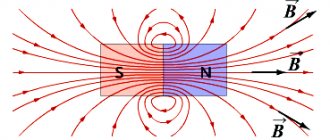
Three-phase switches
Three-phase power switches are widely used in control circuits for powerful asynchronous electric motors; their purpose is to switch the winding from star to delta. This implementation allows you to significantly reduce the starting current. The figure shows a diagram of such a connection.
Switching diagram of electric motor windings
Symbols on the diagram:
- A, B, C – power phases;
- C1, C2, C3, C4, C5, C6 – outputs of the electric motor windings;
- SA – three-pole power switch.
The electric motor starts when its windings are connected in a star; when entering normal mode, it switches to a delta.
Multi-position switches of modular type
The cam burst switch is the most common type of these devices, like other switches, it is used to control various types of electrical loads.
Cam switches
The scope of application of cam switches is quite extensive; here are some examples of their use:
- AC and DC control switchboards;
- emergency shutdown systems, automatic transfer of reserve, switching of operating modes of electric motors;
- control of transformer substations and lighting;
- equipment for substations (control of grounding switches, sectional switches, disconnectors, etc.);
- switching heating equipment modes (turning on, off, switching electric heating elements of the load);
- selection of operating mode of electric welding equipment, etc.
Cam switches consist of several packages (each responsible for switching one line) placed in one housing. The figure below shows the structure of such a package.
Cam Switch Package
Designations in the figure:
- a - fixed contacts (4 pcs.), to which wires are connected;
- b – a special protrusion “cam”, which allows you to hold and move the rod;
- c – group of movable contacts (there are two of them in this type);
- d – two guide grooves (allow the rod to make translational movements);
- e – two rods covered with an insulating shell;
- f – contacts (8 pcs.), usually made of an alloy containing silver;
- g – package;
- h – two threaded rods (fix the bag and the lid);
- I – rotor;
- J – four springs (return the rod to the closed position);
- k - shaft connecting the handle to the rotor;
- l – four screws for clamping cable wires.
Note that the batch switch (cam switch) can have several positions, including zero, that is, when the contacts are disconnected. The figure shows the state of the switch in the neutral position.
Schematic representation of the switch in the zero position
ABB switch in zero position mode
Note that all the main characteristics of the switches are indicated on the device case; the following are displayed there:
- switch type;
- rated current for which the switch is designed;
- switching diagram and table;
- protection class.
Below is a diagram and switching table shown on the housing of the SPAMEL rotation direction switch.
Scheme and switching table of the SPAMEL switch
Thanks to this table, you can clearly see in what position and which groups of contacts are connected.
Household use
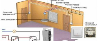
Switches are not used as often in everyday life as light switches, but, nevertheless, there are tasks in which it is impossible to do without them. For example, when it is necessary to control lighting from different places. Switches can be installed at the entrance to the room and near the bed (so as not to get up to turn off the light) or at different ends of a long corridor.
The implementation of such a control scheme is quite simple; its image is shown in the figure below.
Scheme for switching on lighting from two different places
Designations in the figure:
- A, B – switches;
- L – lighting device.
If it is necessary to control lighting from more places, the circuit can be slightly complicated by adding an intermediate switch.
Lighting control from three different locations
Designations in the figure:
- A, B – two-position switches;
- C – intermediate double switch of two directions;
- L1 – lighting device.
Note that using this diagram as a basis, you can control lighting from three or more places. To do this, it is enough to add the required number of intermediate switches to it; they are connected in the same way as device “C” in the diagram presented above.
How to connect
Let's give an example of implementing a lighting control scheme from two places using Legrand switches. This manufacturer produces reliable household models of the Cariva and Valena series, the price of which is not much different from the cost of conventional switches.
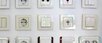
Before you buy switches, pay attention to the various designs; they can be for both hidden and open wiring, as well as with backlighting and position indication on the box (case).
We remind you that all work related to connecting electrical equipment must be performed only when the electrical circuits are completely de-energized. Therefore, before proceeding, make sure that the electricity is turned off; it is advisable to use a special device (probe) for this.
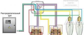
A schematic implementation of the task is shown in the figure below.
Schematic illustration of a dual lighting control installation
The neutral wire is blue, the phase is red. Note that all switching must be performed with the phase.
How a single-key switch is connected can be seen in the bottom figure.
Installation diagram of two Legrand single-key switches
Connecting switches for management from three places is as follows.
Connection to control lighting from three different locations
As you can see, it’s not difficult to connect a one-key or two-key two-way switch, and it will help make lighting control in your apartment more comfortable.
Connection diagrams
If you need to control the inclusion of light from two points, a circuit of two switches in two directions is used. Here is a visual diagram, the figure shows the connections in the junction box.
To control the light from three or more points, two regular switches (two directions) and one or more cross switches are used. The number of cross switches depends on the number of control points: when switching with three switches, one cross switch is used, then you can increase the number of cross switches as many times as you like.
Here is a control diagram for three switches with all connections in the junction box.
For convenience, the diagram shows the colors of the conductors, with the exception of four wires for the cross switch. You will have to pull two two-core cables or another multi-core cable onto it.
The connection diagram for four switches is identical to the previous one, only there is one more cross switch. You can connect as many switches as you like in this way, the only question is practicality.
Connection options
Just as pass-through switches cannot be used individually, but are connected only in pairs, so changeover switches are used only with two pass-through switches. In this case, up to 10 cross switches can be used, and they will always be located between the pass-through switches.
In the diagram, the phase conductor is indicated in red, the neutral conductor in blue. A 1 - basic connection diagram; A 2 is another version of the connection diagram; B1 - wiring method, in which each element of the circuit is connected through a distribution box; B 2 - connection method using an old small junction box and a socket from under a dismantled conventional switch
There can be many options for circuits used for connection: installation is carried out through a distribution box or past it, several lighting groups are connected.
They will improve the system by installing centralized control.
The cross-type changeover switch device is always designed for one lighting group. If it is necessary to connect two groups of lamps, use either two switches or make up one of two separate blocks
Installation via distribution box
This is a traditional connection method, which has both disadvantages and advantages. The advantages include the ability to quickly detect damaged sections of wires in case of problems in the circuit.
In addition, this method involves the traditional laying of wires, which helps during subsequent repair or installation work to determine where the wires are laid and maintain the integrity of the electrical network.
Connection diagram for pass-through and cross switches in a lighting control system from several places. L - phase conductor; N - zero
When installing electrical wiring from the junction box to the pass-through switches, three-core wires are laid. A two-core wire leads from the crossover switch to the feedthroughs.
The sequence of actions when connecting a circuit in which the wires pass through a junction box is as follows:
- A two-core phase wire from the electrical panel is inserted into the box. The neutral conductor of the supply cable is immediately connected to the neutral conductor of the lamp, and the phase conductor is connected to the common conductor of the first pass-through switch No. 1, to input terminal 1 (see figure above).
- The remaining two conductors of the three-core wire are connected to output terminals 3 and 4, which in the junction box will be connected to the two conductors of changeover switch No. 2.
- Install the middle changeover switch. The correct connection of the crossover switch conductors is indicated in the diagram drawn on the device itself.
The second pass-through switch is connected in the same way as the first, but the common conductor is routed through the junction box to the lamp.
Laying an electrical network for organizing lighting using distribution boxes is good because in the event of a malfunction it is easier to identify the damaged section of the electrical wire
If the connection in the junction box was made by twisting, all exposed areas are carefully insulated to prevent a short circuit.
This is done using electrical tape or heat-shrink tubing, which can serve as a marking for the conductors.
We also recommend reading our other material, where we talked in detail about installing a junction box. Read on for more details.
A professional connection is immediately visible - all wires are laid compactly and neatly in the junction box
Direct connection method
Connections are the weak link in any electrical network - this is where oxidation occurs. Regardless of whether it is side clamps or spring-type quick-release terminal blocks, they burn out first; the wire itself remains intact, since it is protected from burnout by a machine.
To minimize the number of connections, the connection is made without a junction box.
They also come to this connection method because users do not always want to see several junction boxes on their wall - these are additional elements that have to be hidden from view
How to install an electrical system without a junction box:
- A cable with two conductors is pulled from the electrical panel - phase and neutral. The latter leads directly to the lamp.
- The phase is connected to the input terminal of the pass-through switch. Two phase wires lead from the two output terminals to the cross wire.
- Two phase conductors are laid from the output contacts of the reversing switch and connected to the second pass-through.
- The common conductor from the second pass-through switching device leads to the lamp and closes the electrical network.
All wires must be marked during electrical installation work. Otherwise, next time, when carrying out electrical installation work, it will be difficult to identify their nature.
It will be quite difficult to fit all the conductors that are connected to each other in the socket box. Therefore, flatter and more compact terminals are used. You can also solve the placement problem by using large socket boxes - with a depth of 60 mm
You can hide distribution boxes in other ways. For example, by installing a box behind a suspended ceiling.
This option cannot be called a win-win, since in complex cases of breakdowns, the detection of a fault may not be limited to one box, and then you will have to remove the ceilings in more than one room.
Distribution boxes are also installed behind the suspended ceiling. In this case, they are all concentrated in one place, and access is provided by an inspection hatch
Check the correct connection like this: every time you press the key of any switch, including the cross switch, the state of the lighting should change - the light should turn off and on. Problems can arise if errors are made during the connection - the circuit is assembled incorrectly, the contacts are mixed up.
The cause of improper operation of the changeover switch can be eliminated only by thoroughly checking the connection directly at the installation site.
Light control remotely and from a switch
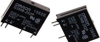
This solution will be acceptable when you need to control from several points, and the wiring has already been laid to one switch. To implement it, you will need a radio relay in the form of a wall switch, such a device is called a “switch-receiver”. More details about this scheme and about radio control of light in general can be found in the publication “Remote control of light via radio channel - a review of solutions”
Using an impulse relay
The pass-through circuit can also be organized using a pulse relay.
What are the benefits?
The main advantage of this scheme is the unlimited number of control points. Each switch requires only two wires.
What are the disadvantages?
You need an installation location in the panel, and accordingly you will have to run all the wiring there.
push-button type
switches as switches . In general, such a solution is acceptable only with a large number of lighting control locations or for any non-standard tasks.
There are many models of pulse relays and in general the issue requires a separate topic, so the details will not be considered within the framework of this publication.
How to establish centralized lighting control?
The control network from several places has a significant drawback - all the switches involved in it do not have a fixed position. Therefore, it is impossible to determine whether the light in the room is on or not if there is no electricity. Installing a conventional switch in front of the first pass eliminates this problem.
To the already known connection diagram for changeover and pass-through switches, one more element is added - a regular single-key one. Place him in the same room or take him to the front door. When enabled, it will allow the system to operate as normal. When turned off, the circuit will be completely de-energized and, regardless of the position of the switches, the light will not light up.
An even better way to improve centralized control is to use a pulse relay. It has great functionality and allows you to control a separate group of electrical equipment or lighting throughout the house.
Useful little things
And finally, a few useful notes on the topic:
Despite the fact that essentially a line of two conductors runs between all switches, without the need for connection in a junction box, it is not recommended to pull conductors directly. This will make it easier to get confused during subsequent repairs or reconstruction of the electrical wiring. It is much more correct and clearer for an outside electrician (who may have to deal with this wiring) when the cable goes from each switch to a box or several boxes.
The wiring is laid, the connections are made, the voltage is applied, but the repair continues and there are no switches available? If you need light, it is quite possible to use a regular switch as a temporary solution. To do this, you need to connect all the conductors in unused socket boxes into bundles and insulate them, leaving only one socket box. In the required socket box, experimentally or logically find the required two wires and attach a regular switch to them.
This concludes the publication about pass-through switches.
How to properly connect a pass-through switch. Scheme of light control from 2 and 3 places.
First of all, before choosing and purchasing, you need to decide what it is - a pass-through switch, what it is needed for, and how it differs from the usual one, two and three-key switches.
A single-key pass-through switch is necessary to control one circuit or lighting line from several points located in different parts of the room or the entire house. That is, with one switch you turn on the lighting when entering a room or corridor, and with another, but at a different point, you turn off the same lighting.
Very often this is used in bedrooms. I went into the bedroom and turned on the light near the door. I lay down on the bed and turned off the light at the headboard or near the bedside table. In two-story mansions, he turned on the light bulb on the first floor, climbed the stairs to the second and turned it off there.
Before assembling such a control scheme, here is what you should pay special attention to:
1 To connect a pass-through light switch, a three-core cable is required - VVGng-Ls 3*1.5 or NYM 3*1.5mm2
2 Do not try to assemble a similar circuit using ordinary switches.
The main difference between regular and pass-through ones is the number of contacts. Simple single-key ones have two terminals for connecting wires (input and output), while pass-through ones have three!
In simple terms, the lighting circuit can be either closed or open, there is no third option.
It is more correct to call a pass-through not a switch, but a switch.
Since it switches the circuit from one working contact to another.
In appearance, from the front they can be absolutely identical. Only the pass key can have an icon of vertical triangles. However, do not confuse them with reversible or crossover ones (more about them below). These triangles point in a horizontal direction.
But from the reverse side you can immediately see the difference:
- the pass-through has 1 terminal on top and 2 on the bottom
- a regular one has 1 on top and 1 on the bottom
Due to this parameter, many people confuse them with two-key ones. However, two-key ones are also not suitable here, although they also have three terminals.
The significant difference is in the operation of the contacts. When one contact is closed, pass-through switches automatically close the other, but two-key switches do not have such a function.
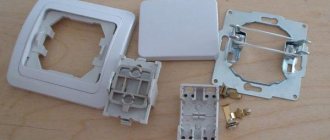
First of all, you need to correctly connect the switch itself in the socket box. Remove the key and the overhead frames.
When disassembled, you can easily see the three contact terminals.
The most important thing is to find the common one. On high-quality products, a diagram should be drawn on the reverse side. If you understand them, you can easily navigate through it.
If you have a budget model, or any electrical circuits are a bit of a mystery to you, then an ordinary Chinese tester in circuit continuity mode, or an indicator screwdriver with a battery, will come to the rescue.
Using the tester's probes, alternately touch all the contacts and look for the one on which the tester will “squeak” or show “0” at any position of the ON or OFF key. It's even easier to do this with an indicator screwdriver.
After you have found the common terminal, you need to connect the phase from the power cable to it. Connect the remaining two wires to the remaining terminals.
Moreover, which one goes where does not make a significant difference. The switch is assembled and secured in the socket box.
Typical connection errors
Ignoring the markings and diagrams printed on the switches leads to connection errors and incorrect operation of the circuit. The most common problem that occurs, especially when installing pass-through switches, is the user incorrectly identifying the location of the incoming contact.
It may be located differently on different devices, so you must read the markings. All the subtleties of choosing pass-through switches are discussed in this material.
If it is not possible to determine the exact location of the incoming terminal, then test the device with a multimeter or an indicator screwdriver
When connecting changeover crossover switches, problems arise if paired wires from pass-through devices are connected to terminals located on the wrong side.
Most often, the device involves a cross connection.
You should always check the circuit before connecting. The input and output contacts of the changeover switch can be located differently
Switch connection diagrams
When designing lighting, you need to know about the basic circuits for connecting switches. The connection diagram of the switch directly depends on the tasks that a particular switch faces, i.e. control of a particular lamp or group of lamps.
1 Connection diagram for a single-key switch:
Connection diagram for two-button switch
The simplest single lamp is connected exactly according to this scheme. The switch contact switches the phase. Most of the lights in our homes and offices are connected in this way.
2 Connection diagram for a two-key switch:
Connection diagram for two-button switch
This circuit is used to turn on (off) lamps in large rooms or single multi-lamp lamps. All lamps or lamps are divided into two groups. Each key serves to control a separate group.
3 Connection diagram for a three-key switch:
Three-key switch connection diagram
The use of this circuit is similar to a two-key switch. All lamps are divided into three groups.
4 Connection diagram for two-way switches:
Connection diagram for two-way switches
In long rooms with two exits, i.e. In walk-through rooms, it is advisable to install walk-through switches - switches for control from two places. These switches have a special contact group and one key. Recently I used such switches in the corridor during the reconstruction of a private house.
Scope of application of changeover devices
Changeover switches are not used so often, but their role in organizing lighting cannot be underestimated. Imagine a situation where there is only one switch installed in a long corridor or at the beginning of a flight of stairs and you have to walk considerable distances in the dark to turn on the light.
Installing a pass-through switch in two directions is quite capable of solving this problem, and a changeover (cross) switch will become indispensable:
- in a three-level apartment - installed near the second floor landing;
- in a large corridor or hall - installed near each door, it will greatly facilitate movement in the dark;
- in the bedroom - you can install one near the door and two near the resting place, and you no longer have to get up to turn off the light.
You can also use a rocker switch to turn on lighting on the street or in the garage, controlling the lamp from the house, gazebo, terrace, etc.
When leaving the room into the corridor at night, the user can turn on the light immediately, rather than moving around in a dark room looking for a switch
Connecting pass-through and cross switches
Introduction
In one of the previous articles, we already examined in detail the connection diagrams for simple one- and two-key switches (for more details, see the article: Connecting a switch), however, such switches have one serious drawback - lighting control, i.e. turning it on and off can only be done from one place. Let's imagine a situation that everyone has encountered, for example: You come home, turn on the light in the hallway, take off your outerwear and go into the room, but wait, the light in the hallway needs to be turned off, and having done this you will have to leave the hallway in the dark, the same goes for long corridors or staircases. In such situations, it becomes necessary to control lighting from two places; it is for solving such problems that the so-called pass-through switches are designed.
In this article we will look at various options for connecting pass-through switches to control lighting from 2, 3 or more places.
NOTE: Before connecting the pass-through switch, you must check the diagram given in its passport and/or the diagram printed on the back of the switch itself (if available).
Lighting control from two places:
To organize lighting control from two places, it is necessary to use 2 pass-through switches. Below are diagrams for connecting two one-key (single) and two two-key (double) pass-through switches.
2.1 Connecting two pass-through single-key switches.
To begin with, let's figure out what a single-key pass-through switch is. Outwardly, it is practically indistinguishable from a conventional single-key switch, but unlike the latter, it has not 2, but 3 terminals for connecting wires, in addition, on the pass-through switch key there may be two triangles located vertically, one above the other and pointing their vertices up and down, respectively:
As you can see in the picture above on the back of the pass-through switch, as a rule, there is a diagram of it, and the terminals for connecting wires to the switch can have various alphabetic, digital or symbolic designations, for example it could be: “L,1,2”; or "1,2,3"; The designations can also be arrows, in which case one arrow points inside the switch, and the other two arrows point out.
Single-key pass-through switches are connected using three-core cables (as shown in the picture above), for example, a VVG 3x1.5 cable - if the internal wiring is made of copper, or an AVVG 3x2.5 cable - if the internal wiring is made of aluminum.
Connection diagram for pass-through switch:
Connecting wires to single-key pass-through switches is carried out as follows:
By connecting 2 pass-through switches in this way, you can organize lighting control from two places. How exactly this scheme works can be seen in the GIF animation below:
As can be seen in this diagram, unlike conventional switches that simply break (turn off) the electrical circuit (see article: connecting a switch), pass-through switches switch from one circuit to another, which is why pass-through switches are often called pass-through switches .
2.2 Connecting two two-key pass-through switches.
A double pass-through switch consists of two single-key pass-through switches combined in one housing; accordingly, such a switch will have 6 terminals for connecting wires, so connecting a pass-through two-key switch must be done with two three-core cables.
Connection diagram for a two-key pass-through switch for 2 points:
Connecting wires to double pass-through switches is carried out as follows:
Types of changeover switches and their markings
The choice of changeover switches has to be made based on a modest list of distinctive characteristics. They are produced by many well-known companies, including Legrand, ABB, Schneider.
Lever electrical equipment is considered more reliable and therefore is often used in factories and public places
Changeover switches are classified:
- According to the method of activation, they are divided into rotary, key and lever types;
- According to the installation method - for devices for internal and external installation.
You won’t find two-key cross-type toggle switches as such on sale. But you can use an Ultra series device from the well-known electrical equipment supplier Schneider Electric by taking two modular-type single-key crossover units and installing them in one housing. If these models are not available, two single-key switches are mounted side by side.
To control two or three groups of lighting fixtures, two or three-key pass-through switches are used, and cross switches, in most cases, are installed separately for each group of lamps
When choosing any electrical device, you must focus on its protection class from external factors - IP.
In most cases, in devices of this type, the IP is quite high and exceeds 40, which allows for use in rooms with traditional high humidity, as well as outdoor location under a canopy.
In rotary changeover switches, the contacts are closed using a special rotary mechanism. They cost a little more than keyboards, but are considered more reliable
In order to correctly connect electrical equipment, it is important to understand the symbols and diagrams printed on the back by the manufacturer.
This is how the diagram indicates a cross-type switch. The same diagram is applied to the device, the arrows show the location of the input and output contacts
If in a conventional switch the marking with the letter L is used to designate the incoming phase terminal, and L1, L2, L3 for the outgoing ones, then in the case of a paired switch the numbers 1, 2, 3, 4 can be used, and the incoming and outgoing terminals are indicated by arrows.
Manufacturers also sometimes put markings on the front side of the switch - for a walk-through switch these are two arrows in the form of a triangle, for a changeover switch - a grid
Next, we will look at the installation features and options for possible connection diagrams using the example of a household cross-type changeover switch complete with adapter switches.