What it is?
In (according to the PUE - permissible continuous current) is the maximum current strength that allows arbitrary operation of an electrical device, not limited in time, that is, not leading to overheating of its current-carrying parts.
When In occurs, two conditions are met:
- the heat release in the conductors and its removal into the surrounding space are balanced;
- the generated heat does not cause damage to the mechanical and chemical properties of the materials necessary for the operation of the device.
When the nominal value is exceeded, an imbalance is observed in favor of heat release: the temperature of the conductive parts increases, followed by melting of the insulation.
This poses a risk of fire and short circuit. Metal elements lose strength and become deformed. All components of the power supply system, from the generator or current source to the consumer, are designed for a certain In during design. This applies not only to devices, but also to wires, connecting elements, etc.
The value of In is indicated in the equipment passport. Also, this parameter, along with other most important ones, is often marked on the body or nameplate of the device. Most preferred: 1; 1.6; 2.5; 4; 6.3 A and multiples thereof.
In addition to the values given in the regulatory document, it is allowed to use:
- for transformers: 15, 30, 60, 75, 120 A and multiples thereof;
- for existing devices (by agreement between the customer and the manufacturer): 1400, 2240 A;
- for converters and transformers for them (also by agreement between the manufacturer and the customer): 37.5, 75 and 150 kA.
The values of In are standardized and specified in GOST 6827-76.
Rated short-circuit breaking capacity (Icu or Icn)
The breaking capacity of a low-voltage circuit breaker is related to the power factor (cos φ) of the faulted section of the circuit. A number of standards provide typical values for this ratio.
The breaking capacity of a circuit breaker is the maximum (expected) current that a given circuit breaker is capable of turning off and remaining operational. The current value mentioned in the standards is the effective value of the periodic component of the fault current, i.e. When calculating this standard value, it is assumed that the aperiodic component of the transient current (which is always present in the worst possible short-circuit case) is zero. This rated value (Icu) for industrial circuit breakers and (Icn) for household circuit breakers is usually specified in kA.
Icu (rated ultimate breaking capacity) and Ics (rated service breaking capacity) are defined in IEC 60947-2 together with the relationship between Ics and Icu for the different utilization categories A (instantaneous breaking) and B (delayed breaking) discussed in subsection Others characteristics of the circuit breaker.
Tests to confirm the rated breaking capabilities of circuit breakers are regulated by standards and include:
- switching cycles consisting of a sequence of operations, i.e. switching on and off during a short circuit;
- phase shift between current and voltage. When the current in the circuit is in phase with the supply voltage (cos φ = 1), cutting the current is easier to achieve than at any other power factor. It is much more difficult to switch off the current at low lagging values of cos φ, with current switching off in a zero power factor circuit being the most difficult case.
Determination principle
In for conductors of wires and cables is determined according to the tables of the “Rules for Electrical Installations”, reference books and other specialized literature, they take into account:
- conductor material (data are mainly indicated for copper and aluminum). Metals and alloys have different resistance, and the balance between heat release (Q = I2 * R, where I is the current strength, R is the electrical resistance of the conductor) and its removal depends on it;
- cross-sectional area of the core: the value of R also depends on this;
- installation method (open or in a channel), number of cores in the cable and insulation material.
To calculate the cross-sectional area of the conductor, measure its diameter D with a caliper, then make a calculation using the formula: S = (3.14 * D2) / 4. Having determined the rated current of the wire, compare it with the rated load current.
If the latter turns out to be larger, take a wire with a larger cross-sectional area of the cores. To determine the rated load current, if it is not indicated on the information plate, you need to know the formulas.
Time-current characteristics (VTC) of circuit breakers
Introduction
As is known, automatic circuit breakers can have the following types of releases that provide protection of the electrical circuit from overcurrents: electromagnetic - protecting the network from short circuits, thermal - providing protection from overload currents and combined, which is a combination of electromagnetic and thermal releases (for more details, read the article “circuit breakers”).
Note: Modern circuit breakers designed to protect electrical networks up to 1000 Volts usually have combined releases.
Circuit breaker releases are actuators that ensure disconnection (disengagement) of an electrical circuit when a current higher than the permissible one occurs in it, and the greater this excess, the faster the disconnection should occur.
The dependence of the tripping time of a circuit breaker on the magnitude of the current passing through it is called the time-current characteristic or abbreviated as VTC .
Conditions and values of VTX
The performance characteristics of the machines are determined by the following values:
1) Instantaneous trip current - the minimum current value that causes automatic operation of the circuit breaker without a deliberate time delay. (GOST R 50345-2010, clause 3.5.17)
Note: operation without a deliberate time delay is ensured by the electromagnetic release of the machine.
The instantaneous tripping current is determined by the so-called “trip characteristic” or, as it is also called, the tripping characteristic.
According to GOST R 50345-2010, there are the following types of circuit breaker response characteristics:
Note: there are also other, non-standard types of characteristics, we talked about them in the article “circuit breakers“.
As can be seen from the table above, the instantaneous tripping current is indicated as a range of values, for example, characteristic “B” assumes that the machine will provide instantaneous tripping when a current flowing through it is 3 - 5 times greater than its rated current, i.e. If a circuit breaker with this characteristic has a current rating of 16 Amps, then it will provide instantaneous tripping at a current of 48 to 80 Amps.
The response characteristics of a circuit breaker can usually be determined by the markings on its body:
2) Conditional non-trip current - a set value of the current that the circuit breaker is capable of conducting without tripping for a given (conditional) time*. (GOST R 50345-2010, clause 3.5.15) According to clause 8.6.2.2 of GOST R 50345-2010, the conditional non-trip current is equal to 1.13 of the rated current of the machine. 3) The verbal trip current is a set current value that causes the circuit breaker to trip within a specified (conditional) time*. (GOST R 50345-2010, clause 3.5.16) According to clause 8.6.2.3 of GOST R 50345-2010, the conditional tripping current is equal to 1.45 of the rated current of the machine.
* The conditional time is 1 hour for switches with a rated current up to 63 A inclusive and 2 hours with a rated current over 63 A. (GOST R 50345-2010, clause 8.6.2.1)
The time-current characteristic of the circuit breaker is determined by the conditions and values given in Table 7 of GOST R 50345-2010 :
Note: The table is valid for machines installed in accordance with the test conditions given below and operating at a temperature of 30 +5 ° C
VTX charts
For convenience, manufacturers in the passports for circuit breakers indicate the time-current characteristics in the form of a graph where the X axis shows the multiple of the electrical circuit current to the rated current of the circuit breaker (I/In), and the Y axis shows the tripping time of the release.
For a detailed consideration, let’s take as an example the VTX graph for a circuit breaker with characteristic “B”
NOTE: All graphs below are provided as an example. Different manufacturers' performance characteristics may differ (see the machine's passport), but in any case they must comply with the requirements of GOST R 50345-2010 and, in particular, the values specified in Table 7 above.
As you can see, the VTX graph is represented by two curves: the first curve (red) is the characteristic of the machine in the so-called “hot” state, i.e. machine is in operation, the second (blue) is the characteristic of the machine in a “cold” state, i.e. machine through which electric current has just begun to flow.
At the same time, the blue curve has an additional dashed line, this line shows the characteristics of the machine (its thermal release) with a rated current of up to 32 Amperes, this difference in the characteristics of machines with ratings up to and above 32 Amperes is due to the fact that in machines with a higher rated current there is a bimetallic plate The thermal release has a larger cross-section and, accordingly, it needs more time to warm up.
Calculation formula
Not all devices, especially household ones, have a rated current value specified.
But the power is usually known. For example, an incandescent light bulb says: 60W, 230 V. The rated current of consumers with active resistance (incandescent lamps, electric kettles, boilers and heaters) is determined from the power calculation formula: W = U * I, hence: I = W / U
For a single-phase network U = 220 V, therefore, the rated current of a 60-watt lamp is: I = 60 / 220 = 0.27 A The rated current of a fuse is calculated similarly - the power is also indicated on its body.
The rated current of a consumer group is calculated taking into account the non-simultaneity coefficient “k”. This approach is due to the fact that the devices never operate simultaneously for an extended period.
For example, if the kitchen has the following electrical appliances:
- stove: 2000 W;
- kettle: 1500 W;
- microwave: 800 W;
- coffee maker: 1000 W.
And the non-simultaneity coefficient is taken equal to k = 0.7 (set for different situations by regulatory documents), then the rated current of the consumer group will be: I = (2000 + 1500 + 800 + 1000) * 0.7 / 220 = 3710 / 220 = 16, 86 A.
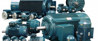
It is somewhat more difficult to determine the rated current of consumers with inductive reactance, the main part of which are transformers (power supplies, stabilizers) and electric motors (refrigerator, vacuum cleaner, etc.).
The total consumed electrical power Wpol is not indicated in the technical documentation for the equipment - only mechanical power on the motor shaft (GOST R 52776-2007, clause 5.5.3.).
To determine Wpol, you should pay attention to two parameters given on the nameplate:
- coefficient of performance (efficiency). A parameter characterizing the amount of friction losses in bearings, magnetization reversal of the magnetic circuit, etc. It is the ratio of the output power Wout (this is what is indicated in the passport) to the active power Wa: n = Wout / Wa;
- cosϕ determines the share of active power Wa in the total power consumption Wpol. In consumers with all kinds of coils (windings of motors, transformers, etc.), part of the power (reactive) is spent on overcoming inductive reactance. The essence of this phenomenon is the occurrence of self-induction emf directed against the current. Since cosϕ = Wa / Wpol, then Wpol = Wa / cosϕ.
Thus, the total power consumption Wpol with a known output power Wout is determined by the formula: Wpol = Wout / (efficiency * cosϕ). Output power Wout is usually measured in the usual watts (W), and total Wpol, to avoid confusion, in volt-amperes (VA).
For example, the nameplate of a refrigerator compressor indicates the following characteristics:
- power: 2 kW;
- Efficiency: 0.85;
- cosϕ: 0.8.
This means that the total power consumption will be: Wpol = 2,000 / (0.85 * 0.8) = 2941 VA. Then the rated current consumed by the refrigerator will be: I = Wpol / 220 = 2941 / 220 = 13.4 A. In the case of a 3-phase motor, In is determined as follows: I = Wpol / (1.73 * U).
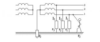
Three-phase power supply system
Wpol is calculated in the same way as for single-phase, voltage U is taken equal to:
- when connected to a 3-phase network: U = 380 V;
- to 1-phase – U = 220 V.
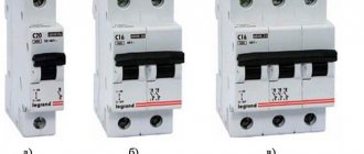
Classes (operation characteristics) of circuit breakers
Trigger classes or characteristics are determined by the spread of the trigger value.
The most used classes are B, C and D. Used in household, lighting and other networks with little or no inrush current. Such machines are installed directly at the consumer’s premises. The electromagnetic release in such devices is triggered when the current exceeds 3 times or more.
It is recommended to install in networks with mixed loads and moderate inrush currents. Also used in household networks, but protect a group of consumers. The most popular machine among electricians. They have a greater overload capacity compared to class B devices. The minimum operating current must exceed the nominal value by 5 or more times.
Devices of this class protect electric motors whose starting current significantly exceeds the rated current. They have a high overload capacity. The minimum operating current is ten rated.
Selection of circuit breakers
Since an increase in current strength above the rated value (overload) entails disruptions in the operation of devices, in this case it is necessary to provide for de-energizing the circuit.
The task is performed by the following protection devices:
- fuses: contain a fusible insert - when overheated, it melts and the circuit opens;
- automatic switches (VA).
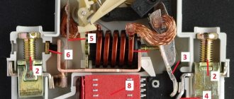
VA consists of two parts:
- thermal release . Bimetallic plate that opens contacts when heated. The response time can be tens of minutes;
- electromagnetic release (coil with solenoid). Triggers almost instantly (0.02 s) when the current reaches a certain value.
The operating threshold of the electromagnetic release for different consumers also requires an individual one. Some fail even with the slightest overload, others can withstand 14 times the excess of In. Therefore, they produce 4 classes of VA, differing in the setting of the electromagnetic device for breaking the circuit (cut-off current setting): A, B, C and D.
The class is selected according to the type of consumers:
- semiconductor elements. Class A, the most sensitive: cut-off current - 2 times higher than the rated current;
- sockets, lighting circuits and others where inrush currents are absent or small. Class B: cut-off current - 3 times higher than the rated current;
input devices for household electrical networks. Class C: cut-off current - 5 times higher than the rated current. Such VAs are not used alone: they ensure the security of the network as a whole, while each group (sockets, lighting) is additionally protected by a class B VA. That is, a class C VA insures class B machines, but in the event of an overload in one of the groups, the entire the network is not de-energized (selectivity);- input devices for networks of buildings and structures, circuits with high starting currents (electric motors act as consumers). Class D: cut-off current - 10 times higher than the rated current. At the entrance to the building, such a VA also plays the role of a selective one - it insures circuit breakers on floors and in individual rooms.
When an overload is less than the cut-off current setting, a current in excess of the rated current flows through the circuit for some time (before the thermal release is activated).
This is taken into account, for example, when choosing an RCD, officially called a “residual current switch”. This is another protective device that de-energizes the circuit when a current leak is detected, thereby preventing electrical injury to the user.
The RCD is selected with a rated current that is one step higher than the corresponding parameter of the VA protecting it.
Rated short-circuit breaking capacity (Icu or Icn)
The breaking capacity of a low-voltage circuit breaker is related to the power factor (cos φ) of the faulted section of the circuit. A number of standards provide typical values for this ratio.
The breaking capacity of a circuit breaker is the maximum (expected) current that a given circuit breaker is capable of turning off and remaining operational. The current value mentioned in the standards is the effective value of the periodic component of the fault current, i.e. When calculating this standard value, it is assumed that the aperiodic component of the transient current (which is always present in the worst possible short-circuit case) is zero. This rated value (Icu) for industrial circuit breakers and (Icn) for household circuit breakers is usually specified in kA.
Icu (rated ultimate breaking capacity) and Ics (rated service breaking capacity) are defined in IEC 60947-2 together with the relationship between Ics and Icu for the different utilization categories A (instantaneous breaking) and B (delayed breaking) discussed in subsection Others characteristics of the circuit breaker.
Tests to confirm the rated breaking capabilities of circuit breakers are regulated by standards and include:
- switching cycles consisting of a sequence of operations, i.e. switching on and off during a short circuit;
- phase shift between current and voltage. When the current in the circuit is in phase with the supply voltage (cos φ = 1), cutting the current is easier to achieve than at any other power factor. It is much more difficult to switch off the current at low lagging values of cos φ, with current switching off in a zero power factor circuit being the most difficult case.
Rated currents of different devices
Here's how much current some devices consume:
- electric stove: power - from 1.2 to 6 kW, cosϕ = Rated current: from 1200 / 220 = 5.45 A to 6000 / 220 = 27.25 A;
- heater : 0.5 - 2 kW, cosϕ = 1. Current - from 2.3 A to 9.2 A;
- vacuum cleaner : 0.5 – 2 kW, cosϕ = 0.9. Current: from 500 / (220 * 0.9) = 2.52 A to 2000 / (220 * 0.9) = 10.1 A;
- iron : 1–2 kW, cosϕ = 1. Current: 4.6–9.2 A;
- hair dryer : 0.6–2 kW, cosϕ = 1. Current: 2.76–9.2 A;
- TV : 0.1–0.4 kW, cosϕ = 1. Current: 0.46–1.84 A.
Why is the red light on the meter blinking?
“Please tell me, the red meter indicator is blinking very often. ... If the indicator blinks frequently, so often that it is simply noticeable, it is most likely that the pulse output of the meter is operating in verification mode. In this case, it is not necessary to send the meter for repair.
Interesting materials:
What does the word naive person mean? What does the word naive mean? What does the word anvil mean? What does the word impose mean? What does the word extraordinary mean? What does the word nyashka mean? What does the word sniff Bebra mean? What does the word knockdown mean? What does the word charming person mean? What does the word offended mean?