In electromechanics, there are many drives that operate with constant loads without changing the rotation speed. They are used in industrial and household equipment such as fans, compressors and others. If the nominal characteristics are unknown, then the electric motor power formula is used for calculations. Parameter calculations are especially relevant for new and little-known drives. Calculation is performed using special coefficients, as well as based on accumulated experience in working with similar mechanisms. The data is necessary for the correct operation of electrical installations.
What is an electric motor?
An electric motor is a device that converts electrical energy into mechanical energy. The operation of most units depends on the interaction of the magnetic field with the rotor winding, which is expressed in its rotation. They operate from DC or AC power sources. The power supply can be a battery, an inverter or a power outlet. In some cases, the engine works in reverse, that is, it converts mechanical energy into electrical energy. Such installations are widely used in power plants powered by air or water flow.
Electric motors are classified by type of power source, internal design, application and power. Also, AC drives may have special brushes. They operate on single-phase, two-phase or three-phase voltage and are air or liquid cooled. AC motor power formula
P = U x I,
where P is power, U is voltage, I is current.
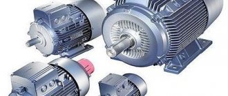
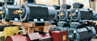
General purpose drives with their own sizes and characteristics are used in industry. The largest engines with a power of more than 100 Megawatts are used in the power plants of ships, compressor and pumping stations. Smaller sizes are used in household appliances, such as a vacuum cleaner or fan.
What types of regulators are there?
There are two types of regulators available on the market today:
- on a variable resistor,
- electronic (stepping and moving).
They all have different ways of controlling the rotation speed and, therefore, the efficiency (electricity consumption) of each type is different. From this point of view, the classic regulator is the cheapest, but ineffective. Let's look at all three types.
Variable resistor regulator
In fact, this rheostat has a huge coil inside. By choosing low speed settings, we are essentially choosing higher circuit resistance. This results in lower current consumption (since the voltage is a fixed value). The devices are bulky in size and inexpensive in price.
Electronic regulator
Electronic are the newest types of regulators available on the market. They are much smaller in size than others. To reduce the voltage, they use capacitors instead of resistors, which, by adjusting the rotation speed, control the power signal. Unlike rheostats, they do not heat up and, therefore, save electricity when the motor operates at low speeds.
Regulators can save up to 40% at “1st” speed and about 30% at “2nd” speed compared to their resistor counterparts. There are electronic types of regulators:
- movable with smooth adjustment.
- step-by-step with a numbered action speed (usually from 1 to 5).
These devices provide a low level of motor movement distortion and, therefore, heat less. An option with the best technology and energy savings.
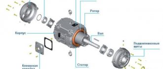
Electric motor design
Drive includes:
- Rotor.
- Stator.
- Bearings.
- Air gap.
- Winding.
- Switch.
The rotor is the only moving part of the drive that rotates around its axis. The current passing through the conductors forms an inductive disturbance in the winding. The generated magnetic field interacts with the permanent magnets of the stator, which causes the shaft to move. They are calculated using the formula for electric motor power by current, for which the efficiency and power factor are taken, including all the dynamic characteristics of the shaft.
Bearings are located on the rotor shaft and contribute to its rotation around its axis. The outer part is attached to the engine housing. The shaft passes through them and comes out. Since the load extends beyond the working area of the bearings, it is called overhanging.
The stator is a stationary element of the electromagnetic circuit of the engine. May include winding or permanent magnets. The stator core is made of thin metal plates called the armature package. It is designed to reduce energy loss, which often occurs with solid rods.
Air gap is the distance between the rotor and stator. A short gap is effective, as it affects the low efficiency of the electric motor. The magnetizing current increases with increasing gap size. Therefore, they always try to make it minimal, but to reasonable limits. Too small a distance leads to friction and weakening of the fixing elements.
The winding consists of copper wire assembled into one coil. Typically laid around a soft magnetized core consisting of several layers of metal. The induction field is disturbed when current passes through the wires of the winding. At this point, the installation enters configuration mode with explicit and implicit poles. In the first case, the magnetic field of the installation is created by a winding around the pole piece. In the second case, the slots of the rotor pole piece are dispersed in the distributed field. A shaded pole motor has a winding that inhibits magnetic disturbance.
The switch is used to switch the input voltage. It consists of slip rings located on the shaft and isolated from each other. The armature current is supplied to the contact brushes of the rotary commutator, which causes a change in polarity and causes the rotor to rotate from pole to pole. If there is no voltage, the motor stops turning. Modern installations are equipped with additional electronic means that control the rotation process.
Engine power and heating
The rated power is usually specified for an ambient temperature of 40°C and is limited by the maximum heating temperature. Since the weakest point in a motor in terms of overheating is insulation, power is limited by the insulation class of the stator winding. For example, for the most common insulation class F, the permissible heating is 155°C at an ambient temperature of 40°C.
The documentation for electric motors provides data that shows that the rated power of the motor drops as the ambient temperature rises. On the other hand, with proper cooling, engines can operate at higher than rated power for a long time.
We have looked at the power consumption and output, but it should be said that the actual operating power consumption P
(motor shaft power at a given moment) should always be less than rated:
R 2 1
This is necessary to prevent engine overheating and to have an overload reserve. Short-term overloads are permissible, but they are limited primarily by engine heating. It is also advisable to install motor overload protection not based on the rated current (which is directly proportional to power), but based on the actual operating current.
Modern manufacturers mainly produce engines from a number of ratings: 1.5, 2.2, 5.5, 7.5, 11, 15, 18.5, 22 kW, etc.
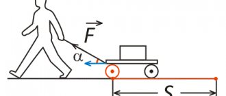
Operating principle
According to Archimedes' law, the current in a conductor creates a magnetic field in which the force F1 acts. If a metal frame is made from this conductor and placed in a field at an angle of 90°, then the edges will experience forces directed in the opposite direction relative to each other. They create a torque about the axis, which begins to rotate it. The armature coils provide constant torsion. The field is created by electric or permanent magnets. The first option is made in the form of a coil winding on a steel core. Thus, the frame current generates an induction field in the electromagnet winding, which generates an electromotive force.
Let us consider in more detail the operation of asynchronous motors using the example of installations with a wound rotor. Such machines operate on alternating current with an armature rotation frequency that is not equal to the pulsation of the magnetic field. That's why they are also called induction. The rotor is driven by the interaction of electric current in coils with a magnetic field.
When there is no voltage in the auxiliary winding, the device is at rest. As soon as an electric current appears at the stator contacts, a constant magnetic field with pulsation +F and -F is formed. It can be represented as the following formula:
npr = nrev = f1 × 60 ÷ p = n1
Where:
npr is the number of revolutions that the magnetic field makes in the forward direction, rpm;
nrev — number of field revolutions in the opposite direction, rpm;
f1—electric current pulsation frequency, Hz;
p—number of poles;
n1 is the total number of revolutions per minute.
Experiencing pulsations of the magnetic field, the rotor receives initial movement. Due to the heterogeneity of the impact of the flow, it will develop a torque. According to the law of induction, an electromotive force is generated in a short-circuited winding, which generates a current. Its frequency is proportional to the rotor slip. Due to the interaction of electric current with a magnetic field, shaft torque is created.
To calculate performance, there are three formulas for the power of an asynchronous electric motor. By phase shift they use
S = P ÷ cos (alpha), where:
S is the total power, measured in Volt-Amps.
P is active power, indicated in Watts.
alpha - phase shift.
By total power we mean the real indicator, and by active - the calculated one.
Pump Load and Motor Load Types
The following types of loads are distinguished:
Constant power
The term "constant power" is used for certain types of loads that require less torque as the rotation speed increases, and vice versa. Constant power loads are typically used in metalworking applications such as drilling, rolling, etc.
Constant torque
As the name implies - “constant torque” - it is implied that the amount of torque required to operate a mechanism is constant, regardless of the speed of rotation. An example of such an operating mode is conveyors.
Variable torque and power
“Variable torque” is the category that is of greatest interest to us. This torque is relevant for loads that require low torque at low speed and require higher torque as the speed increases. A typical example is centrifugal pumps.
The rest of this section will focus solely on variable torque and power.
Having determined that variable torque is typical for centrifugal pumps, we must analyze and evaluate some of the characteristics of a centrifugal pump. The use of variable speed drives is subject to special laws of physics. In this case, these are similarity laws , which describe the relationship between pressure differences and flow rates.
Firstly, the pump flow is directly proportional to the rotation speed. This means that if the pump runs at 25% higher speed, the flow will increase by 25%.
Secondly, the pump pressure will change in proportion to the square of the change in rotation speed. If the rotation speed increases by 25%, the pressure increases by 56%.
Thirdly, what is especially interesting is that power is proportional to the cube of the change in rotation speed. This means that if the required speed is reduced by 50%, this equates to an 87.5% reduction in power consumption.
In summary, the laws of similarity explain why the use of variable speed drives is more appropriate in applications where variable flow and pressure are required. Grundfos offers a range of electric motors with an integrated frequency converter that regulates the speed to achieve exactly this purpose.
Just like feed, pressure and power, the amount of torque required depends on the rotation speed.
The figure shows a cross-section of a centrifugal pump. The torque requirements for this type of load are almost the opposite of those required for "constant power". For variable torque loads, the torque requirement at low speed is low and the torque requirement at high speed is high. In mathematical terms, torque is proportional to the square of the rotation speed, and power is proportional to the cube of the rotation speed.
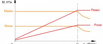
This can be illustrated using the torque/speed characteristic we used earlier when talking about motor torque:
As the motor accelerates from zero to rated speed, the torque can vary significantly. The amount of torque required at a given load also varies with speed. In order for an electric motor to be suitable for a particular load, it is necessary that the torque of the electric motor always exceeds the torque required for a given load.
In the example, the centrifugal pump at rated load has a torque of 70 Nm, which corresponds to 22 kW at a rated speed of 3000 rpm. In this case, the pump requires 20% torque at rated load when starting, i.e. approximately 14 Nm. After starting, the torque drops slightly and then increases to full load as the pump picks up speed.
Obviously, we need a pump that will provide the required flow/pressure (Q/H) values. This means that the electric motor must not be allowed to stop, in addition, the electric motor must constantly accelerate until it reaches its rated speed. Therefore, it is necessary that the torque characteristic matches or exceeds the load characteristic over the entire range from 0% to 100% rotation speed. Any “excess” moment, i.e. The difference between the load curve and the motor curve is used as the rotation acceleration.
Types of electric motors
Based on the power source, drives are divided into those powered by:
- Direct current.
- Alternating current.
According to the principle of operation, they, in turn, are divided into:
- Collector.
- Valve.
- Asynchronous.
- Synchronous.
Valve motors are not classified as a separate class, since their design is a variation of a commutator drive. Their design includes an electronic converter and a rotor position sensor. They are usually integrated together with a control board. Due to them, coordinated commutation of the armature occurs.
Synchronous and asynchronous motors operate exclusively on alternating current. The speed is controlled using sophisticated electronics. Asynchronous are divided into:
- Three-phase.
- Two-phase.
- Single-phase.
Theoretical formula for the power of a three-phase electric motor when connected in a star or delta
P = 3 * Uph * Iph * cos(alpha).
However, for linear values of voltage and current it looks like
P = 1.73 × Uph × Iph × cos(alpha).
This will be a real indicator of how much power the engine takes from the network.
Synchronous are divided into:
- Stepper.
- Hybrid.
- Inductor.
- Hysteretic.
- Reactive.
Stepper motors have permanent magnets in their design, so they are not classified as a separate category. The operation of the mechanisms is controlled using frequency converters. There are also universal motors that operate on direct and alternating current.
Calculation of the power of a 3-phase asynchronous unit
To calculate the net power on the stator winding of an asynchronous 3-phase motor, you should multiply the phase voltage by the phase current and by the power factor, and multiply the resulting power value by three (by the number of phases):
- Pstator = 3 * Uph * Iph * cosφ.
Electric power calculation engine, which is active in nature, that is, the power that is removed from the engine shaft is produced as follows:
- Poutput = Pstator – Ploss.
The following losses occur in an asynchronous motor:
- electrical in the stator winding;
- in the steel of the stator core;
- electrical in the rotor winding;
- mechanical;
- additional.
To calculate the power of a three-phase motor in the stator winding, which is reactive in nature, it is necessary to add up three components of this type of power, namely:
- reactive power consumed to create stator winding leakage flux;
- reactive power consumed to create leakage flux in the rotor winding;
- reactive power consumed to create the main flow.
Reactive power in an asynchronous motor is mainly spent on creating an alternating electromagnetic field, but part of the power is spent on creating leakage fluxes. Leakage fluxes weaken the main magnetic flux and reduce the efficiency of the asynchronous unit.
General characteristics of engines
All motors have common parameters that are used in the formula for determining the power of an electric motor. Based on them, the properties of the machine can be calculated. In different literature they may be called differently, but they mean the same thing. The list of such parameters includes:
- Torque.
- Engine power.
- Efficiency.
- Nominal speed.
- Rotor moment of inertia.
- Design voltage.
- Electrical time constant.
The above parameters are necessary, first of all, to determine the efficiency of electrical installations operating due to the mechanical force of motors. Calculated values give only an approximate idea of the actual characteristics of the product. However, these indicators often use electric motor power in the formula. It is this that determines the performance of the machines.
Asynchronous motor
An asynchronous unit is a device whose peculiarity is that the rotational speed of the magnetic field created by its stator is always greater than the rotational speed of its rotor.
The operating principle of an asynchronous machine is similar to the operating principle of a transformer. The laws of electromagnetic induction are applied (the time-varying flux linkage of the winding induces an EMF in it) and Ampere (an electromagnetic force acts on a conductor of a certain length through which a current flows in a field with a certain induction value).
An asynchronous motor generally consists of a stator, rotor, shaft and support. The stator includes the following main components: winding, core, housing. The rotor consists of a core and a winding.
The main task of an asynchronous motor is to convert electrical energy, which is supplied to the stator winding, into mechanical energy, which can be removed from the rotating shaft.
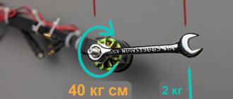
Torque
This term has several synonyms: torque, motor torque, torque, torque. All of them are used to denote one indicator, although from the point of view of physics these concepts are not always identical.
In order to unify terminology, standards have been developed that bring everything to a single system. Therefore, in technical documentation the phrase “torque” is always used. It is a vector physical quantity that is equal to the product of the vector values of force and radius. The radius vector is drawn from the axis of rotation to the point of applied force. From a physics perspective, the difference between torque and torque lies in the point at which the force is applied. In the first case it is an internal effort, in the second it is an external one. The value is measured in newton meters. However, in the electric motor power formula, torque is used as the main value.
It is calculated as
M = F × r, where:
M — torque, Nm;
F is the applied force, H;
r—radius, m.
To calculate the rated torque of the drive, use the formula
Mnom = 30Рnom ÷ pi × nnom, where:
Rnom - rated power of the electric motor, W;
nnom - nominal speed, min-1.
Accordingly, the formula for the rated power of the electric motor should look like this:
Pnom = Mnom * pi*nnom / 30.
Usually all characteristics are indicated in the specification. But it happens that you have to work with completely new installations, information about which is very difficult to find. To calculate the technical parameters of such devices, data from their analogs is taken. Also, only the nominal characteristics that are given in the specification are always known. Real data must be calculated independently.
Number of motor starts per hour
Today's sophisticated motor control systems can control the number of starts per hour for each specific pump and motor. The need to control this parameter is that every time the electric motor is started and then accelerated, a high starting current consumption is noted. The starting current heats the electric motor. If the motor does not cool down, the continuous load from the inrush current will significantly heat the motor stator windings, resulting in motor failure or shortened insulation life.
Typically, the number of starts a motor can make per hour is the responsibility of the motor supplier. For example, Grundfos specifies the maximum number of starts per hour in the technical data for the pump, since the maximum number of starts depends on the moment of inertia of the pump.
Engine power
In a general sense, this parameter is a scalar physical quantity, which is expressed in the rate of consumption or conversion of energy of the system. It shows how much work the mechanism will perform in a certain unit of time. In electrical engineering, the characteristic displays the useful mechanical power on the central shaft. To designate the indicator, use the letter P or W. The main unit of measurement is Watt. The general formula for calculating the power of an electric motor can be presented as:
P = dA ÷ dt, where:
A—mechanical (useful) work (energy), J;
t — time spent, sec.
Mechanical work is also a scalar physical quantity, expressed by the action of a force on an object, and depending on the direction and movement of this object. It is the product of the force vector and the path:
dA = F × ds, where:
s — distance traveled, m.
It expresses the distance that a point of applied force will travel. For rotational movements it is expressed as:
ds = r × d(teta), where:
theta — rotation angle, rad.
In this way, you can calculate the angular frequency of the rotor:
omega = d(teta) ÷ dt.
From this follows the formula for the power of the electric motor on the shaft: P = M × omega.
Power via engine displacement
It is not always possible to determine the engine torque. Sometimes car owners do not even know the meaning of this parameter. In this case, the power of the engine unit can be determined using the engine volume.
To do this, you will need to multiply the volume of the unit by the crankshaft speed, as well as by the average effective pressure. The resulting value must be divided by 120:
- P = (V * n * Peffective)/120 where V – engine volume [cm3], n – crankshaft rotation speed [rpm], Peffective – average effective pressure [MPA], 120 – constant, proportionality coefficient.
This is how the power of a car engine is calculated using the volume of the unit.
Most often, the Peffective value in standard gasoline engines varies from 0.82 MPa to 0.85 MPa, in forced engines - 0.9 MPa, and in diesel units the pressure value ranges from 0.9 MPa to 2.5 MPa.
When using this formula to calculate the actual power of the motor, to convert kW to hp. s., it is necessary to divide the resulting value by a coefficient equal to 0.735.
This calculation method is also far from the most complicated and takes a minimum of time and effort.
Using this method, you can calculate the power of the pump motor.
Nominal speed
Another key indicator of the electromechanical characteristics of the engine is the shaft speed. It is expressed in revolutions per minute. It is often used in the pump motor power formula to find out its performance. But it must be remembered that the indicator is always different for idling and operation under load. The indicator represents a physical quantity equal to the number of full revolutions over a certain period of time.
Calculation formula for speed:
n = 30 × omega ÷ pi, where:
n — engine speed, rpm.
In order to find the power of an electric motor using the shaft speed formula, it is necessary to reduce it to the calculation of angular velocity. Therefore P = M × omega will look like this:
P = M × (2pi × n ÷ 60) = M × (n ÷ 9.55), where
t = 60 seconds.
Introduction
There are at least four common ways to calculate the power of an internal combustion engine. These methods use the following parameters of the propulsion unit:
- Revolutions.
- Volume.
- Torque.
- Effective pressure inside the combustion chamber.
For calculations, you need to know the weight of the car, as well as the acceleration time to 100 km/h.
Each of the following formulas for calculating engine power has some error and cannot give a 100% accurate result. This should always be taken into account when analyzing the data obtained.
If you calculate the power using all the formulas that will be described in the article, you can find out the average value of the actual engine power, and the discrepancy with the actual result will be no more than 10%.
If we do not take into account various scientific subtleties associated with the definition of technical concepts, we can say that power is the energy generated by the motor unit and converted into torque on the shaft. In this case, power is not a constant quantity, and its maximum value is achieved at a certain shaft rotation speed (indicated in the passport data).
In modern internal combustion engines, maximum power is achieved at 5.5-6.6 thousand revolutions per minute. It is observed at the highest average effective pressure in the cylinders. The magnitude of this pressure depends on the following parameters:
- quality of the fuel mixture;
- combustion completeness;
- fuel losses.
Power, as a physical quantity, is measured in Watts, and in the automotive industry it is measured in horsepower. The calculations described in the methods below will give results in kilowatts, then they will need to be converted to horsepower using a special converter calculator.
Design voltage
It is also called nominal. It is a base voltage represented by a standard set of voltages, which are determined by the degree of insulation of electrical equipment and the network. In reality, it may differ at different points of the equipment, but should not exceed the maximum permissible operating conditions designed for the long-term operation of the mechanisms.
For conventional installations, rated voltage refers to the calculated values for which they are provided by the developer in normal operation. The list of standard network voltage is provided in GOST. These parameters are always described in the technical characteristics of the mechanisms. To calculate performance, use the formula for electric motor power by current:
P = U × I.
Power by size
The stator has many different components, one of which is the core. To calculate engine power using dimensions, follow these steps:
- Measure the length and diameter of the core.
- Calculate the constant C, which will be used in further calculations. C = (π * D * n)/(120 * f), where D is the core diameter, n is the shaft rotation speed, f is the voltage frequency (most often this is the industrial frequency of 50 Hz).
- Calculate the power P using the formula P = C * D2 * l * n * 10-6, where C is the calculated constant, D is the diameter of the core, n is the shaft rotation speed, l is the length of the core.
It is better to carry out all measurements and calculations with maximum accuracy so that the calculation of the power of the electric drive motor is as close to reality as possible.
Electrical time constant
Represents the time required for the current level to reach 63% after voltage is applied to the drive windings. The parameter is determined by transient processes of electromechanical characteristics, since they are fleeting due to high active resistance. General formula for calculating the time constant:
te = L ÷ R.
However, the electromechanical time constant tm is always greater than the electromagnetic time constant te. The first parameter is obtained from the equation of the dynamic characteristics of the engine while maintaining the condition when the rotor accelerates from zero speed to maximum idle speed. In this case, the equation takes the form
M = Mst + J × (d(omega) ÷ dt), where
Mst = 0.
From here we get the formula:
M = J × (d(omega) ÷ dt).
In fact, the electromechanical time constant is calculated from the starting torque - MP. A mechanism operating under ideal conditions with linear characteristics will have the formula:
M = Mп × (1 - omega ÷ omega0), where
omega0 — idle speed.
Such calculations are used in the formula for the power of a pump electric motor, when the piston stroke directly depends on the speed of the shaft.
Power via air flow
The power of the unit can also be determined by air flow. True, this calculation method is available only to those car owners who have an on-board computer installed, which allows them to record air consumption at 5.5 thousand revolutions in third gear.
To obtain the approximate engine power, it is necessary to divide the flow rate obtained under the conditions described above by three. The formula looks like this:
- P = G/3, where G is air flow.
This calculation characterizes engine operation under ideal conditions, that is, without taking into account losses on the transmission, third-party consumers and aerodynamic resistance. The actual power is 10 or even 20% lower than calculated.
Accordingly, the amount of air flow is determined in laboratory conditions on a special stand on which the car is installed.
The readings of on-board sensors are highly dependent on their contamination and calibration.
Therefore, calculating engine power based on air flow data is far from the most accurate and efficient, but it is quite suitable for obtaining approximate data.
Basic formulas for calculating engine power
To calculate the actual characteristics of mechanisms, many parameters must always be taken into account. First of all, you need to know what kind of current is supplied to the windings of the electric motor: direct or alternating. The principle of their operation is different, therefore the calculation method is different. If a simplified form of calculating drive power looks like:
Pel = U × I, where
I—current strength, A;
U—voltage, V;
Rel - supplied electrical power. Tue
In the AC motor power formula, phase shift (alpha) must also be taken into account. Accordingly, the calculations for an asynchronous drive look like:
Pel = U × I × cos(alpha).
In addition to active (supplied) power, there is also:
- S - reactive, VA. S = P ÷ cos(alpha).
- Q - full, VA. Q = I × U × sin(alpha).
The calculations also need to take into account heat and induction losses, as well as friction. Therefore, a simplified model formula for a DC motor looks like:
Rel = Pmech + Rtep + Rind + Rtr, where
Рmekh - useful generated power, W;
Rtep—losses for heat generation, VT;
Rind is the cost of charging in the induction coil, W;
RT - losses due to friction, W.
Power through the mass of the car and acceleration time to “hundreds”
Calculation using the weight of the car and its acceleration speed to 100 km/h is one of the simplest methods for calculating the real engine power, because the weight of the car and the stated acceleration time to “hundreds” are the vehicle’s passport parameters.
This method is relevant for engines running on any type of fuel - gasoline, diesel fuel, gas - because it only takes into account the dynamics of acceleration.
When calculating, it is worth taking into account the weight of the vehicle along with the driver. Also, in order to bring the calculation result as close as possible to the actual one, it is worth taking into account the losses spent on braking, slipping, as well as the reaction speed of the gearbox. The type of drive also plays a role. For example, front-wheel drive cars lose about 0.5 seconds at the start, rear-wheel drive cars lose from 0.3 to 0.4 seconds.
All that remains is to find a calculator on the Internet to calculate the power of a car through acceleration speed, enter the necessary data and get an answer. There is no point in presenting the mathematical calculations that the calculator makes because of their complexity.
The result of the calculations will be one of the most accurate, close to the real one.
This method of calculating the real power of a car is considered by many to be the most convenient, because car owners will have to make a minimum of effort - to measure the acceleration speed of up to 100 km/h for the purity of the experiment and enter additional data into an automatic calculator.
Types of asynchronous electric motors according to their design
Depending on the degree of protection, electric motors are divided into:
- Open. They are not very common, because... do not have special devices that prevent the possibility of touching live and rotating mechanisms, as well as the ingress of foreign objects into the unit.
- Protected. They have the above devices.
- Drip-proof. They are equipped with elements that prevent water drops from getting inside (if they fall vertically).
- Closed. The internal cavity is separated by a special shell that does not allow dust to penetrate inside.
- Explosion-proof. They have the highest degree of protection and therefore can be used even in explosive areas.
In addition, electric motors differ in the type of installation: vertical, flanged, integrated, etc.
How are electric motors of various designs designated?
The following notations are commonly used:
- M101 - installed horizontally and fixed on feet welded to the frame or forming a single unit with it.
- M201 is also a horizontal installation, but the engine is suspended on feet placed on top of the frame.
- M301 – flanged motor with horizontal installation; an annular flange with centering sharpening and holes for bolts is located on the bearing shield.
- M302 – the engine is installed vertically (the working end of the shaft is located in the lower part); secured to the bearing shield using a flange.
- M303 - installation type like M302, but the working end of the shaft is located at the top.
- M102 - like M302, but fastening is done on the feet.
- M103 - like M102, but when installed, the working end of the shaft is on top.
- M202 - like M302, but fastening is carried out by a flange on the shield and paws on the frame.
- M203 - like M202, but the end of the working shaft is in the upper part.
Application areas of electric motors
Electric motors are the largest consumers of electricity in the world, accounting for about 45% of all electricity consumed.
- Electric motors are used everywhere, the main areas of application are:
- industry: pumps, fans, compressors, conveyors, driving force for other machines, etc.
- construction: pumps, fans, conveyors, elevators, heating, ventilation and air conditioning systems, etc.
- consumer devices: refrigerators, air conditioners, personal computers and laptops (hard drives, fans), vacuum cleaners, washing machines, mixers, etc.
| ED1 | Functions | Areas of use |
| Rotating electric motors | Pumps | Water supply and wastewater systems |
| Chilled or heated water pumping systems, heating systems, HVAC2, irrigation systems | ||
| Sewage systems | ||
| Pumping of petroleum products | ||
| Fans | Supply and exhaust ventilation, HVAC2, fans | |
| Compressors | Ventilation systems, refrigeration and freezing units, HVAC2 | |
| Accumulation and distribution of compressed air, pneumatic systems | ||
| Gas liquefaction systems, natural gas pumping systems | ||
| Rotate, blend, move | Rolling mill, machines: processing of metal, stone, plastic | |
| Pressing equipment: processing of aluminum, plastics | ||
| Textile processing: weaving, washing, drying | ||
| Mixing, shaking: food, paints, plastics | ||
| Transport | Passenger elevators, escalators, conveyors | |
| Freight elevators, cranes, hoists, conveyors, winches | ||
| Transport means: trains, trams, trolleybuses, cars, electric cars, buses, motorcycles, bicycles, rack railway, cable car | ||
| Angular movements (stepper motors, servo motors) | Valves (open/close) | |
| Servo (position setting) | ||
| Linear motors | Open close | Valves |
| Sorting | Production | |
| Grab and move | Robots |
Note:
- ED - electric motor
- HVAC - heating, ventilation and air conditioning systems