It is very useful for novice radio amateurs to be able to and know how to test a transformer with a multimeter. Such knowledge is useful because it saves time and money.
In most linear power supplies, the lion's share of the cost is the transformer. Therefore, if you happen to have a transformer with unknown parameters in your hands, do not rush to throw it away. Better pick up a multimeter.
Also, for some experiments we will need an incandescent lamp with a socket.
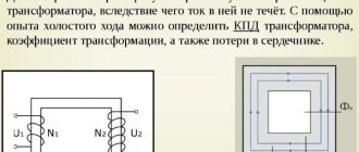
In order to more consciously carry out further experiments and experiments, you should understand how a transformer transformer is designed and works. Let's look at this in a simplified form here.
The simplest transformer consists of two windings wound on a core or magnetic circuit. Each winding consists of conductors isolated from each other.
And the core is made of thin sheets of special electrical steel, insulated from each other.
Voltage is applied to one of the windings, called the primary, and voltage is removed from the second, called the secondary.
When an alternating voltage is applied to the primary winding, since the electrical circuit is closed, a bullet is created in it for the flow of alternating electric current. An alternating magnetic field always forms around a conductor carrying alternating current.
The magnetic field is closed and amplified by the magnetic core and induces an alternating electromotive force of EMF in the secondary winding.
i 2 flows in it .
This knowledge is not yet enough to fully understand how to test a transformer with a multimeter. Therefore, we will consider a number of useful points.
How to find out the power of a transformer
I have been repeatedly asked how to determine the power of a 50Hz transformer that does not have a marking, I will try to tell and show with a couple of examples. In general, there are quite a lot of ways to determine the power of a 50Hz transformer, I will list only a few of them.
1. Labeling.
Sometimes you can find a clear indication of power on the transformer, but this indication may not be noticeable at first glance. The option is, of course, very banal, but you should look for it first.
2. Overall power of the core.
There are tables from which you can find the overall power of certain cores, but since the cores were produced in very different size configurations, and also differed in workmanship, the table may not always be correct. And it is not always possible to find them quickly. However, you can indirectly use tables from the descriptions of unified transformers.
3. Unified transformers.
Even during the union, and indeed after it, a huge number of unified transformers were produced, you can recognize them by the markings starting with TPP, TN, TA. If TA is less common, then TPP and TN are found very often.
Operating modes
A two-winding transformer is capable of operating in one of three modes:
- idle;
- in load mode;
- in a short circuit state.
To carry out calculations of the modes of electrical conductivity circuits, they are replaced by a load, the value of which is equal to the losses when operating in idle mode. Calculations of equivalent circuit parameters are carried out experimentally, transferring the transformer to one of the possible modes: no-load or short-circuit. In this way you can determine:
- level of active power losses during idle operation;
- the magnitude of active power losses in a short-circuited device;
- short circuit voltage;
- no-load current strength;
- active and reactance in a short-circuited transformer.
Idle settings
To switch to idling operation, it is necessary to remove the load on the secondary winding, that is, open the electrical circuit. There is no voltage in an open coil. The main component of the current in the primary circuit is the current arising in the reactances. Using measuring instruments, it is quite easy to find the basic parameters of the alternating magnetizing current, using which you can calculate the power loss by multiplying the current strength by the applied voltage.
The idle measurement diagram is shown in Figure 3. The diagram shows the points for connecting measuring instruments.
Rice. 3. Idle mode diagram
The formula used to calculate the parameters of reactive conductivity looks like this: W = Ix%*Snom / 100* Unom2 The multiplier of 100 in the denominator is used because the value of the no-load current Ix is usually expressed as a percentage.
Short circuit mode
To switch the transformer to operate in short-circuit mode, the low-voltage winding is short-circuited. The second coil is supplied with a voltage such that the rated current circulates in each winding. Since the applied voltage is significantly lower than the rated voltages, the active power losses in conduction are so small that they can be neglected.
Thus, we are left with active powers in the transformer, which are spent on heating the windings: ΔPk = 3* I1nom * Rt . Expressing the current I1 nom through the voltage Uka and resistance Rt, multiplying the expression by 100, we get a formula for calculating the voltage drop in the zones active resistance (in percent):
The active resistance of a two-winding power transformer is calculated using the formula:
Substituting the value of Rt into the previous formula, we get:
Conclusion: in a short-circuited transformer, the voltage drop in the active resistance zone (expressed in %) is directly proportional to the amount of active power loss.
The formula for calculating the voltage drop in the reactance zones is:
From here we find:
The values of reactive resistance in modern transformers are much less than active ones. Therefore, we can assume that the voltage drop in the reactance zone Uk p ≈ Uk, therefore for practical calculations you can use the formula: XT = Uk*Unom2 / 100*Snom
The reasoning given above is also valid for multi-winding, including three-phase transformers. However, calculations are carried out for each winding separately, and the problem comes down to solving systems of equations.
Knowledge of power factors, dissipation resistance and other parameters of magnetic circuits allows you to make calculations to determine the values of rated loads. This, in turn, ensures that the transformer operates within the rated power range.
How to find out the power of a transformer?
Radio electronics for beginners
For the manufacture of transformer power supplies, a single-phase power transformer is required, which reduces the alternating voltage of the 220 volt mains to the required 12-30 volts, which is then rectified by a diode bridge and filtered by an electrolytic capacitor.
These transformations of electric current are necessary since any electronic equipment is assembled on transistors and microcircuits, which usually require a voltage of no more than 5-12 volts.
To assemble a power supply yourself, a novice radio amateur needs to find or purchase a suitable transformer for the future power supply. In exceptional cases, you can make a power transformer yourself. Such recommendations can be found on the pages of old books on radio electronics.
But nowadays it’s easier to find or buy a ready-made transformer and use it to make your own power supply.
Full calculation and independent production of a transformer for a beginning radio amateur is quite a difficult task. But there is another way. You can use a used but serviceable transformer. To power most home-made designs, a low-power power supply with a power of 7-15 watts is enough.
If the transformer is purchased in a store, then, as a rule, there are no special problems with selecting the right transformer. The new product has all its main parameters indicated, such as power , input voltage , output voltage , as well as the number of secondary windings, if there is more than one.
But what if you come across a transformer that has already worked in some device and you want to reuse it to design your own power supply? How to determine the power of a transformer, at least approximately? The power of the transformer is a very important parameter, since the reliability of the power supply or other device you assemble will directly depend on it. As you know, the power consumed by an electronic device depends on the current it consumes and the voltage required for its normal operation. Approximately this power can be determined by multiplying the current consumed by the device ( In) by the supply voltage of the device ( Un ). I think many are familiar with this formula from school.
P=Un * In
,where Un – voltage in volts; Iн – current in amperes; P – power in watts.
Let's look at determining the power of a transformer using a real example. We will train on the TP114-163M transformer. This is an armor-type transformer, which is assembled from stamped W-shaped and straight plates.
is worth noting that transformers of this type are not the best in terms of efficiency . But the good news is that such transformers are widespread, often used in electronics and can be easily found on the shelves of radio stores or in old and faulty radio equipment.
In addition, they are cheaper than toroidal (or, in other words, ring) transformers, which have high efficiency and are used in fairly powerful radio equipment.
So, before us is the transformer TP114-163M. Let's try to roughly determine its power. As a basis for calculations, we will take recommendations from the popular book by V.G. Borisov "Young Radio Amateur".
To determine the power of a transformer, it is necessary to calculate the cross-section of its magnetic core. In relation to the TP114-163M transformer, the magnetic core is a set of stamped W-shaped and straight plates made of electrical steel. So, to determine the cross-section, it is necessary to multiply the thickness of the set of plates (see photo) by the width of the central lobe of the W-shaped plate.
Reactive power losses
Let's remember how an ideal two-winding transformer works (see Fig. 2). When the primary winding is under alternating voltage (for example, from an electrical network), a magnetic flux will arise that penetrates the secondary inductor. Under the influence of magnetic fields, the secondary windings are excited, in the turns of which an EMF arises. When active power is connected to the device, alternating current begins to flow in the secondary circuit at the frequency of the input current.
Rice. 2. Transformer design
In an ideal transformer, a directly proportional connection is formed between the voltages in the windings. Their ratio is determined by the ratio of the number of turns of each coil. If U1 and U2 are the voltages in the first and second windings, respectively, and w1 and w2 are the number of turns of the windings, then the formula is valid: U1 / U2 = w1 / w2 .
In other words: the voltage in the working winding is as many times greater (less) as the number of windings of the second coil is increased (decreased) in relation to the number of turns forming the primary winding.
The quantity w1 / w2 = k is usually called the transformation coefficient. Note that the formula given above also applies to autotransformers.
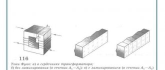
In a real transformer, part of the energy is lost due to magnetic flux leakage (see Fig. 1). The zones where the concentration of scattering fluxes occurs are indicated by dotted lines. The figure shows that the leakage inductance covers the magnetic circuit and extends beyond the windings.
The presence of reactive resistance in combination with the active resistance of the windings leads to heating of the structure. That is, when calculating efficiency, it is necessary to take into account the impedance of the transformer.
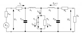
Let us denote the active resistance of the windings by the symbols R1 and R2, respectively, and the reactive resistance by the letters X1 and X2. Then the impedance of the primary winding can be written as: Z1= R1+jX1 . For the working coil, we will accordingly have: Z2= R2+jX2 , where j is a coefficient depending on the type of core.
Reactance can be represented as the difference between inductive and capacitive indicators: X = RL – RC. Considering that RL = ωL , and RC = 1/ωC , where ω is the current frequency, we obtain a formula for calculating reactance: X = ωL – 1/ωC .
Without resorting to a chain of transformations, we present a ready-made formula for calculating the impedance, that is, for determining the impedance of the transformer:
The total resistance of the transformer must be known to determine its efficiency. The magnitude of losses mainly depends on the material of the windings and the design features of the transformer iron. Vortex flows in monolithic steel cores are much greater than in multi-section magnetic core structures. Therefore, in practice, cores are made from thin plates of transformer steel. In order to increase the resistivity of the material, silicon is added to the iron, and the plates themselves are coated with insulating varnish.
To determine the parameters of transformers, it is important to find active and reactance resistance and calculate no-load losses. The above formula is not practical for calculating impedance due to the complexity of measuring inductive and capacitive reactance values. Therefore, in practice, other calculation methods are used, based on the characteristics of the operating modes of power transformers.