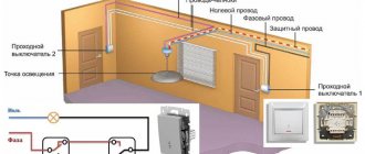
Where to place the switch? This is a difficult question if you need to turn the lights on and off in a large room with several entrances, or in a long corridor. If there is only one switch and there is a lot of space, this is inconvenient.
Is it possible to do better - to turn the lights on and off from different ends of the corridor or staircase in the entrance, in the local area from the house, garage, from the gate, and so on? In our digital age, radio-controlled remote controls, motion sensors, etc. immediately come to mind. This is great, but it can be done simpler, cheaper and more convenient. You just need to use a pass-through switch.
Many of us have come across a circuit of a pass-through switch in a school problem book. The problem for the seventh grade suggests creating a diagram in which you can turn on and off a light bulb at either end of the corridor. To understand the operating principle of a pass-through switch, let’s look at the solution to this simple problem.
First, a simple diagram of “one light bulb and one switch”:
Key K1 is closed, the light is on. If you open the contacts, the lamp will go out. Using such devices, the problem of turning on and off from different ends of the corridor cannot be solved: even if we can turn on the light with different switches, we will not be able to turn it off just as easily.
Pair of pass-through switches
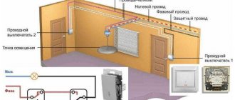
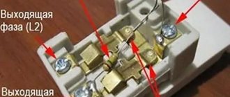
To solve the problem, you need not switches, but switches, and you also need an additional wire. The switch transmits voltage to one of two wires:
Here the phase is transferred from pin 1 to 2. If you click the switch, the voltage from pin 1 will flow to 3.
In any position of the switch, only one of the wires will be energized: 2 or 3.
This is the electrical circuit of a pass-through switch: a simple switch.
But for operation you need at least one more walk-through light switch. You need to run two wires to it from the first switch.
What happens if we click switch 1? The circuit will open. What if there is switch 2? The same.
This means that the light can be turned off from either end of the corridor. And after that, you can turn it on by clicking any of the switches. For example, first:
The single-key pass-through switch does not have On or Off positions. Any switching of one of the pair of switches changes the state of the system: if the light was on, it will go out, and if it was turned off, it will light up.
Connecting to the network
For efficient and optimal operation of the device, you need to correctly select the appropriate three-key switch circuit. In any case, four wires should come out of the wall: one - phase (usually carried out separately) - is “sent” to the distribution box, and the remaining three wires (marked in different colors on the diagram) are connected to groups of light bulbs.
It is important to first turn off the power to the network by unscrewing the plugs or turning off all the machines in the apartment. Also, if unauthorized persons have open access to the panel, it is recommended to warn other residents and neighbors about electrical repair work, and even better, hang a warning sign in a visible place
In more detail, connecting a three-key switch is as follows:
Make sure there is no voltage using an indicator screwdriver. Determine where the phase, neutral and ground are in the incoming wiring (if the markings were followed when laying the network, then blue indicates neutral, green indicates protective, otherwise you will have to turn on the network and determine the phase with an indicator screwdriver). Strip all wires one centimeter. Connect the phase of the supply wire from the distribution box to the common contact of the device (single on top). Connect the neutral of the main wire to the neutral conductors of all lighting groups. Secure the remaining wires in pairs: one wire of the switch with one lamp, the second with the second, the third with the third. Make sure that the screws and terminals fit tightly to the wires, for which you can try to “loose” them. It is advisable to connect the wires with WAGA terminals and perform the usual twisting with insulating tape. Insert the switch core into the socket box. Secure the device with screws or special “claws”. Check the correct connection by checking the diagram. Attach the protective cover
First insert the side keys (it is important not to miss the placed grooves and buttons), and then install the central plate
What to buy to implement the scheme
Understanding how a pass-through switch works, you can independently install a convenient lighting control circuit. Products from several companies are popular on the electrical goods market, for example legrand pass-through switches. They are functional, have an attractive design, some with LED backlighting.
The legrand valena pass-through switch, if it is without a pair, can work as a simple one. But usually they are bought in pairs.
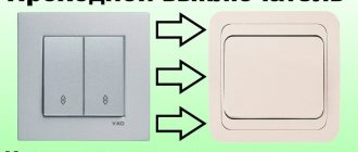
Buyers often ask how a pass-through switch looks different from a regular one. There are few differences: enterprises use a single housing design for different devices. There is no marking on the pass-throughs indicating switching on (sometimes there is one, due to the use of standard components, but they do not pay attention to it). Differences in the connection of electrical contacts can be easily determined by a person familiar with electrical engineering.
The figure shows the connection of a pair of legrand pass-through switches operating for one group of lamps.
Pass-through switches, like regular ones, are available with one or two keys. Two-key controls control two groups of lamps. You can, for example, adjust the brightness of the lighting by turning on and off groups of light bulbs in a chandelier.
No worse than products from other companies: lezard, lexman, abb, schneider electric.
Lezard pass-through switches are connected in the same way as those made by legrand and other companies.
It is very simple to assemble a circuit from devices from any manufacturer, but sometimes difficulties arise because circuits with errors are found on commercial sites on the Internet. Sometimes cheap Chinese devices are accompanied by paper instructions with errors in the circuits.
Use the simplest diagram on which everything is clear and which you understand.
Controlling a lighting fixture from several points
There are several schemes that allow you to install the switch at different points in the room. The simplest diagram involves placing switches on the sides in one line. If you need to organize several places, then you will have to design a complex electrical wiring diagram. However, even a novice master can figure out this process if he wants.
An example of installing a lamp, with control from different points
The main thing here is not to confuse the location of the conductor cores, then there will be no problems with the connection.
If you plan to control a lamp with several light bulbs using a pass-through type switch, then the installation diagram becomes more complicated. After all, then you will have to install multi-key devices with more clamps.
Prices for pass-through switches
Pass-through switch
Turning lights on and off from ten places
We examined in detail the switching scheme for lamps from two different places.
But is it possible to make the light turn on and off from three, four places, and so on? For example, when leaving an apartment, on any floor, turn on the light on the stairs, and when leaving the entrance, turn it off. And do the same in reverse order: turn on the light when entering the entrance, and turn it off at your door. Or late at night, leaving the office into the corridor, where the zealous caretaker has already turned off the light, do not wander in the dark, but flip the switch at your door, let there be light! And then turn it off on the way out. And there should be several such switches in the corridor - at different doors.
To organize such lighting, you need to use more complex pass-through switches, they are called cross switches. Let's consider their functioning.
A crossover switch is something that has two input terminals and two output terminals. A phase comes to one input, an empty wire comes to the other, in random order.
Accordingly, at the outputs we have: on one - phase, on the other - nothing. By clicking the cross switch key, we will reverse the phase and “blank” on the output terminals.
If you place a crossover switch between two pass-through switches, you get three switching points. Each switch, if you change its state, changes the lighting: if the light was on, it will go out, and if it was off, it will turn on.
Look at the picture. At the moment the circuit is closed, but what happens if you click any of the three devices? The circuit between the input and output will open and the light will go out.
Interestingly, after turning off, we can turn on the light, again by clicking ANY switch.
You can put two cross switches, three, four... in the middle of the circuit. no matter how much it’s a pity. And any switch will change the state of the system.
This may seem surprising, especially since a long chain of switches can be difficult to understand. But nevertheless the scheme works! After all, no matter the position of the switching devices, the phase is not “lost” - it comes to one of the two outputs of each cross-switch, and only the last pass-through “selects” the phase or its absence.
Where is the device placed?
As a rule, pass-through switches are installed in different zones to make them convenient to use. It is not necessary to use two switches. So, one of them can become the main one, and the other auxiliary.
If the electrical wiring was located in a corrugated tube, then when installing a pass-through device, it will be possible to perform the replacement without gating the ceilings.
Electrical wiring in a corrugated tube
Most often, standard pass-through switches with one or two keys are placed at the following points:
- On both sides of a narrow corridor. If there is a door in the center, then you can also install the device near it.
- In spacious bedrooms. So, according to the standard, one switch can be installed at a distance of 30-40 centimeters from the door frame, and the other above the bed.
- On the landing.
- Along the path in the courtyard of a private house. After all, it will be convenient to go for a walk in the evening, and if necessary, turn on and off the lights along the way.
- In the halls of a large area, where there are several entrances on the sides.
Using a pass-through switch is advisable not only to save electricity, but is also necessary for the safety of movement. It turns out that the only drawback is the difficulty of installation for some masters.
Clip-on crossover switches are in demand
Pass-through switches are produced in the same housings as conventional ones. There are overhead and built-in models, in versions for internal and external wiring. Surface-mounted models of pass-through and cross switches are in demand because they are used in large quantities when improving lighting systems, including when installing outdoor lighting.
When building your home, a convenient switching system with pass-through switches can be included in the electrical wiring project.
Hidden and outdoor installation methods
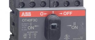
The very first thing you have to decide is what type of switch is needed, which can be indoor or outdoor.
In the first case, installation is carried out inside the wall, for which holes of the appropriate size are cut in it. This type of device is used most often, since the wiring is mainly laid in a hidden way.
External switches are used either in wooden houses, in which the wiring is most often done in an open type, or when lighting devices are laid according to a temporary scheme - in this case, in order not to cut the walls, the wires are laid on their surface.
New technologies: touch pass-through switches
Stylish touch switches are more expensive than regular ones, but they are in demand - they have become a natural part of modern “digital culture”.
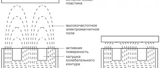
Touch devices are quite complex electronic devices. A high-power thyristor or transistor is used to switch the current, and the signal that opens (or locks) the device comes from a sensor - a sensor that responds to some external influence.
The sensor can be a motion sensor, or an acoustic one, or a capacitive one that responds to touch. Sensitive sensors react even before touching, just bring your hand to a distance of 1-3 centimeters. Homes usually install capacitive touch switches, or those combined with a motion sensor. All touch devices can be controlled remotely. If the control panel is not included, it must be purchased separately.
The semiconductor device responsible for turning the current on and off can also be used to control the current strength and brightness of the light, if equipped with a dimmer. It is important to know that dimmers are not suitable for all lighting fixtures.
Pass-through and cross touch switches, like mechanical ones, are used to control lighting fixtures from different points. Compared to mechanical ones, they are more functional: they can be controlled remotely and control the light intensity.
Externally, touch devices are a smooth glass panel; when connected, there is a visible indication on it: blue firefly - OFF, red - ON. To control the lighting device, you just need to touch the device panel.
The photo shows a touch switch.
The paradox is that technologically advanced sensor devices do an excellent job of controlling incandescent or gas-discharge lamps, but problems arise when turning on advanced LED lamps. In the “touch switch - LED lamp” circuit, when turned off, weak electrical impulses can be induced, due to which the LEDs “wink”. Sometimes there are problems with the dimmer if it regulates the current through the LEDs.
In this case, it is recommended to install an additional adapter... or simple mechanical switches through which no pulses pass.
The figure shows a diagram of connecting the adapter in parallel with the LED lamp.
In this picture, the adapter is connected to the junction box and affects all LEDs included in this circuit.
Let's look at the connection diagrams for pass-through touch switches.
This shows the connection of two touch pass-through switches.
Shown here is the connection of three pass-through touch switches.
Note that in the middle there is the same touch switch as at the edges. That is, touch devices are not divided into “simple” and “cross”.
In the chain of touch switches there is a “main” one - which is shown on the left; three wires go to it (one wire is from the load). Before starting work, the system must be synchronized. Touch the panel of the main device and wait for a beep for 5 seconds. After this, you need to touch the second switch. Synchronization completed. Next, the third, fourth, and so on are synchronized with the main switch.
A device that controls two groups of luminaires
Connection diagram for two-key pass-through switches
It is advisable to install a two-key pass-through switch in a large room where it is necessary to control several lighting fixtures. Its design consists of two single switches in a common housing. Installing one device to control two groups allows you to save on laying cables to each of the single-key switches.
Installation of double pass-through switch
Such a device is used to turn on the light in the bathroom and toilet or in the corridor and on the landing; it is capable of turning on the light bulbs in a chandelier in several groups. To install a pass-through switch designed for two light bulbs, you will need more wires. Six wires are supplied to each, since, unlike a simple two-key switch, the pass-through switch does not have a common terminal. Essentially, these are two independent switches in one housing. The switching circuit for a switch with two keys is performed in the following sequence:
- Socket boxes for devices are installed in the wall. The hole for them is cut with a hammer drill with a crown. Two wires with three cores are connected to them through grooves in the wall (or one six-core wire from the distribution box).
- A three-core cable is supplied to each lighting device: neutral wire, ground and phase.
- In the switching box, the phase wire is connected to two contacts of the first switch. The two devices are connected to each other by four jumpers. Contacts from lamps are connected to the second switch. The second wire of the lighting fixtures is connected to the neutral coming from the distribution board. When switching contacts, the common circuits of the switches are closed and opened in pairs, ensuring that the corresponding lamp is turned on and off.
Cross Switch Connection
Two-key switches are also used when it is necessary to control lighting from three or four places. A double cross-type switch is installed between them. Its connection is provided by 8 wires, 4 for each limit switch. For complex connections with many wires, it is recommended to use junction boxes and label all cables. A standard Ø 60 mm box will not accommodate a large number of wires; you will need to increase the size of the product or install several paired ones or purchase a Ø 100 mm distribution box.
Wires in the junction box
It is important to remember that all work with electrical wiring and installation of devices is carried out with the voltage turned off. This video describes the device, connection principle and installation of pass-through switches:. This video describes the device, connection principle and installation of pass-through switches:
This video describes the device, connection principle and installation of pass-through switches:
https://youtube.com/watch?v=9cG_VmdR4uk
This video shows an experiment in which different methods of connecting wires were tested:
Wiring diagram
The principle of connecting pass-through switches
Connection diagram for a two-button switch with connection through a distribution box
Everything is written correctly in the article, but I came across the fact that the electrician who previously installed the switches did not leave spare wires in the box, and when one aluminum wire broke, he had to tinker with extending this wire. I advise you to leave a reserve for at least two repairs.
I myself studied to become an electrician and sometimes work part-time as an electrician. But every year, or even every month, more and more electrical questions are created. I work on private calls. But your published innovation is new to me. The scheme is interesting and will definitely be useful to me in the near future. I always try to take the advice of “experienced” electricians.
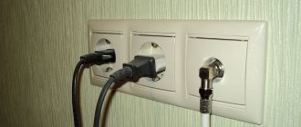
Pass-through socket - it's very simple
Having become familiar with the remarkable properties of walk-through switches, we expect miracles from such an object as a walk-through socket. But there's nothing special here. There is simply an end socket (electrical wires go to it that don’t go anywhere else), and a pass-through socket - it is connected to the wiring, to which several more sockets are connected.
Pass-through sockets have neither design nor circuit features. The name simply reflects their place in the electrical supply system.
What limits the number of pass-through switches
A chain of switches that allows switching electric current from several points should not be too cumbersome. The contacts resist electric current. It is small, but over a long chain of contacts the current can decrease noticeably. With a large number of switches connected one after another, the reliability of the circuit decreases and failures are possible. Therefore, we rarely see a string of pass-through and crossover switches of ten or more pieces. Most often this is a pair of switches, somewhat less often - a chain of three, four, five.
Using these devices makes life more convenient and saves energy.
Types of pass-through switches
So, we looked at different options for this class of devices. In conclusion, we list their types.
By technology:
- mechanical;
- semiconductor (touch, with remote control).
By the number of independent loads:
- single-line;
- multi-line (for 2, 3 groups of lamps).
In addition, mechanical switches come in two types:
- simple checkpoints;
- cross.
Connecting pass-through switches is very simple. Good luck!
Principle of operation
Walk-through switches are no different in appearance from conventional key switches - their design and principle of operation have their own specifics. The main differences between these switching devices are the number and order of connection of the switching contacts.
When operating 2-pass switches, the order of breaking and closing the chain supplying phase voltage to the lighting device is more complex and branched. During the switching process, two such switches, the diagram of which is discussed below, close one of the connecting lines while simultaneously opening the other.
Due to this, it is possible to implement the principle of separate control of the same lighting device from two places located at a considerable distance from one another. The most typical example of such an organization is the location of switches at opposite ends of a long corridor. This feature ultimately determines the specifics of installation of walk-through switches within the boundaries of a particular inhabited room.