Introduction
The modern radio amateur now has access to not only ordinary components with leads, but also such small, dark parts that you can’t understand what’s written on them. They are called "SMD". In Russian this means “surface mount components”. Their main advantage is that they allow the industry to assemble boards using robots that quickly place SMD components in their places on the printed circuit boards, and then mass bake them to produce assembled printed circuit boards. The human share remains with those operations that the robot cannot perform. Not yet.
The use of chip components in amateur radio practice is also possible, even necessary, as it allows you to reduce the weight, size and cost of the finished product. Moreover, you practically won’t have to drill.
Another important quality of surface mount components is that, due to their small size, they introduce fewer parasitics. The fact is that any electronic component, even a simple resistor, has not only active resistance, but also parasitic capacitance and inductance, which can manifest itself in the form of parasitic signals or incorrect operation of the circuit
SMD components are small in size, which helps reduce parasitic capacitance and inductance of the component, therefore improving the performance of the circuit with small signals or at high frequencies.
For those who first encountered SMD components, confusion is natural. How to understand their diversity: where is the resistor, and where is the capacitor or transistor, what sizes do they come in, what types of SMD parts are there? You will find answers to all these questions below. Read it, it will come in handy!
Marking of SMD components
Sometimes it seems to me that the labeling of modern electronic components has turned into a whole science, similar to history or archeology, since in order to figure out which component is installed on the board, sometimes you have to conduct a whole analysis of the elements surrounding it. In this regard, the Soviet output components, on which the denomination and model were written in text, were simply a dream for an amateur, since there was no need to rummage through piles of reference books to figure out what these parts were.
The reason lies in the automation of the assembly process. SMD components are installed by robots, in which special reels are installed (similar to the reels with magnetic tapes) in which chip components are located. The robot doesn’t care what’s in the bag or whether the parts are marked. Humans need labeling.
What is SMD
First of all, what does “SMD” mean and where does this strange name come from? It's very simple: this is an abbreviation for the English expression Surface Mounted Device, meaning a device mounted on a surface.
That is, unlike a conventional radio component, the legs of which are inserted into holes in the printed circuit board and soldered on the other side, the smd device is simply placed on the contact pads provided on the board and soldered on the same side.
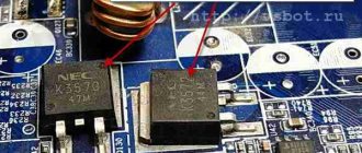
Fragments of boards assembled using SMD technology
Surface mount technology not only made it possible to reduce the dimensions of elements and the density of elements on the board, but also significantly simplified the installation itself, which today is easily handled by robots. The machine places the electronic component at the desired location on the board, heats this location with IR light or a laser to the melting temperature of the solder paste applied to the pads, and the installation of the element is completed.
Marking of year and month of manufacture
In accordance with GOST 25486-82, two letters or a letter and a number are used to indicate the date. The first character corresponds to the year, and the second to the month. This type of coding is used not only for transistors, but also for other domestic semiconductor elements. On foreign instruments, the date is indicated by four digits, the first two of which correspond to the year, and the last - the week number. Let's consider what the code marking of transistors means, corresponding to the date of manufacture. Year of issue/symbol: 1986 – U, 1987 – V, 1988 – W, 1989 – X, 1990 – A, 1991 – B, 1992 – C, 1993 – D, 1994 – E, 1995 – F, 1996 – H, 1997 – I, 1998 – K, 1999 – L, 2000 – M, etc. Month of issue: the first nine months correspond to the numbers from 1 to 9 (January – 1, February – 2), and the last ones correspond to the initial letters of the word: October – Oh, November - N, December - D.
DataSheet
Rice. 1 From left to right: bipolar transistor in SOT-23 package, 2.2 µF tantalum capacitor, ceramic capacitor and 82 Ohm resistor. SMD components are increasingly used in industrial and consumer devices. Surface mounting has improved performance over conventional mounting by reducing the size of the components and therefore the size of the traces. All these factors reduced parasitic inductance and capacitance in electrical circuits.
Go to online search for SMD components by marking
The resistance of color-coded resistors can be determined using an online calculator.
Marking of SMD resistors
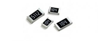
SMD resistors with tolerances of 5% and 2% are marked with the following three-character code:
| Resistance | Code |
| 0 Ohm (jumper) | 000 |
| from 1 Ohm to 9.1 Ohm | XRX (eg 9R1) |
| from 10 Ohm to 91 Ohm | XXR (for example 91R) |
A is the first digit in the resistor resistance value
B is the second digit in the resistor resistance value
C - number of zeros
| Code | Resistance |
| 101 | 100 Ohm |
| 471 | 470 Ohm |
| 102 | 1 kOhm |
| 122 | 1.2 kOhm |
| 103 | 10 kOhm |
| 123 | 12 kOhm |
| 104 | 100 kOhm |
| 124 | 120 kOhm |
| 474 | 470 kOhm |
SMD resistors with a tolerance of 1% are marked with four symbols.
| Resistance | Code |
| from 100 Ohm to 988 Ohm | XXXR |
| from 1 kOhm to 1 MOhm | XXXX |
A is the first digit in the resistor resistance value
B is the second digit in the resistor resistance value
C is the third digit in the resistor resistance value
D - number of zeros
| Code | Resistance |
| 100R | 100 Ohm |
| 634R | 634 Ohm |
| 909R | 909 Ohm |
| 1001 | 1 kOhm |
| 4701 | 4.7 kOhm |
| 1002 | 10 kOhm |
| 1502 | 15 kOhm |
| 5493 | 549 kOhm |
| 1004 | 1 mOhm |
Marking of SMD capacitors
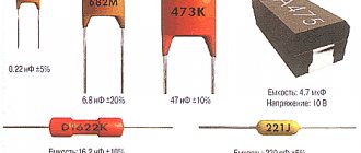
The first and second positions are significant digits of the capacitance value of the capacitor. The third is the number of zeros. The total value gives the capacitance in pF. For example, the capacitance of the capacitor shown in the figure above is 4,700,000 pF or 4.7 µF.
A two-character marking system is also used. The first is a letter representing a numeric value; the second symbol is a multiplier (power of ten). The total value gives the capacitance in pF.
| Letter | A | B | C | D | E | F | G | H | J | K | a | L |
| Meaning | 1.0 | 1.1 | 1.2 | 1.3 | 1.5 | 1.6 | 1.8 | 2.0 | 2.2 | 2.4 | 25 | 2.7 |
| Letter | M | N | b | P | Q | d | R | e | S | f | T | U |
| Meaning | 3.0 | 3.3 | 3.5 | 3.6 | 3.9 | 4.0 | 4.3 | 4.5 | 4.7 | 5.0 | 5.1 | 5.6 |
| Letter | m | V | W | n | X | t | Y | y | Z | |||
| Meaning | 6.0 | 6.2 | 6.8 | 7.0 | 7.5 | 8.0 | 8.2 | 9.0 | 9.1 | |||
| Number | 0 | 1 | 2 | 3 | 4 | 5 | 6 | 7 | 8 | 9 |
| Factor | 100 | 101 | 102 | 103 | 104 | 105 | 106 | 107 | 108 | 10-1 |
For example A5 = 1.0 x 105 = 100,000 pF = 0.1 µF, or f9 = 5.0 x 10-1 = 0.5 pF
For tantalum capacitors, the first symbol is often the voltage according to the table.
| Voltage (volts) | 4 | 6.3 | 10 | 16 | 20 | 25 | 35 | 50 |
| Code | G | J | A | C | D | E | V | H |
SMD_codebook
If you find an error, please select a piece of text and press Ctrl+Enter.
Transistors in KT-26 type housing
To designate the group, the following color markings of transistors are used: group A corresponds to a dark red dot, B - yellow, C - dark green, G - blue, D - blue, E - white, G - dark brown, I - silver, K – orange, L – light tobacco, M – gray.
The type is indicated by the symbols and colors shown below.
- KT203 corresponds to a right triangle (sides down and to the right) or a dark red dot.
- KT208 – small circle (there is no color marking for this type).
- K209 – rhombus (gray dot).
- K313 is a symbol that resembles an inverted letter T (orange dot).
- KT326 – inverted equilateral triangle (brown dot).
- KT339 – equilateral triangle (blue dot).
- KT342 – quarter circle (blue dot).
- KT502 – half a circle (yellow dot); KT503 – circle (white dot).
- KT3102 – right triangle with legs up and to the left (dark green dot).
- KT3157 – right triangle with legs to the left and down (no color designation).
- K366 – letter T (no color).
- KT6127 – inverted letter P.
- KT632 – no symbol (silver dot).
- KT638 – without symbol (orange dot).
- KT680 – letter G.
- KT681 – vertical stick.
- KT698 – letter P.
MOS transistors
| Marking | Device type | Marking | Device type |
| 6Z | MMBF170 | V01 | VN50300T |
| 701 | 2N7001 | V02 | VN0605T |
| 702 | SN7002 | V04 | VN45350T |
| S.A. | BSS123 | V0AJ | TP610T |
| SS | BSS138 | V50 | VP0610T |
- < Back
- Forward >
Comments
user 03/07/2017 15:53 and z56? he’s not here and I need to find out...
Quote
Update list of comments
Japanese JIS system
This system consists of symbols and contains five elements. The first digit corresponds to the type of semiconductor device: 0 – photodiode or phototransistor; 1 – diode; 2 – transistor. The second element is the letter S, it is placed on all elements. The following letter corresponds to the type of transistor: A – high-frequency PNP; B – low-frequency PNP; C—high-frequency NPN; D—low-frequency NPN; N – single-junction; J - field with N-channel; K - field with P-channel. This is followed by the product serial number (10 – 9999). The last, fifth, element is a modification of the device (often it may be missing). Sometimes a sixth character is also applied - this is an additional index (letters N, M or S), indicating the requirement of compliance with special standards. In the Japanese system, color coding of transistors is not used.
Marking of field-effect transistors
| Marking | Device type | Marking | Device type |
| 6A | MMBF4416 | C92 | SST4392 |
| 6B | MMBF5484 | C93 | SST4393 |
| 6C | MMBFU310 | H16 | SST4416 |
| 6D | MMBF5457 | I08 | SST108 |
| 6E | MMBF5460 | I09 | SST109 |
| 6F | MMBF4860 | I10 | SST110 |
| 6G | MMBF4393 | M4 | BSR56 |
| 6H | MMBF5486 | M5 | BSR57 |
| 6J | MMBF4391 | M6 | BSR58 |
| 6K | MMBF4932 | P01 | SST201 |
| 6L | MMBF5459 | P02 | SST202 |
| 6T | MMBFJ310 | P03 | SST203 |
| 6W | MMBFJ175 | P04 | SST204 |
| 6Y | MMBFJ177 | S14 | SST5114 |
| B08 | SST6908 | S15 | SST5115 |
| B09 | SST6909 | S16 | SST5116 |
| B10 | SST6910 | S70 | SST270 |
| C11 | SST111 | S71 | SST271 |
| C12 | SST112 | S74 | SST174 |
| C13 | SST113 | S75 | SST175 |
| C41 | SST4091 | S76 | SST176 |
| C42 | SST4092 | S77 | SST177 |
| C43 | SST4093 | TV | MMBF112 |
| C59 | SST4859 | Z08 | SST308 |
| C60 | SST4860 | Z09 | SST309 |
| C61 | SST4861 | Z10 | SST310 |
| C91 | SST4391 |
Types of recording
Transistor manufacturers use two main types of encryption: color coding and code marking. However, neither one nor the other has uniform standards. Each plant that produces semiconductor devices (transistors, diodes, zener diodes, etc.) adopts its own code and color designations. You can find transistors of the same group and type, manufactured by different factories, and they will be labeled differently. Or vice versa: the elements will be different, but the designations on them will be identical. In such cases, they can be distinguished only by additional characteristics. For example, by the length of the emitter and collector leads or by the color of the opposite (or end) surface. The markings of field-effect transistors are no different from the marks on other devices. The situation is the same with foreign-made semiconductor elements: each manufacturer uses its own types of designations.
Marking bipolar SMD transistors
| Designation on the body | Transistor type | Conditional analogue |
| 15 | MMBT3960 | 2N3960 |
| 1A | BC846A | BC546A |
| 1B | BC846B | BC546B |
| 1C | MMBTA20 | MPSA20 |
| 1D | BC846 | — |
| 1E | BC847A | BC547A |
| 1F | BC847B | BC547B |
| 1G | BC847C | BC547C |
| 1H | BC847 | — |
| 1J | BC848A | BC548A |
| 1K | BC848B | BC548B |
| 1L | BC848C | BC548C |
| 1M | BC848 | — |
| 1P | FMMT2222A | 2N2222A |
| 1T | MMBT3960A | 2N3960A |
| 1X | MMBT930 | — |
| 1Y | MMBT3903 | 2N3903 |
| 2A | FMMT3906 | 2N3906 |
| 2B | BC849B | BC549B |
| 2C | BC849C | BC549C/BC109C/MMBTA70 |
| 2E | FMMTA93 | — |
| 2F | BC850B | BC550B |
| 2G | BC850C | BC550C |
| 2J | MMBT3640 | 2N3640 |
| 2K | MMBT8598 | — |
| 2M | MMBT404 | — |
| 2N | MMBT404A | — |
| 2T | MMBT4403 | 2N4403 |
| 2W | MMBT8599 | — |
| 2X | MMBT4401 | 2N4401 |
| 3A | BC856A | BC556A |
| 3B | BC856B | BC556B |
| 3D | BC856 | — |
| 3E | BC857A | BC557A |
| 3F | BC857B | BC557B |
| 3G | BC857C | BC557C |
| 3J | BC858A | BC558A |
| 3K | BC858B | BC558B |
| 3L | BC858C | BC558C |
| 3S | MMBT5551 | — |
| 4A | BC859A | BC559A |
| 4B | BC859B | BC559B |
| 4C | BC859C | BC559C |
| 4E | BC860A | BC560A |
| 4F | BC860B | BC560B |
| 4G | BC860C | BC560C |
| 4J | FMMT38A | — |
| 449 | FMMT449 | — |
| 489 | FMMT489 | — |
| 491 | FMMT491 | — |
| 493 | FMMT493 | — |
| 5A | BC807-16 | BC327-16 |
| 5B | BC807-25 | BC327-25 |
| 5C | BC807-40 | BC327-40 |
| 5E | BC808-16 | BC328-16 |
| 5F | BC808-25 | BC328-25 |
| 5G | BC808-40 | BC328-40 |
| 549 | FMMT549 | — |
| 589 | FMMT589 | — |
| 591 | FMMT591 | — |
| 593 | FMMT593 | — |
| 6A | BC817-16 | BC337-16 |
| 6B | BC817-25 | BC337-25 |
| 6C | BC817-40 | BC337-40 |
| 6E | BC818-16 | BC338-16 |
| 6F | BC818-25 | BC338-25 |
| 6G | BC818-40 | BC338-40 |
| 9 | BC849BLT1 | — |
| A.A. | BCW60A | BC636/BCW60A |
| AB | BCW60B | — |
| A.C. | BCW60C | BC548B |
| AD | BCW60D | — |
| A.E. | BCX52 | — |
| A.G. | BCX70G | — |
| A.H. | BCX70H | — |
| A.J. | BCX70J | — |
| A.K. | BCX70K | — |
| AL | MMBTA55 | — |
| A.M. | BSS64 | 2N3638 |
| AS1 | BST50 | BSR50 |
| B2 | BSV52 | 2N2369A |
| B.A. | BCW61A | BC635 |
| BB | BCW61B | — |
| B.C. | BCW61C | — |
| BD | BCW61D | — |
| BE | BCX55 | — |
| B.G. | BCX71G | — |
| B.H. | BCX71H | BC639 |
| B.J. | BCX71J | — |
| B.K. | BCX71K | — |
| BN | MMBT3638A | 2N3638A |
| BR2 | BSR31 | 2N4031 |
| C1 | BCW29 | — |
| C2 | BCW30 | BC178B/BC558B |
| C5 | MMBA811C5 | — |
| C6 | MMBA811C6 | — |
| C7 | BCF29 | — |
| C8 | BCF30 | — |
| C.E. | BSS79B | — |
| CEC | BC869 | BC369 |
| CF | BSS79C | — |
| CH | BSS82B/BSS80B | — |
| C.J. | BSS80C | — |
| C.M. | BSS82C | — |
| D1 | BCW31 | BC108A / BC548A |
| D2 | BCW32 | BC108A / BC548A |
| D3 | BCW33 | BC108C/BC548C |
| D6 | MMBC1622D6 | — |
| D7 | BCF32 | — |
| D8 | BCF33 | BC549C/BCY58/MMBC1622D8 |
| D.A. | BCW67A | — |
| D.B. | BCW67B | — |
| DC | BCW67C | — |
| DE | BFN18 | — |
| DF | BCW68F | — |
| DG | BCW68G | — |
| D.H. | BCW68H | — |
| E1 | BFS17 | BFY90/BFW92 |
| E.A. | BCW65A | — |
| E.B. | BCW65B | — |
| E.C. | BCW65C | — |
| ED | BCW65C | — |
| E.F. | BCW66F | — |
| E.G. | BCW66G | — |
| E.H. | BCW66H | — |
| F1 | MMBC1009F1 | — |
| F3 | MMBC1009F3 | — |
| F.A. | BFQ17 | BFW16A |
| FD | BCV26 | MPSA64 |
| F.E. | BCV46 | MPSA77 |
| FF | BCV27 | MPSA14 |
| FG | BCV47 | MPSA27 |
| GF | BFR92P | — |
| H1 | BCW69 | — |
| H2 | BCW70 | BC557B |
| H3 | BCW89 | — |
| H7 | BCF70 | — |
| K1 | BCW71 | BC547A |
| K2 | BCW72 | BC547B |
| K3 | BCW81 | — |
| K4 | BCW71R | — |
| K7 | BCV71 | — |
| K8 | BCV72 | — |
| K9 | BCF81 | — |
| L1 | BSS65 | — |
| L2 | BSS70 | — |
| L3 | MMBC1323L3 | — |
| L4 | MMBC1623L4 | — |
| L5 | MMBC1623L5 | — |
| L6 | MMBC1623L6 | — |
| L7 | MMBC1623L7 | — |
| M3 | MMBA812M3 | — |
| M4 | MMBA812M4 | — |
| M5 | MMBA812M5 | — |
| M6 | BSR58/MMBA812M6 | 2N4858 |
| M7 | MMBA812M7 | — |
| O2 | BST82 | — |
| P1 | BFR92 | BFR90 |
| P2 | BFR92A | BFR90 |
| P5 | FMMT2369A | 2N2369A |
| Q3 | MMBC1321Q3 | — |
| Q4 | MMBC1321Q4 | — |
| Q5 | MMBC1321Q5 | — |
| R1 | BFR93 | BFR91 |
| R2 | BFR93A | BFR91 |
| S1A | SMBT3904 | — |
| S1D | SMBTA42 | — |
| S2 | MMBA813S2 | — |
| S2A | SMBT3906 | — |
| S2D | SMBTA92 | — |
| S2F | SMBT2907A | — |
| S3 | MMBA813S3 | — |
| S4 | MMBA813S4 | — |
| T1 | BCX17 | BC327 |
| T2 | BCX18 | — |
| T7 | BSR15 | 2N2907A |
| T8 | BSR16 | 2N2907A |
| U1 | BCX19 | BC337 |
| U2 | BCX20 | — |
| U7 | BSR13 | 2N2222A |
| U8 | BSR14 | 2N2222A |
| U9 | BSR17 | — |
| U92 | BSR17A | 2N3904 |
| Z2V | FMMTA64 | — |
| ZD | MMBT4125 | 2N4125 |
