A pass-through switch is a device that can be used to control one light source from different places. These devices are installed in long corridors, as well as in passages and on stairs. Recently, they have increasingly begun to be used in bedrooms: one switch at the entrance to the room, and the second near the bed. Their convenience lies in the fact that in order to turn off the light in the corridor or room, there is no need to return. They are also used in offices: in this case, sitting down at the table and turning on the table lamp, you can turn off the top lamp without leaving your workplace. In this article we will talk about how to make a pass-through switch from an ordinary one yourself.
What is a pass-through switch used for?
The main feature of a pass-through switch is the ability to turn on the light in one place, go to another and turn off the light there.
So conveniently and comfortably, any number of people can move in any direction and sequence. That is why the device is called a pass-through device. In practice, this is very convenient to go through, for example:
- from the garage to the house down the street;
- follow the long corridor;
- climb the stairs from the first floor to the second;
- turn on the light at the bedroom door, walk to the bed and turn it off.
In all four cases, a pair of pass-through switches will help us out. The convenience of using such devices in large apartments and houses is especially noticeable. To control lighting in more complex combinations with several lamps and control points, pass-through switches with different numbers of keys and internal circuits are used.
Design Features
Based on the number of switched electrical circuits, devices can be one-, two-, or three-key. Terminals with screw or spring terminals. The design also depends on the functional purpose. The types of devices differ when used for external or internal wiring.
Such electrical equipment is designed to turn one or a group of lamps on and off from different places. There is no need to go back to the other end of the room to press a key. Electrical appliances are used in large apartments, in corridors and on stairs, when lighting garden paths, in the bedroom. In addition to convenience, this saves energy.
Walk-through switches are also used in concert halls, stadiums, underground passages and tunnels, and in the entrances of high-rise buildings.
Pass-through type switch design
Externally, a main switch is no different from a regular switch, except for the presence on the key of a conventional image in the form of two triangles and a diagram of the device on the back side of the dielectric base.
Inside the pass-through switch there are three contacts: two fixed and one movable (changeover), driven by the external key of the device. The changeover contact has two possible operating positions - on one of the fixed terminals. By pressing a key, the movable contact moves from one terminal to another, breaking one circuit and closing the second.
This design feature of the pass-through switch is the basis for a network design in which one lighting fixture can be controlled from two different locations. The neutral and grounding wires from the distribution box are connected to the lighting device, and a break is made in the phase conductor with two pass-through switches, between which two alternative lines are laid.
The difference between a marching switch and a regular switch
The pass-through apparatus consists of the same components as a regular one:
- grounds;
- connecting terminals (terminals);
- mobile system;
- contact group;
- decorative details: keys (there may be several) and frames.
The difference lies in the design of the contact group. A typical key switch contains one moving contact and one fixed contact. In one position the circuit is closed, in another it is open. The pass-through device has a changeover contact group and consists of two fixed and one movable (changeover) contacts. In one position one circuit is closed (the other is open), in the other it is the other way around. The second circuit is connected, the second is open. Therefore, such devices are rightly called switches.
The difference between a main switch and a key switch.
It is not always possible to distinguish a pass-through switch from a key device by appearance - not all manufacturers bother to apply markings in the form of a double arrow or a flight of stairs on the front panel. Therefore, you can determine the type of switch from the back. The pass-through switch has at least three terminals , and a diagram of the contact group is printed on the back.
The back part of the sustainer instrument.
Some manufacturers, instead of a diagram, put the letter designation of the terminals on the back of the switch. One option: the changeover contact is designated by the letter L, fixed contacts A1 and A2. Other marking options are also possible - a unified designation standard has not been established, although the letter designation is becoming less and less common.
| Switch type | Number of keys | Terminal markings |
| Legrand Valena | 1 | Scheme |
| Lezard | 2 | Scheme |
| Makel Mimoza | 2 | Scheme |
| Champagne Simon | 2 | Letters |
Like conventional key devices, switches come in single-key and two-key (less often three-key) types. In each case, they manage the appropriate number of contact groups.
Operating principle of a pass-through switch
Unlike the usual models of two- and one-key switches for turning on lighting, pass-through switches provide two on positions. To operate the circuit, two pass-through switches are used, with which you operate the lighting lamps.
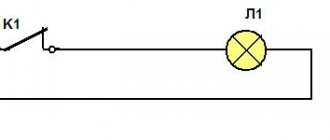
A schematic diagram of the operation of such an electrical circuit is shown in the figure below:
Figure 1: operating principle of a pass-through switch
As you can see, in the diagram, the phase wire is connected from the electrical wiring to the switches, and the neutral wire is led directly to the lamp or other lighting equipment. If you trace the connection from the distribution box, the phase is supplied to the input of the first pass-through switch. Next, two independent wires connect the terminals A and B of the first device to the terminals of the same name of the second switch. From the output terminal of the second switch, the phase is supplied to the lamp output. The second terminal of the lamp is connected by the neutral wire.
Of course, the above connection diagram requires additional cable costs to connect the switches to each other, but its functionality more than justifies it. Due to its design features, such a switch does not break the circuit in any position, so it is more correct to call it a switch.
In everyday life, due to the use of such switches on staircase landings to disconnect flights from different points, they are also called marching switches.
If you decide to implement such a scheme at home or in the office, but do not want to overpay for a pass-through switch, it can also be made from a cheaper two-key device. Next, we will look at two techniques that will allow you to make a pass-through switch with your own hands.
DIY marching switch
The prevalence of self-manufacturing of pass-through switches is due to the fact that they are much more expensive than conventional ones, and are not available for sale in every household electrical equipment store. The most common method of manufacturing marching switches is to assemble them yourself from ordinary devices - single-key and two-key in various combinations.
Interesting read: what are capacitors?
Pass-through switch - from a conventional single-key switch
To control one lighting device (without dividing the lamps in it into groups), a single-key main switch is used. Unlike the model for hidden wiring, a pass-through device for outdoor installation can be difficult to find on sale, so it is the surface-mounted marching switches that are most often assembled independently.
It will be interesting➡ How to ring a transistor correctly?
A pass-through single-key switch for external wiring can be assembled from two ordinary ones - also single-key. In this case, it is necessary that the switches are of the same model, and the arrangement of internal components in the housing is symmetrical. As a rule, products from one manufacturer are used for assembly. A proven option are switches from Schneider Electric, on one of which we will consider this operation.
Using a screwdriver with a narrow blade, the key is pryed up and removed from the housing, after which the dielectric base is pushed out of the switch by pressing on the front part. The extruded base is separated from the standard plastic socket box. Using the same screwdriver, 4 latches around the perimeter are snapped off, and the base is divided into two parts, each of which is symmetrical about the vertical axis.
Connecting a pass-through switch.
All the operations described are carried out with the second switch, but only in order to remove the rocker arm from it - metal contacts and a graphite rod. The removed rocker arm is turned over around its longitudinal axis and installed in the base of the first switch - in ready-made grooves next to the existing contacts, but in the opposite direction.
A second rod is also inserted into the paired socket, after which the dielectric base is assembled - a jumper (common contact) is installed between the two contacts on one side, the two halves are folded and snapped into place. Upon completion of assembly, it is necessary to “ring” the pass-through switch with a tester at different positions of the key. Accordingly, this device is paired with another one – also from two ordinary single-key devices.
How to use a pass-through switch.
Main switch - from a regular two-key switch
For this method of manufacturing a pass-through switch, you will need one two-key switch. Assembling a main product for hidden wiring is most easily accomplished by reworking products from the Anam, Legrand or Panasonic brands, which have a modular design. To remake the switch, the keys are removed from it, after which access to the modules mounted on guides in the housing appears. One of the modules needs to be removed and, turning it upside down, again installed in its original place.
The fit of the module must be pinpointed with drops of hot-melt adhesive, since in this position its latches may not coincide with the standard grooves. The switch is assembled in the reverse order and a device is obtained, the modules of which, after turning one of them, turn out to be working in antiphase. Therefore, on the back side of the switch it is necessary to install a jumper between the contacts on one side - it will be the common contact of the device. The two keys that are in place must be firmly connected to each other, for example, by filling the gap between them with a sealant of a suitable color.
Material on the topic: what is an electrical circuit.
Pass-through two-key switch
A two-key main switch is designed to control from several places two groups of lamps of a lighting fixture, for example, tiers of a chandelier. Pressing one key on the switch will supply power to one group (tier), and the second to the other. The product consists of two single-key pass-through switches mounted in one housing. Each key has one input and two outputs, for a total of 6 contacts per switch in total.
Thus, single-key and two-key pass-through switches have a common operating principle, but connecting a dual device is more complicated - the phase is supplied to both inputs of the first two-key switch, which is connected to the second by four conductors. To avoid mistakes, it is better to study the methods of connecting two-key marching switches using diagrams, here is one of them:
Pass-through two-key switch
Assembling and installing a two-key main switch with your own hands is only possible when using two converted devices mounted on the wall next to each other and connected accordingly.
It will be interesting➡ Options for connecting circuits for pass-through switches
To control two groups of chandelier arms from two different places, you will need four converted switches. The cost of conventional devices for assembling two-key switches in this case will exceed the price of a finished switch from the manufacturer.
The finished product outperforms the one assembled from two converted ones in terms of compactness and aesthetics, which is why they very rarely resort to self-assembly of pass-through two-key switches.
Differences between pass-through and traditional switch
The difference between a pass-through and a regular switch (rear view)
The switches are no different in appearance. The internal structure of a conventional one is equipped with one input and output. Can have up to three keys, allowing you to control multiple lighting sources. Most often they are installed near the entrance to the room. The connection is made using two terminals.
A classic checkpoint has two exits and one entrance. In this case, the electric current is not interrupted, but is redirected to any other output. There is a diagram underneath the product body. The single-key pass-through is equipped with three-wire switching and three terminals with copper contacts. This is a switch that redirects the current to other areas.
By design, installation method and type of control, switches can be:
- keyboards;
- push-button;
- sliders;
- traction;
- toggle switches.
They are also classified depending on voltage and current, degree of protection, and climatic conditions in which they are installed.
It is important not to confuse an electrical appliance with a changeover or crossover device. On the pass key there is a vertical triangle, in the rest it is located in the horizontal direction.
Where is the best place to install?
It is very convenient to install such a unit in places where you do not need to constantly connect electrical appliances to an outlet.
Before you connect a double switch for the corridor and the adjacent combined bathroom (bathroom with toilet), think about installing a common unit with an outlet? One button turns on the light in the hallway, the second in the bathroom, and the socket can be used to connect a hair dryer, electric drill, vacuum cleaner, or charge a mobile phone.
The block, which has a socket with a one-key switch, is suitable for installation in garages, sheds, basements, gatehouses, change houses and other outbuildings. In this case, just one switch key is enough to light up the lamp in the room, and the socket is useful for connecting a power tool, kettle, fan or radio.
In other rooms (living room, kitchen, bedroom, children's room), connecting a combined socket-switch unit is unlikely to be advisable. It will not have the aesthetic appearance to fit into the overall interior. After all, the light switch is usually installed at the entrance to the room. Imagine how ugly it will be if the cord of a TV, computer, refrigerator or air conditioner runs here, to the outlet.
Therefore, before you connect a unit that combines an outlet with a switch, think carefully about where you want to put it, and whether it is needed there.
Reworking the device
The process of converting a simple switch into a walk-through is accessible to everyone with their own hands. Its appearance is no different from its brother. It can have 1 key, 2 or more. The difference between these devices is visible only from the inside. The pass-through serves to switch circuits, so it is more correct to call it a switch. Most often at home you have to use a regular single-key main switch. In large rooms, a device with several keys is sometimes required.
The modification consists of adding a contact: instead of 2 you need to put 3. How to connect a pass-through switch to the network? A three-core cable must be laid between a pair of devices. The phase always goes to the switch, zero to the light fixture. Nowadays, photo relay circuits are made using KT315B transistors or Q6004LT. Our task is to make a pass-through switch from an ordinary marching switch with our own hands.
Selecting a three-key switch
When choosing a three-circuit switch, you should carefully examine it. You should study the physical characteristics and make sure that the wiring diagram is present. A high-quality three-key player has the following characteristics:
- There are no scratches, dents or damage on the case.
- The keys work easily and do not stick.
- Turning on 1 key is accompanied by a click.
- The core and its clamps function properly.
For rooms with high humidity levels, you need to purchase a device that has special protection. Cores with screw and clamp terminals have additional advantages. This will make installation easier and extend the life of the switch.
It is not recommended to buy a device with any defects. Not only uninterrupted lighting, but also safety directly depends on this.
Connection diagram of switches for controlling one light source from several places
To be able to control the lighting circuits, we need the following materials:
- distribution box with a diameter of 80 mm;
- 2 pieces of pass-through switches;
- flexible cable type PVSng or VVGng 3x1.5;
- 5 pcs of WAGO type terminal clamps for 2–3 contacts (or a soldering iron with tin and rosin);
- 2 pcs socket boxes for concrete (plasterboard).
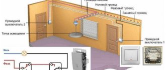
The connection diagram for a pass-through switch made from the above materials will be as follows:
As we see in the above photo, to control lighting using pass-through switches, the neutral power wire in the terminal box is connected to the first output of lamps No. 1 and No. 2. The phase wire of the supply circuit in the distribution box is connected to terminal No. 1 of pass-through switch No. 1. The remaining two outputs of switch No. 1 are connected in the box to terminals No. 2 and No. 3 of switch No. 2, respectively. Next, pin No. 1 must be connected to the second free end of the lighting lamps.
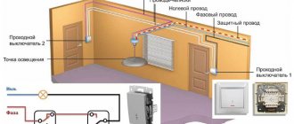
The above circuit will allow you to fully control the lighting system, however, the above circuit does not protect a person from electric shock. For these purposes, the following connection diagram for the pass-through switch is used:
As we can see from the above photo, the main difference between the two schemes is the use of a three-core cable, which, in addition to phase and neutral, also contains a third grounding conductor. It allows, if the insulation in equipment or cable and wire products is damaged, to divert the resulting potential to the ground loop and cause the circuit breaker to trip.
Instructions for replacing the light switch
Before replacing a new light switch in an apartment, you need to dismantle the old keypad and make sure the wiring is in good condition.
How to remove the old switch?
Dismantling the old switch is carried out in accordance with the step-by-step instructions:
- Remove the key and top cover.
- Disconnect the wires using a screwdriver, unscrewing the bolts on the terminals.
- Apply power to the distribution panel and locate the phase wire using the indicator.
- Turn off the mains voltage.
- Mark the phase with insulating tape or another method.
- Loosen the screws holding the spacer tabs.
- Remove the device from the socket.
Scheme for dismantling the old switch
In some cases, the sequence will be reversed - the wires can be disconnected only after the switch is removed. This depends on the design features of the device.
Dismantling the external switch is carried out in a similar manner. The only difference is that instead of loosening the screws of the spacer legs, the screws that secure the device to the wall are unscrewed.
Video instructions for dismantling the old switch can be viewed on the channel “Guys from Stone. Do-it-yourself apartment renovation.”
We are preparing for connection
Before connecting a new device, you must complete the following preparations:
- Loosen the screw terminals so that the wires fit easily into the hole.
- Unscrew the screws of the spacer tabs so that the switch fits freely into the socket box (this operation is not required for outdoor devices).
- Strip the wires when replacing them (if the condition of the old electrical cable is good, there is no need to strip it).
Diagram and connection with one button
After everything is prepared, you can install a breaker with one key, following the detailed algorithm:
- Examine the markings on the terminals of the single-key switch. The phase wire must be connected to contact L, the second end of the cable to connector 1, respectively.
- Insert the bare wires into the contact holes and tighten the terminal screws. Do not apply too much force, otherwise you may break the thread.
- Install the switch in the socket box strictly horizontally without distortion.
- Secure the device with the sliding tabs by tightening the screws.
- Check the correct operation of the lighting fixtures by turning on the circuit breaker on the electrical panel.
- If the switch operates correctly, install the cover and keys.
Diagram and connection with two buttons
Algorithm for installing a switch with two keys:
- Connect the phase wire to contact L, the remaining two ends to connectors 1 and 2 in accordance with the markings.
- Tighten the fastening screws (this operation is not necessary on spring terminals).
- Place the switch in the socket box.
- Tighten the screws of the sliding legs, eliminating even minimal gaps.
- Make sure that the device works correctly by turning on power.
- Install the cover and both keys.
Step-by-step instructions for installing a two-key switch are given in the photo gallery:
Non-standard situation
There are often cases when the wire inside the socket box is too short. It is not long enough to connect a new switch. Such unusual situations arise in old houses, where electrical appliances have already been replaced several times, and the wiring has become unusable. In this case, the cable must be extended.
This will require additional tools and consumables, namely:
- hammer;
- chisel;
- putty knife;
- two-core wire 10–15 cm long;
- a little putty or plaster;
- insulating tape.
Only wires of the same types can be spliced together. A copper cable cannot be connected to an aluminum one - this can lead to oxidation in the contact area, decreased conductivity and burnout of the wiring.
Cable extension is performed in the following sequence:
- Determine in which direction the cable is laid in the wall.
- Carefully release a piece of wire about 10 cm long using a hammer and chisel.
- Cut off the damaged cable section with pliers.
- Strip the ends of the new and old cable, completely removing the insulation in a section of at least 2 cm.
- Tightly twist the protected wires together.
- Wrap the exposed areas tightly with insulating tape.
- Place the connected cable into the channel.
- Cover the damaged area with plaster or putty.
After the solution has completely hardened (after 15–20 minutes), you can continue to install the new switch.
Connection diagram for a pass-through switch with 2 places
The circuit of a pass-through switch from two places is carried out using two pass-through single-key devices that work only in pairs. Each of them has one contact at the entry point, and a pair at the exit point.
Before connecting the pass-through switch, the connection diagram clearly displays all the stages; you should de-energize the room using the appropriate switch located in the control panel. After which it is necessary to additionally check that there is no voltage in all wires of the switch. To do this, use a special screwdriver.
Helpful advice! A similar check must be performed at the installation sites of switching devices.
To complete the work you will need: flat-head, Phillips and indicator screwdrivers, a knife, side cutters, a level, a tape measure and a hammer drill. To install switches and lay wires in the walls of the room, appropriate holes and grooves must be made in accordance with the device layout plan.
Unlike conventional switches, pass-through switches have not two, but three contacts and can switch the “phase” from the first contact to the second or third
Wires must be laid at a distance of at least 15 cm from the ceiling. They can be placed not only in a hidden way, but also placed in trays or boxes. This installation makes it possible to quickly carry out repair work in case of cable damage. The ends of the wires must be inserted into installation boxes, in which all connections are also made using contactors.
Converting a double switch into a triple device
In order to make the most of switching products, some users try to make a triple switch out of a double switch. Such a rework does not require much effort or a lot of time. You just need to replace the double device with a new model:
- Buy a switch with three keys in the store.
- Dismantle the old double product.
- Install a new triple switch in its place.
You can try to hide it in the thickness of the walls, but the gating procedure is associated with large labor costs for making grooves for the cable. It is much cheaper and easier to lay pieces of plastic cable channel from the outlet to the box, and from it to the chandelier. After fixing it on the walls (the covers are first removed), the wire sections are laid to the required places and then connected to the free terminals. Upon completion of installation, all that remains is to close the cable channels with covers and check the switch for functionality
Three-key switches are universal devices through which it is possible to significantly expand the functionality of switching units.
Changeover switches - lighting control circuit from 3 places
But what if you want to control one lighting from three or more points. That is, there will be 3, 4, etc. switches in the circuit. It would seem that you need to take another pass-through switch and that’s it.
However, a switch with three terminals will no longer work here. Since there will be four connected wires in the junction box.
Here a changeover switch, or as it is also called a cross, cross, or intermediate switch, will come to your aid. Its key difference is that it has four exits - two from below and two from above.
And it is installed precisely in the gap between two passageways. Find in the junction box two secondary (not main) wires from the first and second pass-through switch.
We do it ourselves
If your store does not sell specialized switches, then there is no need to be upset - you can make them yourself. Let's look at how to make a pass-through switch from a regular switch. To do this, you need to buy one classic one-button switch and one two-button switch. Choose devices from the same manufacturer and the same size. Then, in the two-key mechanism, swap the terminals so that the circuits can be turned on and off independently. It turns out that in one position the first circuit is always turned on, in the second - the second. Then swap the two keys for one, and your switch is ready - it can be installed anywhere.
If you need to install three switches, you will need more complex 4-pin systems - two for input and two for output. Such a circuit must be powered with a four-wire wire, connecting the contacts in pairs.
Now you know how to make a pass-through light switch. To make all questions disappear, look at our device connection diagrams.
How does a pass-through switch work?
Disadvantages of pass-through devices
You should always check the circuit before connecting. The input and output contacts of the changeover switch can be located differently
The position of the keys does not allow you to determine whether the system is turned off or on. For example, it may not be possible to immediately understand whether the lights are turned off or a light bulb has burned out. It is impossible to control a lighting device from different places at the same time. A large number of connected devices means a lot of twists in the junction box. Connection errors force you to reassemble the entire circuit.
The pass-through switch has many functionalities. But to connect it, you need to purchase another device. The number of connecting wires also increases, which increases the overall cost of the system. An ordinary switch has a relatively low price, but loses in functionality.
Decorative and functional facial details
The housing structure also contains fastening elements and a number of front parts. This is a plastic frame and three key inserts.
- The frame is necessary to cover the edges of the wall recess into which the switch is mounted.
- It also effectively protects the wallpaper from sweat and dirt, which are present to one degree or another on the hands.
- The wider the installed frame, the cleaner the wall around the switch will be after 1-2 years of operation.
- These parts are detached without much effort, after which they are just as quickly fixed on the spacer fasteners.
Original industrial design
A three-circuit light switch is better than analogues with fewer keys for a number of reasons. Firstly, such a device looks much more original, which is pleasing to the eye and brings zest to the interior, which is sorely lacking in the era of widespread minimalism and pragmatism.
You can be convinced of the unusual design of this device and its aesthetic superiority by studying a couple of dozen photos of three-key switches.
Connection errors
Many people make a mistake at the stage of searching and connecting the common terminal in the pass-through switch. Without checking the circuit, they naively believe that the common terminal is the one with only one contact. They assemble a circuit in this way, and then for some reason the switches do not work correctly (they depend on each other).
Remember that on different switches the common contact can be anywhere!
And it is best to call it, what is called “live”, with a tester or an indicator screwdriver.
Most often, this problem is encountered when installing or replacing pass-through switches from different companies. If everything worked before, but after replacing one circuit the circuit stopped working, it means the wires were mixed up.
But there may also be an option that the new switch is not pass-through at all. Also remember that the lighting inside the product cannot in any way affect the switching principle itself.
Another common mistake is incorrectly connecting crossovers. When both wires are placed from pass-through No. 1 to the upper contacts, and from No. 2 to the lower ones. Meanwhile, the cross switch has a completely different circuit and switching mechanism. And you need to connect the wires crosswise.
Advantages
From installing such a triple switch you will receive the following advantages:
- Externally, one switch with three keys looks more compact and more aesthetically pleasing than three single ones.
- Laying electrical wires to the connection point will be less expensive in terms of labor and money.
- You will need to make one technological niche in the wall for the mounting box instead of three.
- Economic effect. For example, if your chandelier has 3-4 light bulbs, then turning on a single-key switch ensures that all of them work at once, while consuming maximum electricity. But such illumination is not always necessary; dim light is sufficient. If you install a 3-key household switch for such a chandelier, then, if necessary, one or two lamps are turned on, thereby saving almost half of the electricity.
Connecting one lamp to a single-key model
Let us describe a method for connecting a light bulb to a switch with one control button. Some types of symbols indicated on the device:
- if number 1 is marked, this is an input phase contact, number three is marked as an outgoing phase contact;
- letter designation L – incoming phase contact, number 1 – outgoing phase;
- L – input, arrow – exit.
The following tools will be useful during the work process:
- knife to scrape insulation from wires;
- screwdrivers with insulated handles: indicator and Phillips;
- marker;
- insulating tape.
- Turn off the electricity at the machine or panel.
- The switch is mounted where the phase break was provided. The “zero” wire goes to the light bulb.
- Strip the insulation from the wires. The ends should be trimmed 8-10 mm on each side.
- We connect the phase to the input contact of the switch. With the standard location of the switch, the input terminal should be located at the bottom.
- We conduct the phase from the lighting fixtures to the outgoing contact terminals.
- Press the wire to the contact, tighten the screws. The core should move 1-2 mm away from the contact.
- The phase from the distribution box is connected to the phase contact of the switch.
- We run wires from the switch to the lamp. We take the zero directly from the switchboard to the rim of the base. The phase passes through the switch and is connected to the central contact of the light bulb.
- Insulation of twisted wires.
- Starting the machine.
- Checking the system's functionality.
Under no circumstances should the switch be connected to zero. The load on the device will increase too much. This will lead to rapid burnout of contacts.
By installing the switch on a phase, the supply of current to the end user can be quickly interrupted. This is relevant in case of emergencies. Setting the switch to “zero” will not give the desired result in emergency conditions. Disabling in this case will only open the circuit, but will not lead to de-energization of the entire system.
Blitz tips
- When carrying out installation work, in order to make sure that there is no electric current, use an indicator screwdriver. Holding this tool in your right hand, you need to touch the end of the screwdriver with your index finger, and touch the exposed conductor with its sharp part. If at this moment the indicator starts to glow, then there is dangerous voltage in the circuit.
- In order for pass-through devices to be convenient to use, the most suitable height for their installation should be about 90 cm. Electrical fittings are installed at a distance of 20 cm from the doorway.
- In the bedroom, pass-through elements of electrical fittings allow you to turn off the lighting without getting out of bed; for this purpose, one of the devices is installed directly next to the bed, and the other, near the doorway.
- When installing electrical fittings outdoors, you should purchase devices that are designed for outdoor installation. Such devices must have a degree of protection of at least IP44.
- During installation work, before turning off the electricity, using an indicator screwdriver, the phase wire that will be connected to the switch is determined. This installation method makes it easy to disconnect the socket to replace the light bulb.
- Although the system uses two devices, the maximum connected power should not exceed the workload of one device. The standard current consumption of such devices is 10 A.
- When connecting 2 and 3 key pass-through devices, to avoid confusion with the wires, use wires of the same color in pairs. For example, at the output of one key of the first device there are two blue wires, and from the second key there are yellow wires, which are connected in pairs to the terminals of the second element.
- It is not recommended to connect wires in junction boxes using the twisting method. For high-quality connections, insulated copper sleeves or terminals with screw clamps are used.
- When carrying out work, safety regulations must be observed. If you have doubts about your abilities, you should contact a professional electrician who will perform all the necessary work.
Toggle switch option with hidden mechanism
Reversing switches are used in public spaces of large area and those that have opposite exits (in passage galleries, tunnels, corridors). In most cases, pass-through switches are installed in their usual place at the entrance and exit. In the apartment, switches are placed in a convenient place, for example, one is at the entrance to the bedroom, and the second is located near the bed.
An internal switch is installed if hidden wiring is installed in the walls along pre-made grooves. A corrugated hose is placed over the wires. A mounting hole is drilled into the thickness of the wall for the switch using a crown. The box body is secured using plaster or self-tapping screws.
The box for installing a pass-through type switch is spacious, since it contains bundles of wires and cables to other devices and lamps. After laying the wire from the distribution board, the wires are connected to the contacts of the switch according to the developed diagram.
The lamp contacts are connected to the neutral wire. The phase is connected to one of the supply voltages. The contacts are connected in series through a junction box in the room, after which they are routed to all lighting fixtures. For ease of operation, cables are marked or products of different colors are immediately used.
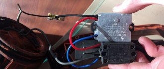
Remaking a two-key switch
To disassemble the device, use a screwdriver to pry up the keys, unscrew the fixing bolts from the front, unscrew the bolts of the fixing structure from the back, and carefully remove the top cover. At this stage, firstly, we check the removability of the contact with the clamp (it’s better to ask the seller before disassembling the switch), secondly, we check the functionality of the switch with the rocker arm rotated 180 degrees (it’s better to read on the Internet). If both conditions are met, you can begin to create a pass-through switch.
We turn the rocker over and combine the buttons into a single synchronously moving structure. All that remains is to check the functionality.
Intermediate relay
The extreme option we considered today would be to use a single-key switch in a group with a special intermediate relay. This scheme is rather theoretical, because its practical implementation is extremely problematic, and its operation creates several technical nuances.
The main nuance is that the relay must work constantly, even if this is a small financial waste, but we introduce a permanent consumer into the system, which little but always “eats” our electricity and “turns” the meter.
The transition relay performs the function of changeover contacts, and the single-key switch, in such a circuit, plays the role of a coil switching controller.