An asynchronous motor is divided into two groups, which depend on the method of rotor winding:
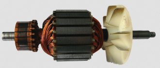
The rotor is fixed to the motor shaft, on which the bearings are fixed. This entire structure is located in bearing shields.
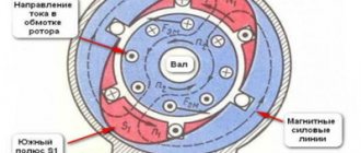
Operating principle of an asynchronous motor
The stator and rotor fields are connected and form a common rotating magnetic field of the motor, which interacts with the current in the rotor winding and generates force according to the left-hand rule. It turns the rotor in the direction of rotation of the magnetic field.
The device is called asynchronous due to the fact that the rotational speed of the magnetic field is several times greater than the rotor speed.
Expert opinion
It-Technology, Electrical power and electronics specialist
Ask questions to the “Specialist for modernization of energy generation systems”
Connecting a motor with a star and a triangle - All about electrics in the house In networks of 220-380 V, the voltage between phases U1, U2 and U3 will be equal to 380 V, and the voltage between zero and phase U4, U5 and U6 will be equal to 220 V. Ask, I’m in touch !
What are "star" and "triangle"
Typically, asynchronous motors are used with three windings, which can be connected in two ways - star (symbol "Y") or delta (Δ or D). The connection circuit must ensure normal operation of the engine at the available supply voltage.
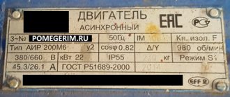
The first thing you need to consider when choosing a circuit is the information on the engine nameplate. It indicates the parameters for both schemes. The most important parameter is the supply voltage. The voltage of the “star” is 1.73 times (more precisely, the square root of 3) greater than that of the “triangle”. For example, if it is indicated that the supply voltage of a motor connected according to the “star” circuit is 380 V, then you can say for sure, without even looking at the nameplate, that to turn on the “delta” circuit you need a voltage of 220 V. In this case, the voltage is 380 B corresponds to the line voltage in a standard network, and the motor can be connected in a star configuration via a contactor or via a frequency converter. The same is true for cases when the “delta” voltage indicated on the nameplate is 380 V. Then, multiplying by 1.73, we obtain the “star” voltage equal to 660 V.
These two types of motors, differing in supply voltages (220/380 and 380/660 V), are used in practice in the vast majority of cases and have their own connection features, which we will consider below.
How to connect a 380V to 220V electric motor
There are situations in life when you need to start a 3-phase asynchronous electric motor from a household network. The problem is that you only have one phase and a “zero” at your disposal.
What to do in such a situation? Is it possible to connect a three-phase motor to a single-phase network?
If you approach your work wisely, everything is possible. The main thing is to know the basic schemes and their features.
Design features
Before starting work, understand the design of the IM (induction motor).
The device consists of two elements - a rotor (moving part) and a stator (fixed unit).
The stator has special grooves (recesses) into which the winding is placed, distributed in such a way that the angular distance is 120 degrees.
The windings of the device create one or more pairs of poles, the number of which determines the frequency with which the rotor can rotate, as well as other parameters of the electric motor - efficiency, power and other parameters.
When an asynchronous motor is connected to a three-phase network, current flows through the windings at different time intervals.
A magnetic field is created that interacts with the rotor winding and causes it to rotate.
In other words, a force appears that turns the rotor at different time intervals.
If you connect the IM to a network with one phase (without performing preparatory work), the current will appear in only one winding.
The torque generated will not be enough to move the rotor and keep it spinning.
That is why, in most cases, the use of starting and operating capacitors is required to ensure the operation of a three-phase motor. But there are other options.
How to connect an electric motor from 380 to 220V without a capacitor?
As noted above, to start an electric motor with a squirrel-cage rotor from a single-phase network, a capacitor is most often used.
It is this that ensures the device starts at the first moment after the single-phase current is supplied. In this case, the capacity of the starting device should be three times higher than the same parameter for the working capacity.
For motors with a power of up to 3 kilowatts and used at home, the price of starting capacitors is high and sometimes comparable to the cost of the motor itself.
Consequently, many are increasingly avoiding containers used only at the moment of start-up.
The situation is different with working capacitors, the use of which allows you to load the motor at 80-85 percent of its power. If they are absent, the power indicator may drop to 50 percent.
Classic star/delta design
When powered “directly” from an industrial network with a linear voltage of 380 V, both types of motors are suitable. You just need to make sure that the winding circuit is assembled for the required voltage.
However, in practice, the second type of drive (380/660 V) is used for power supply in the star/delta circuit. This circuit is used to reduce the starting current of powerful motors, which can exceed the operating current several times. Despite the fact that this current is short-term, during acceleration the supply network and the drive experience significant electrical and mechanical overloads - after all, in the first fraction of a second, the motor current can be 10 times higher than the nominal value, gradually decreasing during the acceleration process.
The star/delta connection diagram is given in many sources, so let us just briefly recall how it works.
To make the starting process more gentle, first a voltage of 380 V is applied to the motor windings connected in a star configuration. Since the operating voltage of this circuit must be higher (660 V), the motor runs at reduced power. A few seconds later, after the drive spins up, the “triangle” is turned on, for which 380 V is the operating voltage, and the engine reaches rated power.
We have looked at the classic circuit, and now we will look at in what cases to use connecting motors in star and delta when powered by a frequency converter.
Star or triangle. Optimal connection of an asynchronous motor
In practical work, it is customary to use two main methods of connecting three-phase electric motors to the electrical network. These connection methods are called: “star connection” and “delta connection”.
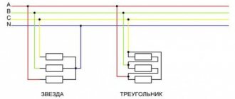
When a three-phase electric motor is connected using the star connection type, then the ends of the stator windings of the electric motor are connected at one point. In this case, three-phase voltage is supplied to the beginning of the windings. Below, in Figure 1, the connection diagram for a star asynchronous motor is clearly illustrated.
When a three-phase electric motor is connected using the “delta” connection type, then the stator windings of the electric motor are connected in series one after another. In this case, the beginning of the subsequent winding is connected to the end of the previous winding, and so on. Below, in Figure 2, the connection diagram for a delta asynchronous motor is clearly illustrated.
The electric motor control circuit is shown in Figure 3.
Another version of the electric motor control circuit is as follows (Fig. 4).
The NC (normally closed) contact of time relay K1, as well as the NC contact of relay K2, in the circuit of the short-circuit starter coil, is supplied with supply voltage.
After the short-circuit starter is turned on, the normally closed short-circuit contacts disengage the circuits of the K2 starter coil (prohibition of accidental activation). The short circuit contact in the power supply circuit of the starter coil K1 closes.
When the magnetic starter K1 starts, the K1 contacts close in the power circuit of its coil. The time relay turns on at the same time, the contact of this relay K1 in the short circuit starter coil circuit opens. And in the starter coil circuit K2 it closes.
When the short circuit starter winding is disconnected, the short circuit contact in the starter coil circuit K2 will close. After the K2 starter turns on, it opens the power circuit of the short-circuit starter coil with its K2 contacts.
In order to start the electric motor using a delta-star connection, various manufacturers produce special starting relays. These relays can have various names, for example, “start-delta” relay or “start time relay”, as well as some others. But the purpose of all these relays is the same.
Expert opinion
It-Technology, Electrical power and electronics specialist
Ask questions to the “Specialist for modernization of energy generation systems”
The principle of operation of an asynchronous motor and the connection diagram of the electric motor windings in a star or triangle. In order to reduce the starting currents, starting the electric motor is required in a certain sequence, namely. Ask, I'm in touch!
Inverter with star/delta switching capability
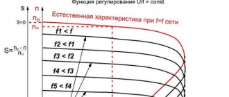
Some converters operating with powerful motors have the ability to quickly switch the operating scheme. This is done in order to expand the range of engine speed adjustment upward from the nominal one. The method is based on the fact that a star connection provides higher torque at low speed, while a delta connection provides higher torque at high speed. You can set the output frequency at which switching occurs, the pause (delay) time for switching, and the motor parameters for the first and second modes.
Frequency converters of this type have outputs for switching on the corresponding contactors, ensuring the formation of the necessary switching circuits.
Inverter settings for star and delta circuits
When choosing a connection scheme, you need to remember that some parameters in the inverter settings are sensitive to the choice of the type of circuit, for example, rated voltage and rated current.
It happens that it is necessary to connect a motor assembled in a delta circuit for a voltage of 220 V to the output of a three-phase inverter, the linear voltage of which at a frequency of 50 Hz is 380 V. It is clear that in this case the motor must be connected to a star, but sometimes this cannot be done.
There is an exit. It is necessary to indicate the rated frequency of the motor is not 50 Hz, as indicated on the nameplate, but 87 Hz (1.73 times more). Similarly, you need to set the maximum output frequency of the converter. As a result of the fact that the V/F ratio at the inverter output remains unchanged, at a frequency of 50 Hz the voltage on the motor windings will be exactly 220 V. In this case, the upper operating frequency of the motor must be set to 50 Hz.
The advantage of this connection is the ability to increase the operating frequency of the engine above 50 Hz, while the engine will not lose operating torque up to 87 Hz. In this case, it is important to monitor the mechanical wear of the system and the heating of the drive.
Other useful materials:
Review of Siemens soft starters Purpose of mains and motor chokes FAQ on electric motors
Triangle connection and its advantages
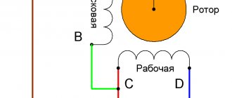
The principle of the “triangle” connection is to connect in series the end of the winding of phase A with the beginning of the winding of phase B. And then, by analogy, the end of one winding with the beginning of another. As a result, the end of the phase C winding closes the electrical circuit, creating an unbroken circuit. This scheme could be called a circle, if not for the mounting structure. The triangle shape is given by the ergonomic placement of the winding connection.
When connected by a “triangle” on each of the windings, there is a linear voltage equal to 220V or 380V.
The main advantages of using the triangle scheme:
- Increasing the power of electrical equipment to the maximum value;
- Using a starting rheostat;
- Increased torque;
- Large traction forces.
Flaws:
- Increased starting current;
- When running for a long time, the engine gets very hot.
The “triangle” method of connecting motor windings is widely used when working with powerful mechanisms and the presence of high starting loads. A large torque is created due to an increase in the self-induction EMF caused by large flowing currents.
Connecting a three-phase motor to a single-phase network using a triangle diagram