What is an asynchronous motor?
Before moving on to the model, algorithms and control systems of an electric drive, you need to know exactly what it is. This makes it possible to identify moments in its circuit that can be used to organize a smooth change in key characteristics (frequency/rotation speed, voltage). Accordingly, it is possible to determine the parameters of the controller, develop technological maps for its placement in the cabinet and maintenance.
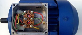
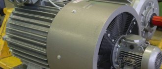
The operation of any asynchronous motor is based on the excitation of a magnetic field on the contact windings when electricity is supplied from the control cabinet. It occurs on the stator - the stationary part of the engine, which consists of a ring core (magnetic core) assembled from individual metal plates. Each of them has concentric grooves on the inside of the ring, which when combined form longitudinal grooves. They are used to wind the wire that forms the basis of the stator winding.
Also, an asynchronous motor has a moving part - a rotor combined with a drive shaft. It also has a plate core with grooves, but on the outside. Instead of wire, copper rods are used, which are closed at the edges by plates (this version of the engine is called a squirrel-cage motor).
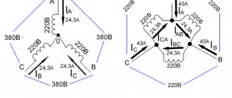
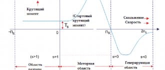
Due to the fact that the rotation frequencies of the magnetic fields of the stator and rotor are different, an electric current is induced in the windings of the latter due to induction. This in turn induces an electromagnetic force that causes the rotor to move (rotate). The frequency difference is usually called glide. Its value is about 2...10%.
Man in a synchronous world
One busy young man had a date planned for the evening. He really wants everything to go perfectly, and for this he needs to do several things:
- deal with working documents;
- pick up a suit from the dry cleaner;
- go to a flower shop for a bouquet of lilies;
- and most importantly, ask mom to make her signature cake.
Without a cake, a bouquet, a suit and a stack of sorted papers, the date will definitely not take place.
A young man lives in a synchronous world. This means that he cannot start the next task until the previous one is completed.
First of all, you need to send a request for the cake, as it takes several hours to prepare. He calls his mom, and she immediately starts kneading the dough. By evening the cake will undoubtedly be ready. However, the young man will not have time to do other things, and the date will not take place. The fact is that he spent all this time with the receiver to his ear, waiting for confirmation that the request was completed. The heartless synchronous world did not allow him to work and buy a bouquet.
Asynchronous programming could solve the problem. With its help, the blocking process of mother's cooking can be removed from the flow of preparation for a date.
In an asynchronous world, a person does not depend on the cake. He asks his mother to call back, and he goes to the dry cleaner to pick up his dress suit. When the last cherry is placed, mom triggers the “Cake is ready” event. A smart young man grabs a bouquet and runs on a date.
How can you control the engine speed?
Obviously, the motor in normal operation from the mains (electrical cabinet) has a standard speed/rotation frequency. This limits its direct use, forcing the use of various gear mechanisms to reduce the frequency to the required one. But even then, there is no way to dynamically change the speed, and with it, power, flow, since the frequencies at the output of the engine and gearbox still remain fixed. To expand the existing framework, different control methods are used (frequency, pulse, phase, etc.), which can be divided into two large groups:
- Scalar. Typically used on drive motors of compressor, fan, pump and other mechanisms where monitoring of rotation speed or any other parameter associated with sensors is required,
- Vector. This is an advanced concept that provides separate, independent control, torque and magnetic flux control. The rotor current coupling is maintained at a constant level, which allows maintaining the maximum torque value.
Asynchronous motor control
The difference between scalar and vector control lies precisely in the possibility of excitation (flow) control. In fact, it is represented as a DC motor having windings independent of each other. This approach allows you to create a similar mathematical model of the controller operating system.
Forms and diagram of vector control
All existing vector engine control systems can be divided into two groups:
- Sensor The engine control unit has speed feedback with it, using the corresponding sensors located on the shaft,
- Sensorless. These are systems that operate without speed sensors on the main shaft.
Sensor systems are more complex, since the control accuracy is 1:10000. Sensorless systems operate at a level of no more than 1:100. All frequency generators, taking into account the level of interference generated, are installed in central or separate cabinets.
If we present all of the above as a visual diagram, we get something like this:
Here you can see such key components of the control system as:
- AD is actually an asynchronous motor (object of control),
- BRP – logical block of regulators for equation variables,
- BVP is a logical block responsible for calculations based on variables,
- BZP is a block that specifies the values of variables,
- DS – speed sensor on the motor shaft,
- AIN PWM – pulse amplitude/pulse width modulation unit.
What is shown in the diagram as blocks is, in practice, just parametric elements of the control circuit, which is implemented on a microcontroller. Accordingly, the controller itself and accompanying actuators are mounted in an electrical cabinet. For proper installation, a technological map is being developed.
Asynchrony Patterns
There are three most popular asynchronous request schemes. Let's look at their implementation using “promises” (JavaScript) and async-await operators (C#).
The demonstration will require test functions that simulate the return of the desired objects with a delay.
JavaScript:
function getPromise(returnValue) { return new Promise((resolve) => { setTimeout(() => { resolve(returnValue); }, 300); }); }
C#:
public static async Task GetStringTask(String toReturn) { await Task.Delay(300); return toReturn; } public static async Task GetIntTask(int toReturn) { await Task.Delay(300); return toReturn; }
Sequential execution
Used for related tasks that need to be run one after another. For example, the first request gets the names of the movies, and the second gets information about them.
JavaScript:
getPromise('value1') .then((result) => { return getPromise(result + 'value2'); }).then((result) => { return getPromise(result + 'value3'); }).then ((result) => { console.log(result); // => value1value2value3 });
Each function returns a new Promise, the execution of which can also be monitored. The result is a convenient single-level chain of promises.
C#:
var str = await GetStringTask("Hello world"); var len = await GetIntTask(str.Length); var res = await GetStringTask("Len: " + len); Console.Out.WriteLine(res);
The str variable will receive a value only when the GetStringTask function has completed. Only after this the code handler will continue execution.
Parallel execution
It is used to solve independent problems when it is important that all requests are executed. For example, web page data is loaded from three servers, and then rendering begins.
Concept in JavaScript:
Promise.all([ promise1, promise2, promise3 ]).then((results) => { … })
The results parameter is an array containing the results of all three performed operations.
C#:
var tasks = new Task[3];
tasks[0] = GetIntTask(1); tasks[1] = GetIntTask(2); tasks[2] = GetIntTask(3); Task.WaitAll(tasks); for (int i = 0; i < 3; i++) { Console.Out.WriteLine("Res " + i + ": " + tasks .Result);
} The WaitAll method of the Task class collects the results of three queries together.
Frequency controller management
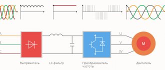
Modern current/voltage frequency converters operate in both scalar and vector versions, using parametric mathematical models implemented in the program code of the built-in microcontroller. Electronic frequency drives operate on thyristor bridge circuits and include the following main components:
- Rectifier - a thyristor or transistor bridge that converts alternating current into direct current,
- An inverter is an AIM/PWM unit that operates on the reverse principle, that is, converting direct current into alternating current.
Since such a transition in one way or another affects the shape of the output voltage graph, the block controller/frequency driver can use special EMC filters in the inductor circuit. The latter are used to reduce the intensity of electromagnetic interference.
Frequency controller management
The central controller provides parametric control of the circuit, as well as auxiliary tasks, for example, condition diagnostics, overload protection, etc. The frequency generator itself is usually mounted in a separate cabinet to reduce electromagnetic interference to the equipment.
In general, vector control, organized on a modern controller and frequency converter, allows for smooth regulation of key quantities, as well as side parameters of equipment operation. Due to the presence of electromagnetic interference during operation, frequency units are usually located separately from the main electrical cabinet.
Control of a three-phase motor in a single-phase network (PS11036, IRPT2060A, IR2130)
In the field of power devices, the “legislators” are the companies INTERNATIONAL RECTIFIER - abbreviated IR and MITSUBISHI Electric - abbreviated ME, as well as INFENION Technologies - IT.
I provide the names of manufacturers so that users can be guided when choosing elements. Since, basically, only these companies are developing the element base for power drives.
This article will help many radio amateurs use modern power electronic devices to control 3-phase electric motors in a single-phase network.
Scheme
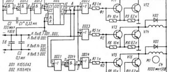
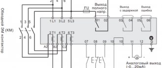
In Fig. Figure 1 shows the electrical circuit diagram of the electronic drive of the electric motor. The device works as follows.
Rice. 1. Scheme for controlling three-phase motors using power electronics in a single-phase network.
The master oscillator DD1 of the NE555 series produces pulses with a frequency of 360 Hz, supplied to pin 9 of DD2 (counting input) 55BTM8 (analogue 74175N - four D-flip-flops). The chip uses three D flip-flops as a shift circuit.
That is, from their direct and inverse outputs a three-phase control voltage with a frequency of 60 Hz comes out, which is supplied to the corresponding inputs of the DA3 IR2130S microcircuit.
In order for the electronic drive to operate at different frequencies, resistor R2 with a nominal value of 100 kOhm must be replaced with a chain of constant 62 kOhm and variable 56 kOhm resistors.
The DA3 IR2130S chip is a six-channel high-voltage driver (control circuit) for controlling output switches from IR. When you press the S1 “Start” button, the driver controls both the upper and lower keys.
Transistors VT1, VT2, VT3 are the upper keys, respectively VT4, VT5, VT6 are the lower keys. The circuit is powered in this way.
Transformer T1 lowers the network voltage to 18 V, which is rectified by bridge VDS2 and filtered by capacitors C3, C6. The rectified voltage is supplied to the DA2 7815 stabilizer.
From output DA2, +15 V voltage serves to power the DA3 IR2130 chip. The +15 V voltage is reduced by the DA1 7805 (KREN5) stabilizer to 5 V, which is necessary to power the DD1, DD2 microcircuits.
Rice. 2. Generator circuit on a microcircuit.
Rice. 3. Installation of an additional resistor.
Rice. 4. Driver circuit.
Attention! The negative wire in the diagram is shown as “In no case should it be connected to the body of the device. It must be securely isolated from the housing. The drive housing itself and the electric motor must be reliably grounded.
When working with the device, be careful to avoid electric shock!
Details
The VDS1 bridge must be designed for a forward current of 20...25 A and a reverse voltage of 400 V. These parameters depend on the power of the motor used. I was counting on a power of 1.5...2 kW.
The bridge KVRS2504 - Ipr is suitable. = 25 A and LJo6p. = 400 V. The used bridge can, of course, be replaced with domestic powerful diodes by installing them on a radiator, but again the dimensions of the circuit will increase.
The VDS2 bridge is designed for Uo6p. = 400 V and Ipr. = 1 A, for example, KTs405. Diodes VD1, VD2, VD3 must be fast-acting, with II converter. at least 400 V, for example 11DF4 or 10DF6.
Resistors R6, R8, R10, R12, R13, R14 with a nominal value of 100 Ohms, R7, R9. R11 - rated 47 Ohms. Protective diodes VD4....VD9 - fast-acting, with II converter. at least 400 V and withstand direct pulse current of more than 30 A, for example, MUR680.
But you can do without protective diodes - for this you need to use output switches VT1 ... VTb with protective diodes built into the transistor housings.
Particular attention should be paid to the output switches VT1...VT6 - these are IGBT technology transistors - a field-effect transistor at the input, i.e. a gate, and at the output a collector and an emitter - this is a first approximation.
That is, IGBT is a mixture of field and bipolar technology. Such transistors are produced by Infineon: BUP311D, BUP313D, Harris: HGTH20N40C1D, IR: IRG8C30D, IRGBC2GD with protective (reverse) diodes.
Fig. 5. Power drive diagram using a MITSUBISHI SEMICONDUCTOR PS11036 module.
All resistors in the circuit have a power of 0.25 W, except R15 - wire-wound (the voltage drop across them should be no more than 0.5 V). The total capacitance of the capacitors after rectifying the mains voltage should be about 1000 µF at a load of 2 kW or more.
The diagram shows the ratings of C7 and C8 of 330 μF each for a load of 1.5 kW. Capacitors C10, C11, C12 with a nominal value of 0.1 μF must necessarily be with low dielectric losses and thermally stable, designed for a voltage of 50 V.
Transformer T1 - power no more than 10 W. If you have difficulties purchasing the DD1 NE555, you can replace it with a multivibrator, assembling it on the domestic 555 series.
The circuit of such a generator is shown in Fig. 2. The clock frequency will be determined by the formula:
F = 1/2C1R1,
Where:
Such a generator will operate in the range 45 Hz ... 25 kHz. If such a wide generation range is not needed, then instead of a variable resistor R1 with a nominal value of 510 Ohms, you need to install a chain of a resistor with a nominal value of 100 Ohms and 470 Ohms (Fig.
3). Output switches VT1….VT6 must be installed on the heat sink through electrically insulating heat-conducting gaskets (mica from large capacitors will do), otherwise the designer will have difficulties with heat removal and electrical insulation.
JR took care of this and developed a wide range of power modules. In particular, for a single-phase network, modules of the types IRPT2060A for a load power of 2.2 kW and IRPT2064A for a load power of 1.5 kW were developed (Fig. 4).
In addition to power switches, the module also contains a power bridge, current-measuring shunts (pins IS1, IS2 and IS3, IS4) for IRPT2060A with a nominal value of 25 mOhm (for IRPT2064A - with a nominal value of 45 mOhm), a thermistor (pins RT1 and RT2), which has a value 50 kOhm ±5% at module temperature 25°C and 3.1 kOhm at 100°C for both modules. The module also has a key installed (terminals BR and N). It is as powerful as six keys and is designed for emergency shutdown of the module.
I didn't experiment with it. All keys are insulated from the module body so that the problem of reliable thermal insulation disappears, although in this case it will not interfere with long-term operation of the module.
In Fig. Figure 5 shows a diagram of a power drive using a MITSUBISHI SEMICONDUCTOR PS11036 module with a power of 2.2 kW. This scheme is the easiest to manage.
True, I could not find modules of this type for a single-phase network. But you can turn it on in the same way as shown in the diagram. Pin FO - alarm signal output.