Calculation of a quenching capacitor for an LED
Let's look at the detailed calculation; below you can find the online calculator form.
Calculation of capacitor capacity for an LED:
C(uF) = 3200 * Isd) / √(Uin² - Uout²)
C µF – capacitance of the condenser. It should be rated at 400-500V; Isd – rated current of the diode (see the passport data); Uin – amplitude network voltage - 320V; Uout – rated LED supply voltage.
You can also find the following formula:
C = (4.45 * I) / (U - Ud)
It is used for low-power loads up to 100 mA and up to 5V.
Calculation of a capacitor for an LED (online calculator):
For clarity, we will calculate several connection diagrams.
Connecting one LED
To calculate the capacity of the condenser we will need:
- Maximum diode current – 0.15A;
- diode supply voltage – 3.5V;
- amplitude voltage of the network - 320V.
For such conditions, the parameters of the condenser are: 1.5 µF, 400 V.
Connecting multiple LEDs
When calculating a capacitor for an LED lamp, it is necessary to take into account that the diodes in it are connected in groups.
- Supply voltage for a daisy chain – Usd * number of LEDs in the chain;
- current strength – Isd * number of parallel chains.
For example, let's take a model with six parallel lines of four series diodes.
Supply voltage – 4 * 3.5V = 14V; Circuit current – 0.15A * 6 = 0.9A;
For this circuit, the condenser parameters are: 9 μF, 400 V.
Overvoltage. Part 1: Long-term exposure to overvoltage
As the voltage applied to an aluminum electrolytic capacitor increases, its internal parts are exposed to increasing electric field strength. If the field strength is high enough, electrical charge transfer through the dielectric layer can occur. This single discharge can increase like an avalanche, causing a so-called partial discharge of the capacitor. This phenomenon is known as "sparking" due to its characteristic sonic appearance. If these partial discharges - at a voltage level typical for a given application of an aluminum electrolytic capacitor - occur too frequently or are of sufficiently large magnitude, they will result in complete breakdown of the dielectric and catastrophic failure of the component. The term "catastrophic failure" refers to a condition of a capacitor where physical signs of damage to its internal parts can be seen.
Definition of test procedure
Due to the delicate nature of partial discharges in the initial region of their occurrence, a unique detector was designed to detect and study this phenomenon. It captures "subtle" microvolt-level capacitor voltage sags (sparking below the audible detection threshold) with a time resolution corresponding to single or slightly avalanche-amplified partial discharges. It also captures the small voltage fluctuations across a capacitor with a time resolution on the order of nanoseconds that characterize the avalanche flashovers that occur. This is shown schematically in Fig. 3.
Rice. 3. Operating principle of the “spark” detector
Discharges can occur on the terminals of an aluminum electrolytic capacitor, current leads, anode and cathode foils and its aluminum body, provided that they are all wetted with electrolyte. Due to a number of theoretical premises and practical considerations, it was decided to select down conductors for a detailed study of the manifestation of partial discharges in aluminum electrolytic capacitors. The current leads were placed in a thermostated vessel with electrolyte and polarized (molded) at a constant current density of 333 μA/cm2.
How does an electrolytic capacitor work?
Inside, such a capacitor consists of two materials with a dielectric (i.e. paper impregnated with electrolyte). These materials are tightly rolled and pressed into an aluminum cup, which is closed with a rubber stopper. The materials are different: one is a metal electrode and the other is an electrolyte. Therefore, it is so important to know the polarity of this capacitor.
The pictures below show a stripped-down 100 µF capacitor :
| Capacitor after removing the housing | Twisted Capacitor Materials | Expanded capacitor materials |
Capacitor Polarity
Polarity: Some capacitors are made in such a way that they can only withstand the applied voltage of one polarity and not the other. This is due to their design: the dielectric is a microscopically thin layer of insulation applied to one of the plates during manufacture using a constant voltage. These are called electrolytic capacitors and their polarity is clearly marked.
Figure 1 – Capacitor polarity
Reversing the polarity of the voltage across an electrolytic capacitor can destroy this ultra-thin dielectric layer, resulting in the destruction of the device. However, the thickness of this dielectric allows extremely high capacitance values to be obtained with a relatively small package size. For the same reason, electrolytic capacitors tend to have low voltage ratings compared to other types of capacitor designs.
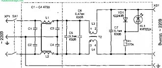
A simple LED power supply circuit with a capacitor
Let's look at a device without a transformer power supply for LEDs using the example of a factory LED lamp driver.
- R1 – 1W resistor, which reduces the significance of voltage drops in the network;
- R2,C2 – the condenser serves as a current limiter, and the resistor is for discharging it after disconnecting from the network;
- C3 – smoothing condenser, to reduce light pulsation;
- R3 - serves to limit voltage drops after conversion, but it is more advisable to install a zener diode instead.
What capacitor can be used for ballast?
Ceramic elements designed for 400-500V are used as quenching capacitors for LEDs. The use of electrolytic (polar) capacitors is prohibited.
Precautionary measures
Transformerless circuits do not have galvanic isolation. The current strength of the circuit when additional resistance appears, for example, touching a bare contact in the circuit with your hand, can increase significantly, causing electrical injury.
Please rate the article. We tried our best:)
Did you like the article? Tell us about her! You will help us a lot :)
