December 23, 2014 Installation of switches admin
Often, when renovating an apartment, it becomes necessary to replace or install a new interior door and at the same time replace light switches.
To install a switch, you must first install an interior door, which can be selected on the website https://www.allwoods.ru/mebel/dveri.html.
It is necessary to give some practical advice that will help you if you are just starting your professional or amateur activity in the field of repair and electrical work.
Practical advice for developing an electrical network project in a house or apartment
The safety and ease of use of household appliances and lighting fixtures depends on the design of the location and wiring of the power line. To correctly calculate the installation height of sockets and switches, you should follow a certain sequence when developing a plan:
- Think in advance about the placement of furniture and electrical appliances around the apartment.
- Make a detailed diagram of each room, taking into account doorways, windows and water and gas wiring.
- On the diagram, mark the location of the sockets, taking into account all recommendations for height and distance between them. Take into account the total power of the required power line, and also add backup points.
- Arrange the switches on the plan depending on the location of the doors and the side of their opening, consider the number of switches in the corridor and the installation height.
Requirements for openings
Installing interior doors requires compliance with certain requirements regarding the preparation of openings and the finished floor (floor covering), so it is advisable to meet with a specialist at the beginning of the repair.
I would like to start with the fact that at the beginning of repair work, you need to clearly determine the location of future doors and their opening. Not only the ease of use of the doors, but also their functionality and interior properties will depend on the correct formation of doorways.
When preparing openings, the following requirements must be observed:
- the opening must be formed (have clear dimensions in height, width and wall thickness);
- on each side of the opening there must be a wall with a minimum size of 80 mm, that is, the opening should not be between two parallel walls and there will be a need to trim the platband along (if the opening does not have walls, you can add a 50x50 beam on each side and this must be taken into account when choosing the width of the door leaf);
- the opening must be decorated in its pure form (plastered, voids filled with plaster, drywall cut off, the inner plane of the opening should not have protruding bricks, foam concrete, no mortar or putty residues), and ideally should also be plastered;
- the thickness of the walls of the opening should be the same along its entire perimeter, and the walls around the opening should form a single plane;
- the planes of the opening walls should not have vertical obstructions;
- the upper part of the opening should be parallel to the finished finished floor, and the finished floor (floor covering) should be as horizontal as possible without differences in height;
- the opening must have the dimensions of a regular rectangle.
Openings for swing doors must correspond to the dimensions according to the table
| Blade dimensions, mm | Opening width, mm | Opening height without threshold/with threshold, mm |
| 600 x 2000 | 680 — 690 | 2060/2080 |
| 700 x 2000 | 780 — 790 | 2060/2080 |
| 800 x 2000 | 880 — 890 | 2060/2080 |
| 900 x 2000 | 980 — 990 | 2060/2080 |
| 600 + 600 x 2000 | 1290 — 1300 | 2060/2080 |
| 700 + 700 x 2000 | 1490 — 1500 | 2060/2080 |
| 800 + 800 x 2000 | 1690 — 1700 | 2060/2080 |
| 900 + 900 x 2000 | 1890 — 1900 | 2060/2080 |
These dimensions are indicated in accordance with the standards, taking into account a 10-20 mm gap for foam around the entire perimeter of the door frame, depending on the thickness of the frame.
If the size of the opening is reduced, foaming the gaps will be difficult, which affects the further use of the doors (the door frame may become loose over time, even taking into account mechanical fasteners around the perimeter of the frame).
If the gaps increase, a large amount of foam can affect the gaps between the box and the canvas in different weather periods, so it is advisable to narrow the opening to the required size. The main danger of non-compliance with the dimensions of the opening is the inability to cover with platbands the gaps obtained after installing the door.
Advice:
When wallpapering, use overlaps.
When laying the finished floor (floor covering) in the area of the opening, minimalism must be observed. The gaps between the wall and the floor covering should be as small as possible, since when installing platbands and extensions, large gaps may remain visible.
Advice:
the junction of two different floor coverings should be located strictly under the door leaf of the installed door.
Installation of swing doors consists of several stages.
The first is inserting fittings (hinges, latches, bolts), installing handles and screws, assembling the box.
The second is installing the box in the finished opening strictly vertically in two planes, hanging the canvas and forming a vestibule.
The rebate is the simultaneous contact of the door plane with the frame seal. The rebate should be on both the hinge side and the latch side. Only in this case will the door fully have soundproofing properties.
It is easy to achieve a vestibule at first glance, but at the same time there are nuances associated with the quality of the prepared opening, the correct insertion of hinges, the curvature of the frame and panels, the quality of the seal and much more.
The rebate in the loop side of the box depends entirely on the correct insertion of the loops, taking into account the difference in the thickness of the canvas and the quarter of the box, taking into account the seal. The porch on the return side allows the door to close softly, without slamming or rattling, with regards to glazed doors.
Simultaneously with the narthex, a gap is formed between the canvas and the box along the entire perimeter of the canvas. The gap should be uniform and should be 2-3mm on the hinge side and 3-4mm on the latch and top side. When using hidden loops, uniformity of the gap can be achieved along the entire perimeter of the canvas. It is important to remember that polyurethane foam (even the professional series) is not stable and can behave unpredictably at different humidity levels. Therefore, the box is secured mechanically with self-tapping screws or dowels, and the areas of possible greatest foam pressure on the box must be wedged. The foam will acquire stable properties in about a day, but the door can be used after 40-60 minutes.
The lower gap is formed depending on the floor coverings, differences in heights of the floor covering in the opening itself and at the place where the door opens, as well as at the request of the customer, but preferably no more than 20 mm.
After foaming the box and drying the foam, the third stage occurs - enclosing the opening with extensions and platbands.
Openings for sliding doors have different dimensions and are shown in the tables below.
For sliding doors to function properly, a lower guide must be installed at the bottom of the door leaf.
Depending on the type of canvas, the lower guides either cut into the bottom of the canvas, or are simply attached to the bottom of the canvas with self-tapping screws. Based on the above, the dimensions of the prepared openings are slightly different.
In addition, you need to immediately decide whether the opening for sliding doors will be decorated with additional trim and platbands or whether the opening will be prepared by builders in its final form (plaster, putty, painting, wallpaper, etc.). The difference in the size of the opening in this case also occurs and is also shown in the tables.
Openings for sliding doors, taking into account the milling of the lower groove for the lower guide, followed by the design of the opening with extensions and platbands
| Single door | Double door | ||
| Blade size, mm | Width x Height, mm | Blade size, mm | Width x Height, mm |
| 600×2000 | 630×2020 | 2x600x2000 | 1230×2020 |
| 700×2000 | 730×2020 | 2x700x2000 | 1430×2020 |
| 800×2000 | 830×2020 | 2x800x2000 | 1630×2020 |
| 900×2000 | 930×2020 | 2x900x2000 | 1830×2020 |
Openings for sliding doors using the bottom guide without milling a groove, followed by decorating the opening with extensions and platbands
| Single door | Double door | ||
| Blade size, mm | Width x Height, mm | Blade size, mm | Width x Height, mm |
| 600×2000 | 630×2035 | 2x600x2000 | 1230×2035 |
| 700×2000 | 730×2035 | 2x700x2000 | 1430×2035 |
| 800×2000 | 830×2035 | 2x800x2000 | 1630×2035 |
| 900×2000 | 930×2035 | 2x900x2000 | 1830×2035 |
If the opening is prepared in its pure form, that is, it is designed by the customer before installing the doors and will not be decorated with additional trim and trim, then it is necessary to adhere to the following dimensions of the opening.
Openings for sliding doors, taking into account milling of the lower groove for the lower guide without opening the opening
| Single door | Double door | ||
| Blade size, mm | Width x Height, mm | Blade size, mm | Width x Height, mm |
| 600×2000 | 560×1985 | 2x600x2000 | 1160×1985 |
| 700×2000 | 660×1985 | 2x700x2000 | 1360×1985 |
| 800×2000 | 760×1985 | 2x800x2000 | 1560×1985 |
| 900×2000 | 860×1985 | 2x900x2000 | 1760×1985 |
Openings for sliding doors using the bottom guide without milling a groove without decorating the opening
| Single door | Double door | ||
| Blade size, mm | Width x Height, mm | Blade size, mm | Width x Height, mm |
| 600×2000 | 560×2000 | 2x600x2000 | 1160×2000 |
| 700×2000 | 660×2000 | 2x700x2000 | 1360×2000 |
| 800×2000 | 760×2000 | 2x800x2000 | 1560×2000 |
| 900×2000 | 860×2000 | 2x900x2000 | 1760×2000 |
Installation of sliding (sliding) doors occurs according to a different scheme
First, the opening is made out (with additions and platbands) in the form of a portal, if the customer has not prepared the finishing opening. Upper rollers are installed on top of the canvas, sliding handles, lower guides and brushes are embedded (for double doors at the request of the customer). The upper guide is attached to the wall strictly horizontally, prepared in advance to size. The canvas is hung and adjusted vertically. We set the bottom gap and the gap between the wall (portal trim) and the canvas and install the bottom roller. Next, we attach the cornice that covers the top guide. We check the free movement of the blades and adjust their extreme positions using clamps.
Convenience and practice: installation tips
Before you begin installing electrical wiring in your home, it is recommended to do the following:
- draw up a diagram showing the location of all the furniture in the room;
- On the diagram, mark the location of household appliances, write down their power;
- mark the places where there is a gas pipeline and water supply;
- mark windows, doors.
Following this scheme, it is worth choosing the most comfortable height of the products. If you do not create an accurate diagram and place electrical outlets at random, some of them may be hidden by massive objects and become unusable.
If, when installing electrical outlets, a part still turns out to be uncomfortable to use, you can use an extension cord.
After completing the installation of power points, it is recommended to carry out voltage measurement work. This will protect the operation of the devices and help extend their service life if a problem is found.
Installing power points and switches in the apartment is the most important point in laying electrical wiring. Fixing at an inconvenient height will not allow maximum use of electrical mechanisms. To select the optimal distance, there are PUE standards; it is also recommended to rely on the size and location of furniture and electrical appliances.
Why are the standards developed?
At first glance, it may seem to an inexperienced person that the standard sizes of doorways are someone’s whim, because it is much easier to make your own exclusive doorway, the size of which was developed for your loved one.
Indeed, no one is stopping you from pushing aside the recommended standard size and doing what you like. But after such a decision you may have a number of troubles, here are just a few of them:
- When you come to the store, you will find a lot of standard doors that will not fit your exclusive opening. Both domestic and foreign manufacturers work in accordance with GOST, otherwise their goods simply will not be sold;
It is much easier to choose a standard model, because absolutely all companies involved in the production of doors produce products that comply with GOST
- Of course, you can go to the nearest carpentry shop, where they will make you any doors to fit any doorways, but the price of a custom-made product will be at least 30% higher than that of serial samples. Plus, someday these doors will have to be replaced and the problem will repeat;
- In addition to the frame and door leaf, the door block also contains a lot of special fittings, such as extensions, trims, locks, etc. So, all this fittings were also developed for a standard opening and it is far from a fact that without additional modification it will become an exclusive model.
Installation height of sockets and switches
The height of switches or sockets in an apartment or house today is not regulated by anything specific. The main principle that should be followed when determining the height at which sockets and switches from the finished floor will be installed is the convenience of their use by you personally.
The generally accepted distances from the floor to electrical installation equipment have constantly changed and, most likely, will change more than once. At different times, in different countries and even regions, this value differed. For example, during the times of the USSR and a little later, the generally accepted installation height of sockets was 800 - 900 mm, and the height of switches was 1500 - 1600 mm from the finished floor to the center of the socket or switch.
Currently, it is generally accepted to install switches at a height of 800 - 900 mm, and sockets 300 - 400 mm, also from their center to the floor of the living space.
Installation height of switches and sockets according to PUE
In accordance with the rules for electrical installations, the installation height of sockets in administrative, office, laboratory, residential and other premises should be convenient for connecting electrical appliances to them, depending on the purpose of the room and interior design, but not higher than 1 meter. PUE, it is also allowed to install sockets on (in) specially adapted skirting boards made of non-flammable plastic.
However, according to the recommendations of the International Consulting Service for the Construction Industry (BICSI), the installation height of sockets depends on the size of the free space in front of it.
Socket installation height table
The table shows that there is some contradiction in the numbers between the recommendations of the PUE and BICSI, however, the installation height of sockets 300 - 400 mm, and switches 800 - 900 mm from their center to the floor, can be considered generally accepted.
Separate cases of choosing the height of installation of sockets
There are cases when the above recommendations are not suitable for the convenient use of sockets, for example, near desks they should be placed a little higher than the tabletop, at a height of approximately 800 mm from the floor level. Sockets near kitchen tables should be placed even higher, at a height of approximately 1050 mm from the floor. In the bathroom, the installation height of the socket can reach 1800 mm.
Installation height of sockets and switches
It is best to place switches immediately at the entrance to the room. It is advisable to do this so that in all rooms they are on the same side, of course, if it is possible to do this. Switches should be positioned so that an open entrance door does not block access to them. The distance from the door frame to the switch should not be less than 100 mm. In the bedroom it is very convenient to use walk-through switches, which can be placed above the head of the bed or above the bedside table.
Existing standards
The current rules for the construction of electrical installations (PUE) and the set of rules for the design of residential and public buildings (from 2003) do not describe the exact requirements for the location of sockets or switches relative to the floor, walls, furniture and other structural and interior elements.
However, there are still some requirements due to the need to ensure fire and electrical safety. They usually relate to the placement of switches at a safe distance from other communications. According to the set of rules for the design of residential and public buildings:
- switches should be located at a height of 1 meter from the floor on the side of the door handles;
- a distance of 1 meter must be maintained from the floor to the outlet, but the specific location is not regulated.
The PUE prescribes the following recommendations when designing the electrical network in an apartment:
- the location of the switch is similar - 1 m from the floor from the side of the door handle;
- if there is a dedicated switch to the comfort control level, the switch can be installed under the ceiling;
- when placing sockets and switches in the kitchen, they should be kept at a distance of at least 50 cm from gas pipelines and appliances;
- in the bathroom, toilet and kitchen, these electrical devices must be located at a distance of at least 60 cm from both the floor and plumbing equipment.
For many years now, in our country there has been such a thing as a European standard for the placement of electrical components. It is believed that according to the European standard, sockets should be located at a height of 30 cm from the floor, and switches - 90 cm from the floor. In reality, there is no standard - it is just a symbol. This method of wiring electrical components received the definition of “Euro” during the spread of another controversial definition - European-quality repair. In part, the European standard was given its name due to its opposition to Soviet norms. According to Soviet standards, switches were placed at shoulder or head level (approximately 160 cm from the floor), and sockets were placed at a height of 90-100 cm.
Ground switch
Despite the apparent absurdity, there are such models. In general, the grounding loop should not have disconnecting devices along its entire length. Therefore, the contacts of the switch with grounding do not intersect. Metal parts of the housing may be grounded: for example, the mounting substrate is often made of steel for strength. When installing internal switches in the bathroom (which is generally undesirable), or in places where moisture could potentially get on the housing, protective grounding is used. If a dangerous potential of 220 volts occurs on the housing and a wet wall, a short circuit or current leakage will occur. The circuit breaker or RCD will trip.
Useful tips
Despite existing standards, many homeowners prefer to do “whatever is convenient for them.” To prevent non-standard solutions from causing undesirable consequences, you should familiarize yourself with a few tips:
- It is recommended to schematically depict sockets and switches on the surface of the walls; this will allow you to analyze convenience and practicality.
- For safety reasons, do not install switches near sources of moisture or heat.
- Even at the stage of repair work, you need to decide where the furniture will stand, otherwise it may block access to electrical points.
You can consult with your relatives and friends; perhaps many of them have already made repairs a long time ago and they have something to compare with and what to advise.
How to install a light switch
The first thing you need to do is turn off the breaker. Some people believe that it is safe to turn off only the meter on which you install the switch, but we strongly recommend that you keep the main power supply switch turned off.
Turn off the machine
Then, use a voltage tester on each wire to make sure there is no electricity and everything is safe. We emphasize that it is better to check this several times before touching the electrical wires.
Switch connection wiring
The next step of the project is to remove any paint, residue or dirt from the box using pliers. Make sure that the area under the switch is free of debris and excess materials. This operation is important, especially if you are dealing with a newly built house or a repainted room.
However, even if you are replacing the old switch, you need to make sure that the new electric light switch will be installed and aligned properly.
Electric switch
After you have purchased the light switch, you must open it using a screwdriver. This operation is important because you will connect the electrical wires to the inside of the switch.
The next step of the project, after we have opened the light switch, we need to start connecting the switch. Use pliers to cut off excess wires approximately 6 inches from the wall.
Shortening the wires
This length should be enough to connect the switch, and it should be more convenient to operate. Remember that you should not leave long wires; in the future they may not fit into the switch box.
Once we've made sure the wires are cut to the proper length, we continue to the next step. Use pliers to remove approximately 2.5 cm of wire insulation. Remember, to avoid touching the exposed wire in the future, do not chamfer more than the specified length.
We strip the wire for connection
Mini-revolution in automation: Honeywell wireless limit switches
The presentation of the new line of Limitless wireless limit switches from Honeywell begins with the slogan: “Imagine a world without wires...”. The idea of eliminating wires from the process has been in the minds of engineers and technologists for decades, however, despite some progress in this area, wired connections are still extremely widely used in both industrial and consumer electronics. What is the reason? To understand this, it is necessary to consider the strengths and weaknesses of wireless technologies.
Pros:
- Flexibility of configuration;
- Space saving;
- No need for wiring;
- Impossibility of tears, cuts;
- Durability.
Minuses:
- Additional difficulties (need to set up, require separate power supply);
- High price.
It would seem that such a few disadvantages should not become an obstacle to the implementation of wireless technologies, but excessive complexity and cost often stop even very promising developments. Honeywell engineers have focused their efforts on making connection and setup as simple and fast as possible, and at the lowest possible cost.
The maximum distance between the transmitter (Limitless WGLA (Figure 1) or WLS (Figure 2)) and the receiver ( WPMM Monitor ) can be up to 1000 feet (over 300 m).
Rice. 1. Limitless limit switch WGLA series
Rice. 2. Limitless limit switch WLS series
Radio transmission uses the widely accepted IEEE 802.15.4 standard, which describes the physical layer (PHY) and access mechanism layer (MAC) for private wireless networks (WPAN). 's XBee radio modems are used as the base control board in the switches , and, accordingly, ZigBee is used as the high-level transmission standard . The devices operate in the free 2.4 GHz frequency range, which makes their use cheaper due to the absence of license fees.
To get started, you need to have at least one pair connected to each other: a transmitter - a wireless limit switch (they are available in two different series: WGLA - for standard applications and WLS - for working in harsh conditions) and a receiver - it is called a monitor (wireless panel -mount monitor - WPMM). When the transmitter contacts are closed, the monitor can produce a sound and light signal, plus control the device connected to its output (a normally open NPN output is used).
In the bedroom
In bedrooms, children's and other rooms, switches and sockets should be located based on their need in specific places and comfort of use. A “classical” scheme is considered when paired installations of a socket + switch are installed on both sides of the double bed. This makes it easy to connect low-power devices (charge your phone, for example) and easily adjust the lighting. Devices can be at the same or different heights
Please note that at a small height (about 30 cm from the floor) you need to place a socket for the vacuum cleaner - from this place its cord should easily stretch in any direction. The power source for computer equipment should, accordingly, be located near the desktop, given that one outlet will not be enough for it
In all cases, the main guidelines in choosing the location of devices are safety and comfort. The second, perhaps, can sometimes be sacrificed in favor of design, but the first factor is always of key importance.
The difference between Soviet and European standards
Despite the lack of documented definitions, the concepts of “Soviet” and “European standard” are widely used among builders and electricians, since with their help it is easy to accurately describe the difference between both methods of placing sockets and switches. At the same time, it cannot be categorically stated that one of them is more preferable - it all depends on individual operational and practical features.
Eurostandard:
- convenient lighting control is provided, since there is no need to raise your hand to press the switch, it is easy to feel in the dark, this arrangement is also convenient for children and teenagers;
- according to the European standard, you have to bend down almost to the floor to plug the device into the outlet - this is inconvenient if you need to turn it on and off frequently; in turn, when the device is connected to the network for a long time, this is a plus - the wires do not “hang” in the middle of the room and do not spoil the appearance of the room.
"Soviet" standard:
- placing the switch at a level of 160 cm from the floor makes sense if you need to save space - furniture can be placed under it against the wall;
- a socket located at a height of 1 meter allows you to use it constantly without difficulty, which is important for a washing machine, vacuum cleaner, microwave oven, toaster, air conditioner and other appliances that are not connected to the network for a long time;
- An additional advantage of high placement of sockets is the safety of small children.
How to position light switches correctly?
Switches on the scale of repairs are such a small thing! But their correct location can make everyday life much more comfortable and convenient. We’ll find out exactly how below.
It is best to place switches at a distance of 10-15 cm from the doorway. When entering any living space, a person intuitively tries to find the switch on the wall next to the entrance.
Photo: Nicole Marino
The optimal height for the switch is 80-90 cm from the floor level. Of course, as many remember, the Soviet renovation, which involved installing a switch at head level, did not make life much more difficult for anyone - even children perceived it as a peak that needed to be conquered. But still, the height at which the switch can be felt with your hand without lifting it is much more comfortable and ergonomic. That is why in families where the height of adults is below average, it is more correct to install switches not even in accordance with the new generally accepted standards, but even lower to the floor.
More about comfort: this is not very obvious, but it is really more convenient if the light is turned on by pressing the upper part of the key, and turned off by pressing the lower part (provided that the switch is not a pass-through or rocker switch)
To understand why, pay attention to how you hold your hand when you enter a room and need to turn on the light, and how you hold your hand when you leave and need to turn it off. Are you sure?
Whatever position of the key the light turns on in the end, make sure that this is the case in all rooms. That is, if you need to press the top of the key to turn on the light in the kitchen, it should turn on in the same way in the nursery, bathroom and living room.
Photo: Aleksey Gnilenkov
The switch should be located on the same side as the door handle. So that you can open the door with one hand and turn off the light with the other.
If there are several light sources in the room at once (which is in accordance with the rules), let each of them have one switch with one key, rather than one switch with several keys. This rule is due to simple convenience - sometimes hitting a key without hitting others can be quite problematic.
It is not necessary to “attach” one lighting fixture to one switch. You can group different light sources and connect them to a single switch. For example, one may be responsible for soft light (floor lamps, sconces, backlights), the other for bright light. Each of these light scenarios is suitable for different life situations. For example, on an early winter morning, a stream of bright light will only irritate, but by the afternoon of a winter day, when the lack of natural light is especially noticeable, such light will come in handy.
Switches for the bathroom, as well as other rooms without natural light (pantry, dressing room, etc.), should be located outside them, for example, in the hallway.
If you decide to install the bathroom switch in the room itself, make sure that the distance from it to the door of the shower or bathtub is at least 70 cm.
Switches in the kitchen should be at some distance from the sink and gas pipe - 50-60 cm from them.
Photo: Emily May
If there is a sconce hanging above the bed in the bedroom (although designers recommend choosing bedside rather than wall lamps, which only illuminate the top of your head during evening reading), it is better to place its switch 10 cm above the bedside table.
Photo: Wicker Paradise
If the bed is double and there are also two sconces, you can place the switches above the bed in the middle (so that everyone has access to their own light) and add a pass-through main light switch to the panel. Pressing it is much more convenient than getting out of bed and trudge to the exit to turn off the main light. The only thing that needs to be taken into account with this arrangement is that the two extreme switches are responsible for the sconces, and the one in the middle is responsible for the “big” light. This is necessary in order not to get confused which of the switches regulates the operation of the main lamp, and which of the additional ones.
If the bed is double and there are also two lamps above it, do not make only one switch on them. For someone who wants to sleep rather than read, it will be much more comfortable if the light is not on over his “half”.
Where should the switch be placed?
The location of the switch depends on the purpose of the room. In any case, for main lighting it is installed immediately next to the front door on the handle side. You should not place the switch behind an open door, as this will complicate its operation and lead to accidental presses.
Also, it should not be partially or completely covered by furniture and interior items. The installation height of the switch should be comfortable for all family members, both adults and children. To make it comfortable to press the key, consider the average height of the hand lowered down for all adult family members.
Possible faults
If after installation the light bulb does not light up, then it is possible that the wires are poorly twisted. You need to check the connections. To do this, there is no need to check each one. You need to start with the wires entering the switch. We take an indicator screwdriver and check whether electricity is supplied to the switch. Using a screwdriver, touch the ends of the wire entering the switch one by one. If the indicator is not lit, then there is a problem with the connection to the public network. Once again we twist the wires connecting the operating phases of the switch and the general network, having first turned off the power. Let's check again.
If current is supplied, but the light bulb still does not light, then the fault is either in the switch or in the rest of the electrical circuit. If the switch is working properly, the indicator should light up when you touch both of its contacts. If the indicator lights up on only one of the contacts, then the switch is faulty. It's better to replace it immediately. A defective item will not last long. If the switch is working properly, we check each connection until we find the fault.
Existing European standards: is there such a concept?
The terminology “Eurostandard” began to be used together with the concept of “European-quality renovation”. In fact, there is no such term, because each European country uses its own standards for the location of food outlets. The European standard means the following values: the installation height of switches from the floor should be 90 cm, sockets - 30 cm. This arrangement can be comfortable for children who can independently reach the switch and turn off the light.
At what distance from the interior door should a light switch be installed?
Often, when renovating an apartment, it becomes necessary to replace or install a new interior door and at the same time replace light switches.
To install a switch, you must first install an interior door, which can be selected on the website https://www.allwoods.ru/mebel/dveri.html.
It is necessary to give some practical advice that will help you if you are just starting your professional or amateur activity in the field of repair and electrical work.
Where to start installing a door?
The first thing you need to do when installing a door is to prepare all the necessary tools and materials.
Door installation begins with the installation of the frame. Typically, doors from the manufacturer come complete with a door leaf, especially if they are made to order. Therefore, the box is completely inserted into the opening between the rooms.
Wooden wedges are placed on the sides and top, and the door in the opening is adjusted according to the level. When the door is completely installed, holes are drilled through the artsabs in two places (bottom and top).
After drilling the hole, the anchor dowels are inserted and the bolts are screwed in. All that remains is to foam the distances between the walls and the frame around the entire perimeter with foam. After it has dried, cut off the remaining dry foam that has protruded beyond the doorway.
After the door is completely installed, trims are attached to one and the other side of the door. The door is fully installed.
Switch installation
When the door is installed, you need to move on to the issue of installing the switch.
Here some may say that it makes no difference where the switch is installed. But this is not so, because there are generally accepted domestic and international standards according to which the regulatory distance is determined.
Light switches can be installed at the following distances:
- According to domestic rules, it is recommended to install the switch at a distance of 160 cm from the floor surface. This regulation is explained by the fact that such a distance is safe in the context of children’s access to electrical elements of the house.
- International rules state that switches must be installed at a distance of 90 cm from the floor level. Many experts think so. This is the most practical distance, since it is possible to turn off the lights faster even for short people.
The generally accepted regulatory distance for installing a switch is 15-20 cm from the door frame on the handle side for opening doors indoors. For the kitchen and bathrooms, it is recommended to move the switch outside the room and install it in front of the doors.
Based on materials: https://www.allwoods.ru/mebel/dveri.html
Forming gaps in interior doors: determining the size and making your own
Author of the article: Alexandra Ivanova December 29, 2020
- Standard Requirements for Door Clearances
- Consequences of incorrect installation
- Stages of installing an interior door
- Formation of gaps
- Eliminating a large gap
- Increasing the lumen
Precisely selected gaps when installing interior doors are the key to durability and proper operation of the structure. The installation of doors is regulated by relevant requirements. One of them is the presence of gaps, thanks to which the leaf closes and opens freely, even if the material swells or the door is slightly skewed. Read the article on how to make gaps.
Standard Requirements for Door Clearances
Alignment of the door structure vertically and horizontally during installation is carried out using a spirit level. It is advisable to entrust the process to a professional with experience, knowledge, and tools. The work seems simple, but it requires precise calculations, accuracy and responsibility, and an understanding of the properties of materials. Poor installation can be identified by the following “diseases” of the new door:
- the canvas swings open and closes on its own;
- the door does not fit tightly to the frame;
- the box itself is a little skewed;
- the canvas rubs against the box, removing the top layer of material.
If installation errors are initially unnoticeable, then over time, when the structure begins to deform or scratch the floor or frame, there will be no doubt about the poor quality of the gaps.
There are recommended distances between the doors and the frame and the floor. If all requirements are met, the result will be impeccable.
Between the door and frame
The dimensions of the gaps between the door leaf and the frame vary depending on the height, width and weight of the door.
The standard gap size is 6 mm. Please allow 1mm error. For doors of standard dimensions (200x60x90 cm), gaps of 5 mm are recommended, no more. If we are talking about a room where the humidity level is high, leave a gap of up to 7 cm. Wooden doors swell from dampness, steam and high temperature. This factor must be taken into account when installing doors in the bathroom and kitchen.
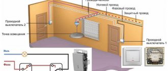
INSTALLATION AND LAYING OF WIRES
Installation methods vary depending on the material of the walls and ceiling. Wires can be laid:
- in grooves (for plastered walls) – hidden installation of electrical wiring;
- in a corrugated protective pipe (for walls and partitions made of plasterboard sheets);
- in a cable channel - for installing open electrical wiring on flammable surfaces - wood or plastic.
Installation of electrical wiring in boxes is convenient because it requires minimal effort when replacing or repairing the cable.
Electrical wiring requires compliance with the following conditions:
- horizontal sections of the laying should be spaced from the ceiling or floor level at a distance of 150 - 200 mm;
- vertical sections - at a distance of at least 100 mm from corners, door and window openings;
- outlets for connecting sockets, switches, lighting fixtures - strictly at right angles to the main wiring.
The desire to save money and lay the wire along the nearest path will lead to the fact that after a while, when drilling a hole in the wall for a picture or cornice, the drill will stumble upon the wire. It will also be difficult to find the faulty section of electrical wiring.
The diameter of the pipe must be selected in such a way that it is possible, if necessary, to replace the cable without resorting to major repairs.
Electrical wiring along the ceiling is carried out either in grooves or in technological holes in concrete floors. If there is a suspended or suspended ceiling, the wire is laid in the interceiling space in a corrugated hose.
The ends of the cable coming out at the installation sites of sockets, switches and distribution boxes must have the required length margin. When installing hidden electrical wiring in grooves, the cable is secured with special brackets.
ELECTRICAL WIRING IN THE FLOOR
Installing electrical wiring in the floor has its own characteristics. It is beneficial at the stage of performing rough repair or construction work and can reduce the cost of purchasing wires, since the requirements for the location of the cable here are not as strict as for wall or ceiling installations.
The following conditions must be met:
- use of protective corrugated pipe;
- the thickness of the concrete screed on top of the wires is at least 30 mm.
Electrical wiring on the floor must be carefully thought out, since it will be impossible to redo it later.
INSTALLATION OF DISTRIBUTION BOXES
Distribution boxes are used for making taps and branches of electrical wiring. Distribution boxes are installed in places where lines for sockets, switches, and lighting fixtures are branched off.
Wire connections in boxes are made using special connecting terminals, twisting or soldering. The last method is the most reliable, but also the most labor-intensive, since it requires the use of special tools and materials.
Wire connections in junction boxes are insulated using insulating caps, bushings or, in extreme cases, fabric insulating tape.
SELECTION OF PROTECTION MACHINES
To protect against short circuits on the electrical panel, circuit breakers are installed in each circuit, which open the circuit when the specified current is exceeded.
To reduce the risk of electric shock when electrical appliances are damaged in rooms with high humidity - bathrooms, kitchens, residual current devices (RCDs) are used, which also open the circuit when leakage currents occur, for example, when the heating element in a washing machine or kettle is damaged.
After all work is completed, the electrical wiring installation diagram is adjusted, since in most cases, the original diagram will change due to factors not taken into account during the design.
ERRORS IN ELECTRICAL WIRING
Common mistakes to avoid that can lead to accidents:
- for any installation options, conductors should not be allowed to intersect;
- Direct connection of aluminum and copper conductors is not allowed;
- The use of plastic electrical tape in junction boxes is not permitted.
Circuit breakers should not have too much current reserve, but weak circuit breakers can cause false network shutdowns, for example, when several loads are switched on.
RCDs are selected according to the permissible leakage current. Incorrectly selected parameters will also cause false alarms or, conversely, lead to electric shock if the selected margin is large.
* * *
2014-2020 All rights reserved. The site materials are for informational purposes only and cannot be used as guidelines or regulatory documents.
Modular circuit breakers
To clarify the characteristics, use the filter.
We offer modular KEAZ automatic machines on favorable terms - directly from the manufacturer. These devices make it possible to implement effective solutions in various areas of energy supply.
The range includes two types of models:
- Automatic devices of the OptiDin BM63, BM125 series are designed to build comprehensive solutions for the protection and distribution of electrical energy in industry, commercial, civil and cottage construction. A large selection of DIN rail models allows you to choose the best option for power supply to residential buildings, public institutions, commercial facilities or infrastructure facilities. These include machines that are used with innovative snap-on accessories.
- OptiDin modular machines are certified for compliance with household and industrial GOSTs, comply with the requirements of river and sea registers, and are licensed for installation at nuclear power plants.
- Modular automatic machines of the VA47-29, VA47-100 and VN-32 series are certified for compliance with GOST. They are designed to meet the needs for high-quality and affordable electrical equipment for the budget and social construction segment.
Products are manufactured by KEAZ in a full cycle: from the development of design documentation to assembly and after-sales service.
Advantages
Their characteristics and prices depend on the series of modular machines.
Main advantages of OptiDin circuit breakers:
- increased wear resistance due to silver-containing soldering on the moving contact;
- accessories are fixed with a latch - a guarantee of reliable connection in 1 click;
- safe shutdown in case of an accident due to the presence of 13 plates in the arc chute;
- the ability to seal terminal blocks to prevent unauthorized connection of power supply lines;
- efficient cooling - profile recesses are provided on the body;
- prevention of heating and melting of conductors, which is ensured by the special design of the clamps.
Automatic switches of the VA47-29, VA47-100 and VN-32 lines have the following features:
- The contact terminals are notched. This ensures tight contact, increases connection strength and reduces contact resistance. The connected conductors are guaranteed not to overheat or melt.
- You can tighten the screws on the terminal clamps to the required force using any shaped screwdriver - the screw head has a combination slot.
- Comprehensive protection of electrical equipment and networks against overload and short circuits.
- Wide possibilities for the layout of panels - modular devices can be mounted vertically or at right angles.
- There is an indicator on the front panel that allows you to control the position of the main contacts regardless of the position of the control handle.
- Possibility of operation at temperatures from –60 to +40 °C.
- Affordable price - models of these lines belong to the budget segment.
Selection Guide
KEAZ produces various types of modular circuit breakers. Among them are models with different numbers of poles, rated currents, and type of protective characteristics.
The most affordable machines can be found in the BA47-29 line. They are designed for rated currents from 1 to 63 A, the maximum breaking capacity is 4500 A. The degree of protection is IP20.
For circuit breakers of the BA47-100 series, rated currents are in the range of 16-100 A, the maximum breaking capacity is 10,000 A. Dust and moisture protection - IP20.