To perform basic electrical work, it is absolutely not necessary to call a specialist. Knowing how to connect an LED switch, you can install it yourself. Agree, this skill will be especially useful if there are major repairs and updating of electrical wiring.
We will tell you about the connection diagram, installation method and difficulties that may arise during installation. You can also improve an ordinary switch with your own hands by making it backlit.
How a backlit switch works and works
We will describe the design of an LED switch using the example of a two-key backlit device.
The mechanism consists of the following elements:
- one input, two output terminals;
- current limiting resistor;
- moving contacts.
The design also includes a housing, a decorative panel and key pads.
Some models of backlit switches have a ready-made connected backlight mechanism. They also produce models in which the backlight conductors need to be connected to the terminals independently.
When the contacts of the LED switch open, the current flowing through the phase wire flows to the resistor, then to the LED or neon lamp. Next, the voltage passes through the lighting fixture and exits through zero.
Since the backlight is connected through a current-limiting resistor, the voltage in the network decreases and is enough for illumination, but not enough for the chandelier to operate.
This is how an LED switch works. If the lighting lamp burns out or is unscrewed, the circuit will be open and the backlight in the device will not work (+)
After the switch contacts close, the current, which always moves along the circuit with the least resistance, passes through the network that powers the lighting lamp - in this circuit the voltage is practically zero. The current also flows to the backlight circuit, but it is so small that it is not enough even to operate a neon lamp.
The circuit includes a current-limiting resistor and an LED or neon lamp. Otherwise, the design and connection method are the same as for a conventional device (+)
Preparatory stage
If you have not encountered replacing or installing backlit switches before, you will have to prepare a little and think through your actions. In general, measures to remove a neon light bulb or LED can be divided into two stages:
- removing voltage from live wires;
- preparation of the necessary tools.
The first point is to de-energize the room in which the illuminated switch is located. To do this, the circuit breaker handle must be moved to the “off” position. In some houses, instead of them, fuses (plugs) are installed, which will have to be unscrewed. If the phase and neutral wires are connected to different machines, then for complete safety, turn off both machines (remove both plugs).
The essence of the second stage is to avoid unnecessary fuss in search of the missing tool during work. To remove the backlit switch and turn off the backlight, you will need: an indicator screwdriver, a heavy-duty flathead screwdriver, wire cutters and a knife.
Application of LED Switch
A backlit switch is installed where it is dark even during the daytime, and constant use of the lighting device is impractical. It is also used in rooms where access is required at night.
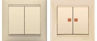
A switch with LED backlight, just like a regular one, can be solid-body or consist of one, two or more keys
The more light sources, the more keys on the switch will be required. To control lighting consisting of more than three lighting fixtures, dial switches are used, which are installed in one row.
To control lighting from several places, purchase a special backlit switch.
Preparing to connect
An illuminated switch is connected to the network in the same way as a regular one. The additional circuit does not affect the main functions of the two-gang switch. A phase wire is connected to the device itself. This allows you to avoid voltage appearing on the lamp socket when the device is turned off. Neutral wires, on the contrary, are connected directly to the lighting fixture. Before starting work, the electrical network must be de-energized by turning off the machine or unscrewing the safety plugs.
First, you should disassemble the switch to become familiar with its design. Disassembly begins with the keys secured with pins or plastic latches. Usually, they are pulled out with little effort, one by one - first one, and then the other.
After the keys, the body is freed from the decorative frame. It is secured with two screws that can be easily unscrewed. When all plastic parts are removed, the electrical part of the device is completely exposed to view. You immediately need to determine the location of the terminals where the wires will be connected. The terminals themselves are equipped in the form of small copper pads with clamping screws. The wire is cleared of insulation, inserted into place and pressed with a screw.
If there is a backlight, you need to strip the wire and insert it into the desired spring connector. The internal spring simultaneously provides reliable fixation and high-quality contact.
How to choose an LED switch
When buying an LED switch, there is no need to chase expensive ceramic devices, since the power consumption of lighting devices is generally not very large.
For domestic use, it will be sufficient to use a high-quality plastic LED switch with a reliable contact group. The service life of such devices is about 40,000 switchings.
For hotel rooms, illuminated switches are used, which are controlled using a key card. They can be with or without a shutdown time delay
The choice is also made based on the design of the device, the type of inclusion - they produce keyboard and rotary, push-button, touch and cord.
Depending on the installation method, internal and external devices are distinguished. The case material can also be different - plastic, glass, copper, stainless steel are used, and slate, gold plated and even leather are used as decorative coatings.
But what you really need to pay attention to is the protection class (IP) - it indicates the possibility of using the equipment in certain conditions.
For example:
- An IP class of 20 indicates that the device is poorly protected from dust and moisture. Such equipment is used in residential premises.
- Class IP 45 and higher is used for marking switches suitable for connection in rooms with high humidity - baths, saunas, kitchens, toilets, etc.
- An IP class of 65 means that the switch can be used outdoors. Such electrical equipment has increased protection from dust and moisture. Installed outside the building - under the porch, canopy, on covered verandas. It has more massive keys, and at the point where the electrical wire enters there is a rubber seal.
The higher the class, the more protected the device is from external factors. This applies not only to switches, but also to sockets, toggle switches, and other electrical equipment.
Connection methods
Connecting the LED strip to the power supply in series
Therefore, we pay attention to the polarity: we connect “+” only to the same pole, and “-” to the minus
At the end of the tape that comes on a reel, conductors are soldered. If the glow is monochrome, there are two conductors - “+” and “-“, for multi-color ones there are 4, - one common “positive” (+V) and three colored ones (R - red, G - green, B - blue).
Bobbins in their purest form
But a 5-meter piece is not always needed. shorter lengths are often required. Cut the tape along the marked lines.
Cutting lines on LED strips
In the photo you see contact pads on both sides of the cut line. They are labeled on each tape, so it’s quite difficult to get confused when connecting. To make it even easier, use wires of different colors. It will be clearer this way and you definitely won’t get confused.
Connectors
You can connect the LED strip without soldering. There are special connectors for this. These are specially designed devices - plastic housings that ensure proper contact. There are connectors:
- for connecting conductors to the strip;
- connection of two tapes. Different types of connectors
Everything is very simple: open the lid, insert a tape or conductors with bare ends. The lid closes. The connection is ready.
The method is very simple, but not very reliable. Contact is ensured only by pressure, and if the cap is loosened a little, problems begin.
Soldering
If you have any soldering skills, it is better to use this method. To work, you will need a soldering iron of medium power, with a thin or sharpened tip. You need rosin or flux, as well as tin or solder.
We strip the ends of the conductors from insulation and twist them into a tight bundle. We take a heated soldering iron, lay the conductor on the rosin, and warm it up. We take a little solder onto the soldering iron tip and warm up the wires again. The veins should be covered with tin - tinned. In this form, the conductors are easy to solder.
How to connect a diode strip
It is advisable to tin the contact pads in the same way: dip the soldering iron in rosin and warm up the pad. Make sure that tin does not leak beyond the pads. Take the prepared conductor, place it on the pad, and heat it with a soldering iron. The tin should melt and tighten the conductor. Hold the conductor in place for 10-20 seconds (sometimes it’s easier to hold it with thin-nose pliers or tweezers - the conductor gets hot), tug. He must hold on tight. Similarly, we solder all the necessary conductors.
On RGB strips with 4 wires, make sure that the pads do not connect during soldering. The distance between the contacts is very small, the slightest drip can ruin the whole thing. Proceed carefully.
Watch the process of soldering the diode strip in the video. You will need to repeat everything.
How to carry out installation correctly
The illuminated switch mechanism involves a small lamp that glows when the switch is turned off. A small neon lamp or LED along with a resistance element can be used to illuminate the device. The backlight has wires that need to be connected to power during installation.
Preparing for installation and mandatory safety precautions
Without basic knowledge of safety precautions, it is better not to start working with electrical equipment at all. Illiterate electrical installation can lead to electric shock, failure of electrical appliances, and fire.
Basic rules of behavior when working with electricity:
- all work must be carried out in a de-energized network;
- it is unacceptable to overload the power grid;
- check the markings of the wires for compliance with the connected network;
- It is better to replace a damaged section of the network rather than repair it;
- Do not touch connected equipment with wet hands.
A regular indicator screwdriver or multimeter will help determine the nature of the conductors - where is the zero and where is the phase. The indicator is sufficient if the electrical network is single-phase. To analyze a three-phase network, use a multimeter.
Bringing one of the multimeter tentacles to the phase, the other is fixed on any of the conductors. The range for alternating current is set to 220 W. Zero upon contact will show a value of about 220 W, grounding is always lower
Installation example of a 2-gang switch with backlight
The main design differences between LED switches are in the backlight mechanism. It can be ready to use and does not require any action to connect it. Another type of design requires connecting wires that power an LED or neon lamp.
Let's consider a more complex option - how to connect a backlit device, in which the conductors need to be connected independently.
A design feature that allows easy access to the backlight wires can be useful if you need to turn it off
First of all, pry up the keys with a screwdriver or other suitable tool and remove them. Separate the core (internal mechanism) from the body.
Next, determine the correct position of the switch using an indicator. To do this, by touching the contacts with a screwdriver on one side and an indicator on the other, check whether the device is on or off.
If the indicator lights up, it means it is turned on. In this state, turn it so that the keys with the pressed side are located on top.
For a regular indicator screwdriver to work, you need to hold it correctly - the metal part must touch the contact plate, and the top must be touched with your thumb
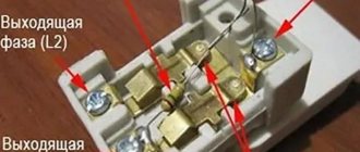
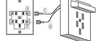
One of the wires coming from the indicator is connected to the input terminal, and the second is connected to the key contact. If there are several keys, then the wire is connected to the first of them, starting from the left. Simultaneously with the wire going from the indicator to the input terminal, the phase conductor is also connected.
The two outlet phase wires that go to the chandelier are connected to the output terminals simultaneously with the second backlight wire, making sure that it does not fall out of contact.
With this connection method, the backlight will turn on after opening the contacts using the first key. The second will not have any effect on turning off the backlight, and the light will remain on even when the lighting is on.
In order for the indicator light to go out when you press any of the keys, you need to make a jumper yourself that will connect the indicator to both keys.
If you do not take into account the connection of the backlight, installation proceeds as in a conventional device. A phase conductor is led through the junction box to the switch and connected to the input terminal L, inserting it into the hole and screwing it in with a screw.
Next, two outlet phase wires are connected to the device contacts L1 and L2, which also lead to the chandelier through the junction box. One of them is connected to one lamp, the other to the other two. The zero passes through the junction box in the wiring box, then goes to all the chandelier lamps, closing the contact.
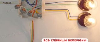
As a result of correct connection, the first key will turn on one lamp, the second two, and two turned on keys will lead to the activation of the entire lighting device. When switched off, the LED (+) should light up.
The remodeling process is accessible to everyone!
From the outside, a pass-through switch is the same as a regular one; it can have one, two or more keys. Moreover, a regular switch can be converted into a walk-through one. The difference between a regular and a pass-through switch depends only on the “filling”, i.e. connection diagrams. It is necessary to switch current from one circuit to another, so it is more correct to call it a switch. Most often, a single-key switch is used in everyday life. Large rooms with multiple light sources require a switch with multiple keys.
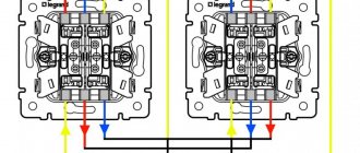
The pass-through switch should have three contacts - instead of two, as in a conventional one. A three-core wire must be laid between the switches, which can be hidden in the wall, but for this it must be grooved, or external wiring must be used. Switches are always connected so that the phase always goes to the switch, and not to the lamp. The phase always goes into the circuit break, and the zero is always connected to the light source.
Through the electrical junction box, wire 0 goes to the lamp, phase goes to the switch - to the input, two wires go to the output - the jumper closes the circuit alternately, with one or the other cable. These two wires go to another switch, and one cable comes out of it to the lamp. Current is transferred from one line to another.
You can make a device for automatic lighting control yourself. For example, there are several ways to assemble photo relay circuits with your own hands. A simple one - using a KT315B type transistor, and a more complex one - using a Q6004LT (quad).
Ultrasonic sensors and motion detectors are widely used for the same purposes. The latter of them can also be assembled independently at home.
To remake an ordinary switch at a walk-through, you need two switches from the same company and necessarily the same size: one-key and two-key. You need to buy a two-key switch whose terminals can be swapped so that the two circuits close/open independently of each other. Thus, in one position one circuit will be turned on, in another - another.
For remodeling, single-key switches for open wiring are most often used. Since it is difficult to find a pass-through switch for external wiring.
Place one key on the front panel (of the same size as the two-key one) instead of two, and the pass-through switch is ready!
Why do energy-saving lamps blink?
The LED switch is not compatible with energy-saving lamps. A device conflict manifests itself in a short-term flashing of the lamp when it is off or in the so-called smoldering mode, when the lamp does not turn off completely, but barely glows.
The service life of an LED or energy-saving lamp in the wrong mode is significantly reduced and ranges from one to two months
This happens because inside the fluorescent lamp there is an electronic converter (capacitor), which, gradually recharging from the current passing through the backlight lamp, flares up.
A similar phenomenon occurs with LED strip power supplies, which also have a capacitor and are powered by a small current coming from the backlit switch.
Manufacturers of energy-saving lamps indicate that the use of their products is not compatible with the use of LED switches and dimmers.
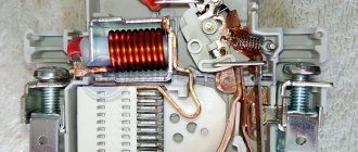
You can get around this limitation by controlling the operation of the lighting device using a relay. From the switch, the command first goes to the relay, which directly controls the lighting.
The relay is produced by many manufacturers of electrical goods: Schneider Electric , ABB , Siemens . You can place it under the chandelier cap, behind the cornice in which the LED strip is installed.
You can use another solution to the problem - disconnect the neon lamp or LED from the power supply. This can be done by disconnecting the backlight wires from the terminals. But then the LED switch will lose its advantages.
Let's consider solutions that still allow you to combine lighting and the use of energy-saving lamps.
Examples of calculations
Since our task is only to illuminate the switch and achieve maximum viability, we take the LED current 30% of the nominal - 6mA
Resistor current limiter
Usd=3.5V, Isd=20mA (0.02A) - We do the calculation at 6mA (0.006A);
R1= (330-3.5) /0.006=55000 Ohm (55 kOhm). In order to reduce heating, the resistor value can be doubled to 100 kOhm.
Resistor power P=Ur1I=3270.006=2W.
It is better to mirror a 1000V diode in parallel with the LED.
Capacitive current limiter
Instead of a resistor, you can use a high-voltage capacitor; R1 is necessary for the self-discharge of capacitor C1. The capacitive circuit does not heat up.
C1=Rc/(2π£)=50kOhm/(23.1450Hz)=150μF; C1=150uF*500V;
R1=0.5-1 MOhm;
The diode is the same as in the previous design.
If the switch is intended for an energy-saving lamp, it is better to replace the LED with a neon lamp, the donor of which will be the starter of the fluorescent lamp. Classical circuits, due to half-wave damping, can cause flickering of “energy-saving” devices. The connection principle remains the same, but due to the higher rated current, about 100 mA, the resistor or capacitance (on a neon light bulb) should be increased to 500-600 kOhm.
DIY illuminated switch
During the operation of electrical equipment, it sometimes turns out that in some of the rooms it would be nice to have a backlit switch. To do this, you don’t have to buy a device - you can improve your old one yourself.
What you will need for this:
- regular switch;
- LED with any characteristics;
- 470 kOhm resistor;
- diode 0.25 W;
- the wire;
- soldering iron;
- drill.
Using a soldering iron, they begin to assemble the circuit. The cathode of the diode (marked with a black stripe) is connected to the anode of the LED (the anode has a longer leg). The resistor is soldered to the positive terminal of the LED and to the wire that will serve as the connection to the switch. The second wire is connected to the cathode of the LED.
If you do not have a resistor of suitable power at hand or there is not enough space for placement, then it can be replaced with two resistors of lower power by connecting them in series (+)
Next, connect everything to the on-off mechanism. The phase conductor that leads to the lamp is connected to the terminal along with one of the wires leading to the LED. Another wire is connected to the input terminal along with the phase wire, which supplies current from the mains.
It is necessary to carefully insulate the exposed sections of the wire and prevent the conductors from touching the housing; this is especially important to do if it is metal.
Check the connection diagram of the backlit switch for functionality as follows: the key, closing the contact, causes the chandelier or lamp to light up; when it is off, the LED lamp lights up. If the circuit works correctly, you can install the device in the housing.
To make the lighting visible, place the LED lamp into a drilled hole at the top of the housing. This is not necessary if the body is light - the light will break through it.
The switch can be illuminated using a neon lamp. The circuit uses a HG1 gas-discharge lamp and any type of resistance with a nominal value of 0.5-1.0 MOhm with a power of more than 0.25 W (+)
Miniature motion sensor
There are similar types of motion sensors. That is, not those healthy boxes that hang on the walls or under the ceiling, but the same miniature switches assembled on a narrow circuit board.
They are also built into the profile or directly into the furniture. Their main difference is the range of action. Here we are no longer talking about a few centimeters, but about a distance of 2-3 meters.
Such sensors can be connected to organize lighting on the ceiling or floor in the corridor. It is very convenient to insert them into baseboards.
If you have such a motion sensor, you just need to enter the room and the light will turn on automatically. If there is no activity for about 30 seconds, the light turns off.
The coverage angle of the device is about 100 degrees. Based on this, calculate its placement.
The element that reacts to movement must also be removed from the housing. Drill a hole of the required diameter in the profile or lamp and place the cap outward.
Everything else, along with the wires, remains hidden inside.
Switch with on indicator
Switches with indicators differ from LED switches in a completely different principle of use - the lamp in them lights up when the lighting is turned on. The main purpose of a pilot light is to signal that lights are on in a basement, attic, storage room or outdoors.
Used to control energy consumption. The indicator can be set for each of the keys or only for one of them.
The connection and operation diagram of a switch with a backlight function is built according to the following principle. The test lamp is connected in parallel to the switch terminals. When the circuit is completed, current flows through the indicator and the light fixture - both light up. If the switch is off, no current flows to either the indicator or the lamp.
Indication of switched-on lighting can be done in combination: 1 indicator lamp per key or one lamp for each key (+)
Connection
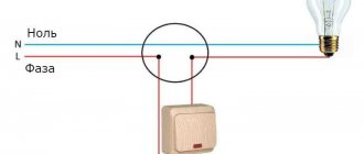
After studying the design of the switch, you can directly connect the switch. For those who are faced with a similar task for the first time, it is recommended to draw up in advance a diagram according to which the wires will be laid to the switch and lighting fixtures.
The standard connection diagram includes a live phase wire. It is designated by the letter L and is connected to the lamp through a switch. In addition to it, there is a neutral or neutral wire N, which is connected directly to the lamp socket. If there is a ground wire, it is also connected directly to the lamp.
Wires can be laid in a closed or open way, if the connection diagram provides for this. In the first case, you will need to install grooves in the walls, in the second - corrugated pipes or cable channels. For hidden wiring, a hole is drilled in the wall for the switch.
In order to ensure a reliable connection and high-quality contact with the terminals, the end of each conductor is stripped to approximately 1-1.5 cm. When using stranded wires, it is recommended to crimp their ends. Three wires are supplied to the two-key switch. The first is phase and is supplied to the input, and the second and third go to the output and are supplied directly to the lamp. The neutral and grounding conductors are connected to the contacts of the light sources. The location of the phase wire entry is indicated inside the switch by an arrow. The phase itself is determined by the tester.
After all the wires are in place and the double backlit switch is connected, it is necessary to isolate potentially dangerous areas. Then the entire structure, along with the wires, is installed in the installation box and secured with braces using screws. Upon completion of the main work, you need to install the decorative panel and both keys in place.
If there is a backlight, to connect a double switch, you must use additional wiring connected to the mini-indicators installed on the keys. One of them is connected to the input phase in the upper part, and the other is connected to one of the wires going to the lamps. When the light is turned off, the colored indicators on each key will continue to glow.
Possible problems
If you follow the rules and do everything according to the instructions, there will be no problems. The problem can only arise if you buy a “semi-finished product” . In it, the light bulb lies next to the switch in the package. But it’s hard to call it a problem. Rather, at the moment it is a small obstacle. In this case, you need to connect the two wires of the light bulb to different wires of the socket box.
If the switch is single-key. When connecting a two-key device, the indicator lamps are connected by one wire, and the others are connected to different phases. It doesn't matter which ones.
A switch with an LED differs from a regular switch only in the light bulb . No need to worry about spooled kilowatts. The backlight consumes a tiny fraction of electricity. Only works when the lights are off.
Connection rules
Regardless of the type, installing an illuminated switch is the same. The differences are only in a couple of nuances.
Installation of a single switch
The easiest way is to connect a single-key (single) backlit switch. First of all, you need to turn off the power and remove the old switch.
For this:
Use a flathead screwdriver to remove the key. Carefully remove the decorative trim. Unscrew the screws connecting the device to the socket box. Pull it out. Loosen the fastenings, disconnect the wires. After completing the manipulations, the inside of the dismantled switch remains on your hands
They are thrown away or used as spare parts
At the end of the manipulations, the inside of the dismantled switch remains on your hands. They are thrown away or used as spare parts.
To install a new light switch with indicator/backlight, you must repeat the steps listed above, only in reverse order:
- Insert the “internals” into the socket box, not forgetting to attach the wires to the switch contacts.
- Screw in the bolts.
- Install a decorative frame.
- Insert a key.
- Turn on the electricity to check the correct installation and connection. If the work is done correctly, the diode in the backlight will light up.
Installation and connection of switches with several keys
Connecting a double or triple backlit switch is done in much the same way. To install a design with two keys, you will need a screwdriver, side cutters, tips and an indicator with which to determine the phase.
The work is carried out like this:
As in the previous case, first of all it is necessary to turn off the power to the apartment/house. Next, the dismantling of the old device begins. Remove the keys and unscrew the screws. There will be three wires left in the socket box. One is incoming power, two more are power going to the lighting fixture. Now, using an indicator screwdriver, you need to find the phase wire, mark it or simply remember it
You need to act extremely carefully, because this stage requires the presence of voltage in the network. Disconnect the network. Strip the wires of insulation. Get a new device. It has three contact groups and a pair of wires coming from the backlight. Using a measuring device, determine the “Off” position.
Typically, the wiring coming from the LED has special contact plates for screws. The screw must be unscrewed, placed against the plate and screwed back. Repeat the action for the remaining contacts. Attach the phase wire to a plate located separately from the rest with a screw. Connect the wire going to the chandelier to the contact and secure it. Secure the last wire under the contact on which there are no plates. Check that the connection is correct. Insert the inner part of the switch into the installation box. Secure the screws. Reinstall the keys.
Upon completion of installation, connect the electricity and check the functionality of the device.
If it is necessary to control the light source from different places, a pass-through/changeover switch should be installed. Its main difference from classical models is the presence of a moving contact. If you press the on/off key, it will transfer from one contact to another, starting the operation of the second circuit.
Connecting a pass-through switch with backlight
The connection diagram for the pass-through switch is extremely simple. Two separate devices are installed on both sides of the circuit.
To do this, you will need to lay a three-core cable to one and to the other. When the first switch is turned on, the circuit will close and the lamp will light. When the second one is turned on, the light will turn off.
Other causes of flickering
The above methods for eliminating the flickering of lamps with LED lamps are related to the switch. But there are exceptions when the light flickers and the switch is compliant.
Causes:
- Low-quality energy-saving light bulb. It is more often observed in cheap Chinese-made products, when the lamp is defective from the factory. You'll have to spend money again and buy a good lamp.
- The service life of the diode lighting device has expired. The microcircuit element may have failed. As a result, the lamp glows, but blinks and crackles. There is no need to think that if the manufacturer provides an almost 10-year service life for the product, the lamp should work all the time. The service life of even a high-quality device is significantly reduced if voltage drops periodically appear in the network or the device operates at temperatures outside the standards determined by the designers.
In conclusion, it should be noted that if you postpone the search for a solution to the cause of the flickering light bulb, the energy-saving device will soon fail.
LED lamps are designed in such a way that each blink means the device is turned on. The service life of the lamps is tied to the number of switches on/off: the more often it flickers, the faster it will burn out. While repairing the lighting fixture, you can replace the LED with an incandescent lamp or temporarily install a regular switch.