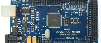
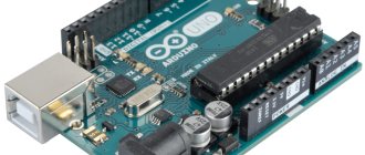
The Arduino Mega 2560 board is based on the ATmega2560 microcontroller. The board has 54 digital I/O pins, 15 of which can be used as PWM outputs, 16 analog inputs, 4 hardware serial UART ports, 16 MHz crystal, USB port, power connector, ISCP (In Circuit Serial Programming) connector , programming in the device using a serial protocol) and a reset button for the microcontroller. In order to start working with this board, you just need to connect it using the USB interface to the computer, or simply supply power from a DC source, which can also be a battery. The Arduino Mega 2560 is compatible with most expansion boards (shields) designed for the Arduino UNO, Duemilanove or Diecimila.
Arduino Mega 2560 replaced the Arduino Mega board.
Mega 2560 differs from all previous boards in that it does not use FTDI USB-to-serial hardware bridges. Instead, it has an ATmega16U2 microcontroller (ATmega8U2 in board versions 1 and 2) programmed to act as a USB-to-serial converter. In the second revision, the Mega2560 has a resistor that pulls the 8U2 HWB line to ground, which makes it easier to switch to DFU mode.
The following changes have been made to the Arduino Mega 2560 in revision 3:
- Pinout 1.0: SDA and SCL pins have been added, located next to the AREF pins, and two other new pins have been placed next to the RESET pin. IOREF allows shields to adapt to the voltage supplied from the board. In the future, shields will be compatible with boards based on AVR microcontrollers, operating at 5 V, and with Arduino Due, operating at 3.3 V.
- The RESET circuit has been strengthened.
- ATmega 8U2 was replaced with 16U2.
Schematic, datasheet, pinout
Download technical manual for microcontrollers ATmega 640/1280/1281/2560/2561:
Datasheet ATmega640/1280/1281/2560/2561 Atmel-2549-8-bit-AVR-Microcontroller-ATmega640-1280-1281-2560-2561_datasheet.pdf
8.4 MiB 2044 Downloads Details
| Category: | Documents |
| Date: | 20.04.2015 |
Download Eagle CAD files for Mega 2560 PCB:
Mega 2560 R3 in Eagle arduino-mega2560_R3-ref-design.zip
156.2 KiB 1322 Downloads Details
| Category: | Documents |
| Date: | 20.04.2015 |
Download the circuit diagram for Arduino Mega 2560:
Mega 2560 R3 circuit diagram arduino-mega2560_R3-sch.pdf
47.1 KiB 2551 Downloads Details
| Category: | Documents |
| Date: | 20.04.2015 |
Pinout diagram of the ATMega2560 microcontroller and their designation on the Arduino board:
Download pin designation as an archived SVG file:
Pinout m/k Mega2560 pin_mapping_mega2560.zip
17.3 KiB 1321 Downloads Details
| Category: | Documents |
| Date: | 20.04.2015 |
Pinout of the Arduino Mega 2560 board (click on the picture to enlarge).
Attention
Mega 2560 board
is equipped with a resettable fuse that protects
USB
ports from short circuits and overvoltage.
While most computers have their own protection against such mishaps, this fuse adds another layer of protection to it all. If
more than 500 milliamps
are applied the USB , the fuse will automatically interrupt the connection until the short circuit or overvoltage is corrected.
Characteristics of Arduino Mega 2560
| Microcontroller | ATmega2560 |
| Operating voltage | 5 V |
| Input Voltage (Recommended) | 7-12 V |
| Input voltage (limit) | 6-20 V |
| Digital inputs/outputs | 54 (of which 15 can work as PWM outputs) |
| Analog inputs | 16 |
| Max input/output current | 40 mA |
| Max current for 3.3V output | 50 mA |
| Flash memory | 256 KB of which 8 KB is used by the bootloader |
| RAM (SRAM) | 8 KB |
| Non-volatile memory (EEPROM) | 4 KB |
| Clock frequency | 16 MHz |
Nutrition
Arduino Mega can be powered from a USB port or an external source. The power source is selected automatically.
External power (not via USB) can be supplied from a power supply or battery. The power supply connects to a 2.1 mm connector on the board, which has a central positive pin. Battery power can be connected to the GND and VIN pins of the POWER connector.
The board can operate from an external voltage source in the range from 6 to 20 volts. If the power supply voltage is less than 7 V, the 5 V pin may have less than 5 V and the board may become unstable. If the external source voltage exceeds 12 V, the voltage regulator may overheat and damage the board. The recommended supply voltage range is 7-12 volts.
Power pins:
- VIN _ Input voltage of the Arduino board when using an external source (if there is no 5 volt voltage from the USB connection or other power source). You can supply power to this pin, or, if power is supplied to the 2.1 mm jack, then you can get the supply input voltage from this pin.
- 5V . The voltage at these pins is regulated by the voltage regulator built into the board. The board can be powered either via the 2.1mm power jack (7-12V), via the USB connection (5V), or via the VIN pin (7-12V) on the board. Supplying power through the 5V or 3.3V pins bypasses the regulator and can damage the board. This is not recommended.
- 3V3 . A voltage of 3.3 volts is generated using a regulator built into the board. The maximum current consumption should not exceed 50 mA.
- GND . Conclusions of the earth.
- IOREF . This pin provides the reference voltage with which the microcontroller operates. To properly configure external boards, you can read the voltage from this pin and select the appropriate power supply or enable voltage converters to operate with 5 V or 3.3 V.
Inputs and outputs
Each of the 54 digital pins on the Arduino Mega can operate in either input or output mode using the pinMode, digitalWrite and digitalRead functions. The outputs operate at 5 V. Each pin can send or receive a maximum of 40 mA and has an internal pull-up resistor of 20-50 kOhm (disabled by default). Plus, some pins have special functions:
- Serial: 0 (RX) and 1 (TX); Serial 1: 19 (RX) and 18 (TX); Serial 2: 17 (RX) and 16 (TX); Serial 3: 15 (RX) and 14 (TX). RX is used to send data over a serial port with TTL logic levels, and TX is used to receive data. Pins 0 and 1 are also connected to the corresponding pins of the ATmega16U2 USB-to-TTL converter chip
- External interrupts: 2 (interrupt 0), 3 (interrupt 1), 18 (interrupt 5), 19 (interrupt 4), 20 (interrupt 3) and 21 (interrupt 2). These pins can be set to low, rising or falling edge, or edge. For more details, see the description of the attachInterrupt function.
- PWM: 2 to 13 and 44 to 46. Provide 8-bit PWM signal output using the analogWrite function.
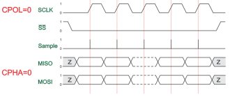
- SPI: 50 (MISO), 51 (MOSI), 52 (SCK), 53 (SS). These pins support SPI data transfer using the SPI library. SPI pins can also be routed to an ISCP block, which is physically compatible with Uno, Duemilanove and Diecimilia.
- LED: 13. This is a built-in LED on the board, which is connected to pin 13. When the pin is HIGH, the LED turns on; when it is low, the LED turns off.
- TWI (I2C): 20 (SDA) and 21 (SCL). Provides I2C communication using the Wire library. The location of these pins is different on Duemilanove or Diecimila boards.
Mega2560 has 16 analog inputs, each providing 10-bit resolution (1024 different values). By default, the voltage is measured between ground and 5 volts, although it is possible to change the upper range using the AREF pin and the analogReference function. Read more in the article Analog measurements with Arduino.
There are a couple more pins on the board:
- AREF. Reference voltage for analog inputs. Used with analogReference.
- RESET. A low signal at this input resets the microcontroller. Typically, an additional reset button is used on shields that block the reset button on the Arduino board itself.
Briefly about the chip
The ATmega2560 chip is an 8-bit AVR device with 256K ISP Flash memory, the contents of which can be changed by a standard programmer via a serial port or by a program launched by the AVR core code.
The chip is based on the AVR core using RISC architecture.
This allowed the ATmega2560 to achieve 1 million operations per second at a frequency of 1 MHz in one cycle.
Processor pinout diagram
The ATmega2560 chip is manufactured in a plastic QFN/MLF package with 64 pins.
Chip pinout:
| pin | meaning | pin | meaning | pin | meaning | pin | meaning |
| 1 | C0B PG5 | 17 | INT7 PB7 | 33 | PG0 WR | 49 | PA2 AD2 |
| 2 | INT0 PE0 | 18 | SC2 PG3 | 34 | PG1 RD | 50 | PA1 AD1 |
| 3 | INT1 PE1 | 19 | SC1 PG4 | 35 | PC0 A8 | 51 | PA0 AD0 |
| 4 | INT2 PE2 | 20 | RESET | 36 | PC1 A9 | 52 | VCC |
| 5 | INT3 PE3 | 21 | VCC | 37 | PC2 A10 | 53 | GND |
| 6 | INT4 PE4 | 22 | GND | 38 | PC3 A11 | 54 | PF0 ADC7 |
| 7 | INT5 PE5 | 23 | XTAL2 | 39 | PC4 A12 | 55 | PF0 ADC6 |
| 8 | INT6 PE6 | 24 | XTAL1 | 40 | PC5 A13 | 56 | PF0 ADC5 |
| 9 | INT7 PE7 | 25 | SLC PD0 | 41 | PC6 A14 | 57 | PF0 ADC4 |
| 10 | INT0 PB0 | 26 | SDA PD1 | 42 | PC7 A15 | 58 | PF0 ADC3 |
| 11 | INT1 PB1 | 27 | RD1 PD2 | 43 | PG2 ALE | 59 | PF0 ADC2 |
| 12 | INT2 PB2 | 28 | TX1 PD3 | 44 | PA7 AD7 | 60 | PF0 ADC1 |
| 13 | INT3 PB3 | 29 | CP1 PD4 | 45 | PA6 AD6 | 61 | PF0 ADC0 |
| 14 | INT4 PB4 | 30 | CK1 PD5 | 46 | PA5 AD5 | 62 | AREF |
| 15 | INT5 PB5 | 31 | T1 PD6 | 47 | PA4 AD4 | 63 | GND |
| 16 | INT6 PB6 | 32 | T0 PD7 | 48 | PA3 AD3 | 64 | AVCC |
The AREF contact serves to supply a reference voltage relative to which the ADC operates. Its stability determines the accuracy of the readings of all analog signal converters.
Connection
The Arduino Mega 2560 has several different capabilities for communicating with another computer, another Arduino board, or another microcontroller. The ATmega2560 has 4 hardware UART ports for serial communication with TTL levels (5 volts). ATmega16U2 (ATmega 8U2 on revision 1 and 2 boards) redirects one of the channels via USB and provides a virtual COM port for software on the computer (computers running Windows require an .inf file, but computers running Mac OS X and Linux recognize the board as COM port automatically). The Arduino IDE has a port monitor that allows you to send and receive simple text data to the Arduino board. The RX and TX LEDs flash to indicate data is being transferred via the ATmega8U2/ATmega16U2 chip and the USB connection to the computer (but not when data is being transferred via the serial port using pins 0 and 1).
The SoftwareSerial library allows you to work with a serial port connection for any Mega 2560 digital pins.
ATmega2560 also supports I2C and SPI communication. To simplify the use of exchange via the I2C protocol, the Wire library is used, and for communication via SPI, a library with the same name SPI is used.
Installing drivers
If you used the installer, Windows - from XP to 10 - will automatically install the drivers as soon as you connect your board. If you downloaded and extracted the Zip archive or for some reason the board is not recognized correctly, follow the procedure below.
- Click on the Start and open Control Panel.
- Go to the “ System and Security ” section. Then click "System". Then open Device manager.
- Look under Ports (COM & LPT ). You should see an open port named “ USB Serial Device ”. If the COM and LPT section is missing, look at the Other Devices, Unknown Device section.
- Right-click on the USB Serial Device and select the " Update Drivers... " option.
- Then select the “ Browse this computer for driver software ” option.
- Finally, locate the driver file named " arduino.inf " which is located in the " Drivers " folder of the Arduino program (not the "FTDI USB Drivers" subdirectory).
- Windows will then complete the driver installation.
Programming
Arduino Mega can be programmed using the Arduino IDE.
The ATmega2560 microcontroller on the Arduino Mega board comes with a firmware bootloader that allows you to load new code into the microcontroller without using an external hardware programmer. The bootloader uses the original STK500 protocol (C header files).
You can not use a bootloader and program the microcontroller through the pins of the ISCP block using Arduino ISP or similar.
The source code for the ATmega16U2 (or 8U2 in board versions 1 and 2) firmware is available for download in the Arduino repository. ATmega16U2/8U2 boots using the DFU bootloader, which is activated as follows:
- On version 1 boards: close the jumper on the back of the board (next to the map of Italy) and reboot 8U2.
- On version 2 or later boards: There is a resistor that pulls the 8U2/16U2 HWB line to ground, making it easier to enter DFU mode. You can use software from Atmel called Flip (for Windows) or DFU programmer (Mac OS X and Linux). You can also rewrite the firmware with an external programmer using the ISP connector (by rewriting the DFU bootloader). Details here.
Automatic (soft reset)
Instead of physically pressing the reset key before booting, the Arduino Mega 2560 is designed in such a way that it allows a soft reset from the connected computer. One of the lines that controls the data flow of the ATmega8U2, the DTR line, is connected to the reset line of the ATmega2560 through a 100 nF capacitor. Activating this line using a low voltage level allows the chip to be reset. The Arduino software takes advantage of this by allowing you to download code by simply clicking the download button in the Arduino environment. The low level signal is synchronized with the start of code recording, which reduces the bootloader timeout.
This has another application. When the Mega 2560 is connected to a computer running Mac OS X or Linux, a soft reboot (via USB) occurs every time. The bootloader program on the Mega 2560 takes about half a second to complete. During the programming process, the first few bytes of the code are delayed to avoid receiving incorrect data (all except the code of the new program). If you are doing a one-time debugging of a sketch written into the platform, or entering any other data at the first launch, you need to make sure that the program on the computer waits for a second before transferring the data.
On Mega2560 it is possible to disable the automatic reboot line by breaking the corresponding line. To restore the line, it is necessary to reconnect the contact at the break. The line is labeled "RESET-EN". It is also possible to disable automatic reboot by connecting a 110 Ohm 5 V resistor and this line. Details here.
Interesting projects
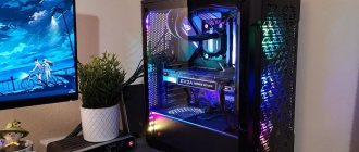
Smart home control systems are gaining popularity.
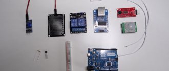
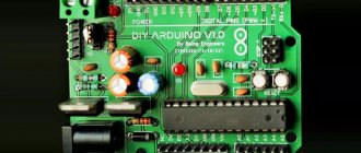
There are a lot of smart home implementations, some of them are controlled via a web interface, as described in the previous section. The photo below shows an example of the layout of such a system.
Here, to communicate with a smartphone, a special shield is used, its name is “1shield”. With the official app you can connect to your shield via WiFi or Bluetooth. In order to make it work with Arduino, you need to download 1shield library - a special library.
Another idea for such a powerful board is an electronic bartender on Arduino. If you can’t live without your favorite cocktails, but don’t want to learn how to make them, an Arduino robotic bartender will help you.
The project was based on Arduino Mega; to implement the mechanism for moving the glass and pouring drinks, a stepper motor (for longitudinal movement of the container) and a servo drive were used to open the robot valves.
Below is an example diagram of the device.
Physical characteristics and compatibility with expansion cards
The length and width of the Mega2560 PCB are 10.2 and 5.3 cm, respectively. The USB connector and power connector exceed these dimensions. Three holes in the board allow it to be mounted on a surface. The distance between digital pins 7 and 8 is 0.4 cm, although between the other pins it is 0.25 cm.
The Arduino Mega2560 is compatible with all expansion boards designed for the Uno, Duemilanove or Diecimila platforms. The layout of pins 0 – 13 (and adjacent AREF and GND), analog inputs 0 – 5, power connector, ICSP block, UART serial port (pins 0 and 1) and external interrupt 0 and 1 (pins 2 and 3) on Mega corresponds to location on the above platforms. SPI communication can be done via the ICSP block on both the Duemilanove/Diecimila and Mega2560 platforms. However, the layout of the I2C communication pins (20 and 21) on the Mega platform does not match the layout of the same pins (analog inputs 4 and 5) on the Duemilanove/Diecimila.
Content
- 1 Arduino Mega 2560[1] 1.1 Where to start
- 1.2 For inspiration
- 1.3 Technical specifications
- 1.4 Documentation
- 1.5 Programming
- 1.6 Attention
- 1.7 Power
- 1.8 Memory
- 1.9 Input and output contacts
- 1.10 Communication
- 1.11 Physical characteristics and shield compatibility
- 1.12 Automatic (software) reset
- 1.13 Versions
Arduino Mega 2560
is a microcontroller board based on the ATmega2560 chip.
It has 54 digital I/O pins
(of which
15
can be used for
PWM
),
16 analog input pins
,
4 hardware serial ports (UART)
16 MHz
crystal oscillator ,
USB
connection, power connector,
ICSP
comb and button reset.
It contains everything necessary for the operation of the microcontroller - to get started, the user just needs to connect it to the computer via a USB
cable or power it from an adapter that converts alternating current to direct current, or from a battery.
Mega 2560
board is compatible with most
shields
designed for Uno and older boards (Duemilanove or Diecimila).
Arduino Mega 2560 board
replaced
Arduino Mega
.
Warranty information can be found here.