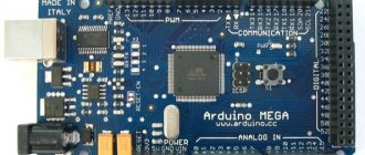
What is Arduino?
Arduino is a company that develops devices and programs for robotics and more. In fact, the company began in 2003, when Hernando Barragan created the first version of the Arduino Wiring platform as part of his educational work.
Wiring is a C/C++ programming language library. This "extension" is designed to work with Arduino boards. The Arduino IDE is used to transfer code to our board . This is where the program is written.
Arduino IDE development environment
Other number systems
Data in the microcontroller's memory is stored in binary representation, but in addition to it, there are other number systems in which we can work. Try to immediately remember and understand that there is no need , Arduino absolutely does not care in what format you feed the variable value, they will automatically be interpreted in binary form. Different number systems were introduced primarily for the convenience of the programmer . Now, in essence: Arduino supports (and in general, nothing else is needed) four classical number systems: binary, octal, decimal and hexadecimal. Yes, and we got to her. A quick reminder: the hexadecimal system has 16 values per digit, the first 10 are the same as the decimal system, the rest are the first letters of the Latin alphabet: 0, 1, 2, 3, 4, 5, 6, 7, 8, 9, a, b , c, d, e, f . With the decimal system everything is simple, we write the numbers the way they look. 10 is ten, 25 is twenty-five, and so on. Binary has a prefix of 0b (zero be) or B , that is, the binary number 101 will be written as 0b 101 OR B 101. Octal has a prefix of 0 (zero), for example 012 . Hexadecimal is prefixed with 0x (zero x), FF19 will be written as 0x FF19.
| Basis | Prefix | Example | Peculiarities |
| 2 (binary) | B or 0b (zero be) | B1101001 | numbers 0 and 1 |
| 8 (octal) | 0 (zero) | 0175 | numbers 0 – 7 |
| 10 (decimal) | No | 100500 | numbers 0 – 9 |
| 16 (hexadecimal) | 0x (zero x) | 0xFF21A _ | numbers 0-9, letters AF |
The main feature of the hexadecimal system is that it allows long decimal numbers to be written shorter, for example one byte (255) will be written as 0xFF, two bytes (65,535) as 0xFFFF, and the dreaded three bytes (16,777,215) as 0xFFFFFF. You have no idea (or already have an idea) how convenient and clear this allows you to work with colors and shades. The binary system is usually used to visually represent data and low-level configurations of various hardware. For example, the config is encoded in one byte, each bit in it is responsible for a separate setting (on/off), and by passing one byte of the form 0b10110100 you can configure a bunch of things at once, we will return to this in the lesson on working with registers from the section of advanced lessons. In the documentation about this they write in the style of “the first bit is responsible for this, the second for that” and so on.
Installing Arduino IDE
To use the Arduino IDE, you can install the program on your computer or use the online version of the program (registration required). Let's look at how to install the program on Windows 8/10.
- Go to the official Arduino website. In the Download section, select the required operating system.
- We get to a page with the opportunity to donate money for the further development of Arduino. Click on the “Just download” button to install the program without donations.
3. We are sent to the Microsoft Store website, where we click “Get.”
The program is installed and ready to use.
Custom Types (Pro)
The language has a typedef tool that allows you to create your own data type based on another standard one. For what? On the one hand, for the convenience of the programmer, on the other, to confuse him =) I have never used it, but to parse other people’s codes from the Internet, you need to know this! So, typedef works like this: typedef type name; – create a new data type name based on the type type. Example:
typedef byte color;
Creates a data type called color, which will be absolutely identical to the byte type (that is, accept 0-255). Now you can create variables with this type:
color R, G, B;
We created three variables of type color, which is the same byte, only in profile. This is all! There is another important point regarding struct structures and enum enums - in code from the Internet you will often see the use of typedef before struct and enum. In pure C this makes a lot of sense, but in C++ it is the opposite of a problem. typedef in Arduino firmware is used by programmers who came from C and use typedef out of habit; on pluses there is no need to do this .
Why you shouldn't use typedef for struct and enum
In the C language (without ++), when creating a structure/enumeration using a shortcut, you need to write the word struct/enum before the shortcut, otherwise there will be an error. Or the structure itself must be declared as a typedef // IN SI, NOT ++ // do this struct myStruct { byte x; byte y; }; struct myStruct kek; // create a structure kek // or so typedef struct myStruct { byte x; byte y; }; myStruct kek; // create a kek structure In C++ (and Arduino) you don’t need to do this! On the contrary, typedef in this application can lead to errors. For example:
// using typedef you cannot // declare a structure immediately. // This will lead to an error when // trying to access a member of the structure typedef struct { byte x; byte y; } kek; // this will also lead to an error typedef struct myStruct { byte x; byte y; } kek; // The only option is to // work on the shortcut typedef struct myStruct { byte x; byte y; }; myStruct kek; // seriously, do you need such problems?
Arduino IDE Hotkeys
To simplify work, the Arduino IDE uses “hot keys” or hotkeys , from the English hotkeys, which in translation means “hot keys”. These are combinations of keys on the keyboard that perform various actions in the operating system and programs. All commands are available through the “File” menu, but working through hotkeys is much faster.
Let's look at the hotkeys and their purpose.
Edit
| Ctrl+Z | canceling one operation |
| Ctrl+Y | return one canceled operation |
| Ctrl+F | search by code |
| Atrl+A | highlighting all code |
| Ctrl+P | print tab contents |
| Ctrl+X | cut the highlighted code |
| Ctrl+C | copy highlighted code |
| Ctrl+V | paste highlighted code |
Compilation and loading
| Ctrl+R | sketch compilation |
| Ctrl+U | upload sketch |
| Ctrl+Shift+U | upload the sketch using the programmer |
Saving and working with tabs
| Ctrl+S | save current sketch |
| Ctrl+Shift+S | save the current sketch with a choice of the name of the saved file |
| Ctrl+W | close current tab |
| Ctrl+Shift+N | new inset |
| Ctrl+Alt+Right Arrow | switch to the tab to the right of the active one |
| Ctrl+Alt+Left Arrow | switch to the tab to the left of the active one |
Other
| Ctrl+N | open a new editor window |
| Ctrl+O | open an existing sketch file |
| Ctrl+Slash ( / or Russian dot) | commenting out a line |
| Ctrl+K | open folder with sketches |
| Ctrl+T | auto-formatting code |
| Ctrl+Shift+M | port monitor |
| Ctrl+, (Russian letter B) | Arduino IDE settings page. |
Syntax
- Function bodies are enclosed in curly braces { }
- Each command ends with a semicolon;
- The method is applied to an object through a point. Example: Serial.begin();
- A function or method call always ends with parentheses, even if the function takes no parameters. Example: loop()
- The decimal separator is a dot . Example: 0.25 The comma has another use here
- Commas list the arguments of functions and methods, as well as array members. Example: digitalWrite(3, HIGH); array – int myArray[] = {3, 4, 5,6}; Also, a comma is an independent operator, but we’ll talk about this separately in another lesson.
- A single character is enclosed in single quotes 'a'
- String and character array are enclosed in double quotes "string"
- Variable names can contain uppercase and lowercase letters numbers , and underscores . Example: myVal_35.
- Variable names cannot begin with a number . Only with a letter or underscore
- Case matters, i.e. a capital letter is different from a small letter. Example: the variables val and Val are not the same thing.
Syntax can also include comments, because They are highlighted differently in different languages. A comment is plain text that is ignored during compilation. Comments are needed to explain the code, both to yourself and to other possible readers. In C++ we have two types of comments:
- One-line comment // one-line comment // the compiler ignores me =(
- Multiline comment /* Multiline comment */
Program template. setup() and loop() functions
Comments
It is customary to include some comments at the beginning of the program. Here the author of the code can write about himself, about the program and its purpose. To indicate a comment at the beginning of a line, write 2 characters “//”, for example:
// The file “matrixb.h” contains the definition of the Matrix_B class, the implementation // of its methods in the program “program2.vcproj” // The Matrix_B class is the base class for the Matrix_D class // Program creator: Ivan Ivanovich Ivanov, 7a // Version 1.0 from 14.02 .14
Program template
The program itself resembles a home. Our “house” consists of 2 parts:
- The setup() function acts as the “foundation of the house.”
- The loop() function resembles the living part of a house: the program itself “lives” here.
Let's launch the Arduino IDE and write a program template:
void setup() { } void loop() { }
After setup and loop, the brackets () are written without a space. There is no space inside the brackets. The functions themselves are written in small letters. Curly braces are placed one below the other on the following lines after the function name.
If you wrote everything correctly, your function will become a different color.
Let's take a closer look at the purpose of each function.
setup() function
The setup() function is preparation. This is the first function performed by the program. It is performed only once, immediately after turning on the board or restarting it with the reset button. setup() is used to introduce new functions, configure board PINs, and create variables. The function must be included in the program even if there is no content in it.
loop() function
After the setup() function, control passes to the loop() function. Translated from English, “loop” is a loop. The function does exactly what its name means - it is continually re-executed. It allows the program to change something, return data and control the Arduino board.
From Arduino and wiring to AVR Studio and pure SI
Hello.
This article will appeal to those who believe that they have “grown up” from Arduino and are ready to step into the world of “serious” microcontroller programming. In addition to the fact that you will “pump up your programmer’s skills,” you will have the opportunity to choose any microcontroller for your projects, and of course you will appreciate the speed of the programs and the size of the memory they occupy.
Everything will be described (for), from start to finish - installation and preparation of the necessary software, assembly of the simplest Gromov programmer (don’t be scared, there are only three diodes and seven resistors), MK firmware and writing code in AVR Studio. The entire process will be accompanied by illustrations and examples.
Let me make a reservation right away: the computer must be equipped with a COM port (the USB to COM adapter does not work well). If your computer does not have such a connector on the back, then it is probably on the motherboard (in the form of pins), then everything can be solved with this “ejection”
Alas, for owners of laptops without COM, the article is of only academic interest.
So, let's begin…
What will you need?
"Soft"
UniProf is a universal program for flashing various ATmega microcontrollers, simple and convenient, and most importantly, works perfectly with our programmer. The author is Russian developer Mikhail Nikolaev.
Of course, you can flash the MK from AVR Studio, but for this you need a special programmer. Therefore, we will write the code in the studio, and flash the resulting hex files with UniProf using our homemade programmer. In addition, the method of flashing firmware from the command line will be described.
Linux users will have to use either a virtual machine or Wine. It didn’t work out for me with Wine, I can’t see the port at all, and I haven’t tried it with a virtual machine.
Download:
UniProf Simply unpack it to a convenient place.
AVR Studio is a programming environment developed by specialists from Atmel Corporation, which produces various microcontrollers (ATmega, XMEGA, MCS-51, ARM, AVR, AVR32), including those used in Arduino (ATmega168, ATmega328, ATmega32u4, MEGA2560) .
At the moment, the seventh version of this environment is available on the manufacturer’s website, but we will use the older and time-tested version 4.19 . It is stable, works on any, even outdated, hardware, includes everything you need and is still popular.
In addition, you will need the AVR toolchain compiler.
It works flawlessly in Wine (Debian 8.5, wine1.6).
Download:
AVR Studio 4.19
AVR toolchain First install the studio, and then the toolchain. Exactly in that order.
At the same time, download a text editor with a “human face” - Notepad++ , because the standard Notepad is the handicraft of a drunken devil.
Download:
Notepad++
All software is free.
"Iron"
We will conduct experiments on an Arduino pro mini with an ATmega328 chip. The quartz frequency (8/16 MHz), as well as the voltage (3.3/5v), do not matter. (see below)
In the future you will program various Atmel microcontrollers, but for the first time this board is just right. It is good because it is practically a bare controller with minimal wiring and soldered pins. Just what you need.
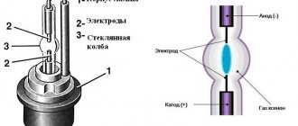
About markings on microcontrollers
After the name there are numbers, which most often indicate the amount of memory.
The letter after the numbers indicates the supply voltage parameters.
No letter - the controller supply voltage is in the range of 4.5-5.5 volts. L - versions of controllers operating at low supply voltage (2.7 - 5.5 volts). V - versions of controllers operating on low supply voltage (1.8-5.5 volts). U - versions of controllers operating on ultra-low supply voltage (0.7-5.5 volts). P - low-power versions (up to 100 nA in Power-down mode). A - current consumption is reduced, the entire clock frequency range of all versions is covered, supply voltage is 1.8-5.5 volts (in some models, new features and new registers have been added. At the same time, full compatibility with previous versions is maintained).
A " and "non- A microcontrollers usually have the same signature, which causes some difficulties since the Fuse-bits are different.
Examples:
ATmega8 - program memory capacity 8 kilobytes, supply voltage - 4.5-5.5 volts. ATmega8L - program memory capacity 8 kilobytes, supply voltage - 2.7-5.5 volts. ATtiny43U - memory capacity 4 kilobytes, modification - 3, supply voltage - 0.7-5.5 volts. ATtiny44A - memory capacity 4 kilobytes, modification - 4, reduced current consumption, supply voltage 1.8-5.5 volts.
It happens that a controller without a letter may have a reduced supply voltage (1.7 or 1.8 volts). This needs to be clarified in the datasheet.
Example:
ATtiny841 - memory capacity 8 kilobytes, modification - 41, supply voltage - 1.7-5.5 volts.
After the hyphen, the microcontroller version is indicated, consisting of numbers indicating the maximum frequency of the controller (at the appropriate supply voltage), and letters indicating the housing version, operating temperature range, and manufacturing features.
One or two letters following the frequency indicate the housing type:
P - DIP A - TQFP M - MLF TS - SOT-23 J - PLCC A - UDFN/USON C - CBGA CK - LGA S - EIAJ SOIC SS - narrow body JEDEC SOIC T - TSOP X - TSSOP
The next letter (after the housing type) indicates the temperature range and manufacturing features:
C - commercial temperature range (0-70°C). A - temperature range −20-85°C, using lead-free solder. I - industrial temperature range (-40-85°C). U - industrial temperature range (-40-85°C), using lead-free solder. H - industrial temperature range (-40-85°C), using NiPdAu. N - extended temperature range (-40-105°C), using lead-free solder. F - extended temperature range (-40-125°C). Z - automotive temperature range (-40-125°C). D - extended automotive temperature range (-40-150°C).
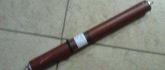
Programmer "Gromov"
Resistor power from 0.125 W. Diodes - any pulse ones, with a recovery time of no more than 50 ns (for example, 1N4148, KD522, KD510) I have 1N4001.
And the last thing is the response part of the COM port (DB9).
Do not use wires that are too long. There are 30 centimeters between the computer and the programmer, and 10-15 centimeters between the programmer and the MK. Power for the MK can be taken from the USB port.
My programmer looks like this:
Connection diagram
We connect the Arduino to the programmer...
... connect the programmer to the COM port and supply power.
If you have a 3.3v (8Mhz) arduino, then you can safely supply 5 volts to it. Here’s the thing, the controller can work with 16 MHz quartz only from 4.5 to 5.5 volts, if you apply less, the quartz will not “swing”, and if you set the quartz to 8 MHz, it will work in the range from 2.7 - 5v. This is how Arduinos are made with reduced power consumption, and 5 volts can be supplied to almost any ATmeg.
MOSI, MISO, etc., this is the SPI bus.
UniProf
Writing a program is half the battle; you still need to somehow cram it into the controller.
So let's pay more attention to this. It would be nice if your Arduino was loaded with standard Blink (it comes with it from the factory).
From here onwards, do not press any buttons without permission!
Let's launch UniProf... Perhaps the following window will pop up:
This is connected to the LPT port, so just click OK .
The program window will then open:
If the port is not selected correctly, a window will appear asking...
Click OK and select the desired port.
If the MK is not detected automatically, then a window with manual selection will appear:
Unfortunately, atmega328 , so select mega32 (they have the same amount of flash memory) and click OK .
After this, instead of the word unknown, the connected controller will appear...
32K is the amount of Flash memory, and 1024 is the amount of EEPROM.
Now, if everything is as in the picture, then open the help and carefully read what is written there. The author was very concise, so it won’t take much time. Don't press any buttons yet.
Have you met? Great, now we can move on. Uncheck the box next to EEPROM and you will see the changed interface:
After unchecking the EEPROM checkbox, reading and writing this memory area is not performed.
the General and BIN checkboxes , and also check the Brake checkbox! , this will increase the read/write time, but will increase stability.
Well, it's time to try to read our MK. Check back the EEPROM checkbox and press the Read button.
The process is not fast so you will have to wait. Blue squares will crawl below and numbers will be counted in the lower right corner. The first pass will read the PROGRAM area, and the second will read the EEPROM.
I have a new Arduino with a standard Blink built into it (when the programmer is connected, the diode will stop blinking). If you have the same thing, then the following picture will appear:
On the right we see that there is nothing in EEPROM, and on the left, in PROGRAM, there is a recorded program (as I already said, this is Blink). Now use the down arrow to scroll the slider until the data runs out...
...now scroll to the end. You will see more data - this is the Arduino bootloader.
Now I propose to take a break from my article and read about the structure of the MK here, this will greatly increase your understanding of the material. Everything is written very well and clearly. Well, once you’ve read it, come back and let’s continue...
Uncheck EEPROM . We don’t really need it, but it will be clear that the “Brake” checkbox is checked!
Now let's save everything that is firmware in the controller, so that after experiments we can return it to its original state.
Click the button and save the firmware by calling it something like origProMini328.hex . That's it, now you have a backup.
Let's move on. Press the button, thereby deleting everything from the controller...
... and then click the already familiar Read button. After this, you will see that all the cells in PROGRAM are empty. Not only the program was removed, but also the Arduino bootloader. That is, now you will not be able to upload sketches using the traditional method. Then, if you want, with a slight wave of your hand, restore everything from the backup.
Now we will flash the controller with the same “Blink”, only written in AVR Studio.
This is what the code looks like:
#define F_CPU 16000000UL #include #include #define PIN_PB5 5 // PB5 (Arduino - D13) #define PIN_PB5_PORT PORTB #define PIN_PB5_DDR DDRB int main(void) { PIN_PB5_DDR = 1 << PIN_PB5; // set PIN_PB5 (PB5 (arduino - D13)) as OUTPUT while(1) { PIN_PB5_PORT = 1 << PIN_PB5; _delay_ms(300); PIN_PB5_PORT = 0 << PIN_PB5; _delay_ms(300); } return 0; } If you use an Arduino with 8 MHz quartz, then there is nothing wrong with this, the diode will just blink half as often.
Here's how much space it takes up:
Download the file 328test.hex somewhere and open it with the button, then flash it with the button
Important! Before each firmware update, clean the controller with the button, and if you don’t remember whether you cleaned it or not, then check with the button
If you check the Write 0xFF checkbox, then all unused cells will be filled with the number 0xFFFF.
the Reset contact (the program presses it to ground, preventing it from starting) and the Arduino will come to life, blinking at intervals of 300ms. You can not disconnect the contact, but simply press the debug button. We will not discuss this button, since you will be doing debugging in AVR Studio.
After closing the debugging window, you need to reselect the controller if this does not happen automatically.
Please note that a sketch written in the Arduino IDE takes ~940 bytes, while in AVR Studio it takes 178 bytes. As for the speed of “twitching your legs” (if you remove the delay here and there), the difference will be about 20 times. This is due to the peculiarities of the Arduino IDE and the language used in it. However, you will soon become familiar with everything yourself.
There are two more buttons left - and , they are responsible for setting the fuses of the microcontroller.
Fuses are three or four (depending on the MK) bytes located in a certain memory area, the fuse bits of which are responsible for the controller configuration (clock frequency, use of internal or external quartz, enabling/disabling watch dog, etc.). etc.), they are not affected when flashing or erasing the controller and are installed separately.
The topic of fuses is serious and requires thoughtful study. Now we will not consider them for several reasons: firstly, the necessary fuse bits are already flashed in the Arduino, secondly, it will not be possible to change them correctly in the uniprof (ATmega328 is not on the list) and thirdly, it is better to postpone this for the future, when you get used to it and feel more confident.
To satisfy curiosity, click the button and in the window that opens, click the Read , but under no circumstances click Write ...
This is what fuse bits actually look like. I repeat, do not click Write , this will lead to unpredictable consequences since we have selected the mega32 , not atmega328 .
When it comes to them, then use an online calculator and find out which bit is responsible for what. For information on how to flash, see below.
Now close the fuse window and uniprof , and let's move on...
Added later. Here is a version of uniprof that has atmega328 . Author of the revision.
AVRDude
Uniprof, like many other similar programs, is only a graphical add-on to the AVRDude (AVR Downloader-Uploader) program, which then performs all the above actions on the microcontroller. Since AVRDude does not have its own graphical interface, you need to work with it from the command line. This may seem inconvenient to some, but it’s just the opposite; working from the console is simply great. Convenient, simple and not tied to any OS, because avrdude probably exists for everything. Now you will see this.
For users
Avrdude is included in the AVR toolchain, so install it (after installing AVR Studio) as written at the beginning of the article.
Open “Command Prompt” (hereinafter I will call it terminal) as an administrator, and with the command...
cd\... go to the root of
drive C.
By entering the command:
avrdude -h
You should see help information.
If everything is so, then avrdude is ready to go and you can continue.
Now we need to add our programmer to the avrdude (C:\Program Files (x86)\Atmel\AVR Tools\AVR Toolchain\bin\ avrdude.conf ). Open it in Notepad++ and after “PROGRAMMER DEFINITIONS” add the following lines:
programmer id = "gromov"; desc = "serial port banging, reset=dtr sck=rts mosi=txd miso=cts"; type = serbb; reset = 4; scck = 7; mosi = 3; miso = 8; ; The programmer uses Bit-banging technology.
Make sure that when copying, the quotes remain just quotes, otherwise they may change (due to the difference in encodings) and avrdude will swear.
Save and close the file; it is no longer needed.
Return to the terminal and give the command to check communication between the MK and the programmer:
avrdude -n -c gromov -P com1 -p m328p You may have a different com port.
If there is a connection, then the answer will be like this:
Next I will describe setting up avrdude for Linux, and after that I will write commands for both OS (since they are the same)…
Install avrdude
sudo apt install avrdude
By entering the command:
avrdude -h
You should see help information.
If so, then
avrdude is ready to go.
Configure the port:
sudo stty 9600 ignbrk -brkint -icrnl -imaxbel -opost -isig -icanon -iexten -echo noflsh This must be done after each computer reboot, or add it to rc.local.
Where /dev/ttyS0 is com1 , /dev/ttyS1 is com2 , etc. In the future, in commands I will write /dev/ttyS0 , you may have /dev/ttyS1 , etc.
Add the programmer to the /etc/avrdude.conf
sudo nano /etc/avrdude.conf
After “PROGRAMMER DEFINITIONS” add the following lines:
programmer id = "gromov"; desc = "serial port banging, reset=dtr sck=rts mosi=txd miso=cts"; type = "serbb"; reset = 4; scck = 7; mosi = 3; miso = 8; ; The programmer uses Bit-banging technology.
Make sure that when copying, the quotes remain just quotes, otherwise they may change (due to the difference in encodings) and avrdude will swear.
Save and close the file.
Give the command to check the connection between the MK and the programmer:
sudo avrdude -n -c gromov -P /dev/ttyS0 -p m328p
If there is a connection, then the answer will be like this:
This is where the differences between operating systems end and the commands are duplicated.
Add the argument -v or -v -v (can be added to any command) to the command to display complete information:
avrdude -n -v -c gromov -P com1 -p m328p ###WIN### sudo avrdude -n -v -c gromov -P /dev/ttyS0 -p m328p ###Linux###
Avrdude's conclusion is that both in Windows and in Linux are the same, so from now on I will take screenshots only in Win.
There is more information here, for example, you can see what fuses are installed. Here they are output in hexadecimal (HEX) numbers. For example, hfuse 0xDA, in the binary system it looks like this - 11011010. That is, these are the same bits that are checked off in graphical interfaces.
When you deal with fuses, remember that in ATmega microcontrollers the fuses are inverted. That is, 0 is enabled , and 1 is disabled . This causes confusion in online calculators (see below).
Let's read the firmware from the flash (the same as PROGRAM in uniprof) with the command:
avrdude -c gromov -P com1 -p m328p -U flash:r:readfl.txt:h ###WIN### sudo avrdude -c gromov -P /dev/ttyS0 -p m328p -U flash:r:readfl. txt:h ###Linux###
In uniprof the code was shown in the program, but here it will be written to a file.
The firmware has been read and written to the readfl.txt . The letter h (hex) at the end indicates that the data should be written in hexadecimal format. If you write the letter b (binary), it will be written in the binary system, and if r (raw), then the data will be in “raw” form (quacks).
From here on, it is assumed that win users are located in the root of the C (C:\), and linux users work from their home folder, so the files will be saved there (unless a different path is specified). The firmware that will be uploaded to the MK should be located there.
For win, the file will be located here C:\readfl.txt, and for linux, in /home/user/readfl.txt. You can open this file and take a look.
Reading EEPROM:
avrdude -c gromov -P com1 -p m328p -U eeprom:r:reader.txt:h ###WIN### sudo avrdude -c gromov -P /dev/ttyS0 -p m328p -U eeprom:r:reader. txt:h ###Linux###
Reading flash and eeprom together:
avrdude -c gromov -P com1 -p m328p -U flash:r:readfl.txt:h -U eeprom:r:reader.txt:h ###WIN### sudo avrdude -c gromov -P /dev/ttyS0 -p m328p -U flash:r:readfl.txt:h -U eeprom:r:reader.txt:h ###Linux###
Erasing the controller:
avrdude -e -c gromov -P com1 -p m328p ###WIN### sudo avrdude -e -c gromov -P /dev/ttyS0 -p m328p ###Linux###
Disconnect the “reset” pin - the diode will not blink, the program will be erased.
Let's flash the MK with the previously downloaded file 328test.hex . It is located in the root of drive C (c:\328test.hex) in Windows or in the home folder (/home/user/328test.hex) in Linux.
avrdude -c gromov -P com1 -p m328p -U flash:w:328test.hex ###WIN### sudo avrdude -c gromov -P /dev/ttyS0 -p m328p -U flash:w:328test.hex # ##Linux###
Now if you turn off the “reset”, the controller will come to life.
Note. When flashing the MK firmware via avrdude , it is not necessary to erase the controller; the program does it itself. However, if you specify the -D , then the MK will not be cleaned automatically.
EEPROM firmware:
avrdude -c gromov -P com1 -p m328p -U eeprom:w:eeprom.hex ###WIN### sudo avrdude -c gromov -P /dev/ttyS0 -p m328p -U eeprom:w:eeprom.hex # ##Linux###
Reading all fuses:
avrdude -c gromov -P com1 -p m328p -U hfuse:r:hfuse.txt:h -U lfuse:r:lfuse.txt:h -U lock:r:lock.txt:h -U efuse:r:efuse .txt:h ###WIN### sudo avrdude -c gromov -P /dev/ttyS0 -p m328p -U hfuse:r:hfuse.txt:h -U lfuse:r:lfuse.txt:h -U lock :r:lock.txt:h -U efuse:r:efuse.txt:h ###Linux###
Some controllers may not have any fuse.
Reading only Low fuse:
avrdude -c gromov -P com1 -p m328p -U lfuse:r:lfuse.txt:h ###WIN### sudo avrdude -c gromov -P com1 -p m328p -U lfuse:r:lfuse.txt:h ###Linux###
Low fuse is responsible for selecting the clock signal source (internal, external), its frequency and the pause before the controller starts after power is applied to it. Now you have a value written there - 0xff , which corresponds to external quartz from 8 MHz and above.
Now we will flash another lfuse, which will transfer your ATmeg to work from an internal 8 MHz generator.
avrdude -c gromov -P com1 -p m328p -U lfuse:w:0xe2:m ###WIN### sudo avrdude -c gromov -P /dev/ttyS0 -p m328p -U lfuse:w:0xe2:m # ##Linux###
If you have a 16 MHz Arduino, the diode will blink twice as slow. In the future, when coding in AVR Studio, you can specify a frequency of 8 MHz and unsolder the quartz, thereby getting two more free digital pins at your disposal.
But that’s later, and now let’s return everything as it was by flashing the previous fuse:
avrdude -c gromov -P com1 -p m328p -U lfuse:w:0xff:m ###WIN### sudo avrdude -c gromov -P /dev/ttyS0 -p m328p -U lfuse:w:0xff:m # ##Linux###
The diode will flash correctly.
Fuses can be flashed individually or together:
avrdude -c gromov -P com1 -p m328p -U hfuse:w:0xda:m -U lfuse:w:0xff:m -U efuse:w:0x05:m ###WIN### sudo avrdude -c gromov - P /dev/ttyS0 -p m328p -U hfuse:w:0xda:m -U lfuse:w:0xff:m -U efuse:w:0x05:m ###Linux### These commands do not need to be given. I present them for clarity.
In the future, when you need to use other controllers, you will check the boxes in the online calculator, get the values (from the link in the upper left corner) in hex format and flash them.
Here is a very good article about FUSE. And further…
avrdude parameters and you can move on to the final part.
-c gromov - type of programmer, or rather the name under which it is written in the config (avrdude.conf). -P com1 - well, everything is clear here. -p m328p - designation of MK type. -U - after this option, the memory area (flash, eeprom, xfuse) on which any actions will be performed is indicated (r - read, w - write). Colons serve as separators.
Here is a detailed help from avrdude, with the names of microcontrollers and their aliases, programmers and other options.
MK aliases uc3a0512 - AT32UC3A0512 c128 - AT90CAN128 c32 - AT90CAN32 c64 - AT90CAN64 pwm2 - AT90PWM2 pwm2b - AT90PWM2B pwm3 - AT90PWM3 pwm316 - AT90PWM316 pwm3b - AT9 0PWM3B 1200 — AT90S1200 (****) 2313 — AT90S2313 2333 — AT90S2333 2343 — AT90S2343 (*) 4414 - AT90S4414 4433 - AT90S4433 4434 - AT90S4434 8515 - AT90S8515 8535 - AT90S8535 usb1286 - AT90USB1286 usb1287 usb162 - AT90USB162 usb646 - AT9 0USB646 usb647 - AT90USB647 usb82 - AT90USB82 m103 - ATmega103 m128 ATmega128 m1280 - ATmega1280 m1281 - ATmega1281 m1284p - ATmega1284P m1284rfr2 - ATmega1284RFR2 m128rfa1 - ATmega128RFA1 m128rfr2 m16 - - ATmega161 m162 - ATmega162 m163 - m164p ATmega164P m168 ATmega168 m168p - ATmega168P m 169 — ATmega169 m16u2 — ATmega16U2 m2560 — ATmega2560 (**) m2561 — ATmega2561 (**) m2564rfr2 — ATmega2564RFR2 m256rfr2 - ATmega256RFR2 m32 - ATmega32 m324p m324pa - ATmega324PA m325 m3250 - ATmega3250 m328 - ATmega328 m328p - ATmega328P m329 - ATmega329 m32 90 - ATmega3290 m3290p - ATmega3290P m329p - ATmega329P m32u2 - ATmega32U2 m32u4 - ATmega32U4 m406 - ATMEGA406 m48 - ATmega48 m48p — ATmega48P m64 — ATmega64 m640 m644 — ATmega644 m644p — m644rfr2 — m645 — ATmega645 — ATmega6450 m649 — ATmega649 m6490 — ATmega6490 m64rfr2 — AT mega64RFR2 m8 - ATmega8 m8515 - ATmega8515 m8535 - ATmega8535 m88 - ATmega88 m88p - ATmega88P m8u2 - ATmega8U2 t10 - ATtiny10 t11 - ATtiny11 t12 - ATtiny12 t13 - ATtiny13 t15 - ATtiny15 t1634 - ATtiny1634 t20 - ATtiny20 t2313 - ATtiny2313 t24 - ATtiny24 t25 - ATtiny25 t26 - ATtiny26 t261 - ATtiny261 t4 - ATtiny 4 t40 — ATtiny40 t4313 — ATtiny4313 t43u — ATtiny43u t44 — ATtiny44 t45 - ATtiny45 t461 - ATtiny461 t5 - ATtiny5 t84 - ATtiny84 t85 - ATtiny85 t861 - ATtiny88 t9 - ATtiny9 x128a1 - ATxmega128A1 x128a1d - ATxmega128A1revD x128a1u - ATxme x128a3 - ATxmega128A3 x128a3u - ATxmega128A3U x128a4 - ATxmega128A4 x128a4u - ATxmega128A4U x128b1 - ATxmega128B1 x128b3 — ATxmega128B3 x128c3 — ATxmega128C3 x128d3 — ATxmega128D3 x128d4 ATxmega128D4 x16a4 — ATxmega16A4 x16a4u — ATxmega16A4U x16c4 — ATxmega16C4 x16d4 — ATxmega16D4 x16e5 — ATx mega16E5 x192a1 - ATxmega192A1 x192a3 - ATxmega192A3 x192a3u - ATxmega192A3U x192c3 - ATxmega192C3 x192d3 ATxmega192D3 x256a1 ATxmega256A1 x256a3 - ATxmega256A3 x256a 3b - ATxmega256A3B x256a3bu - ATxmega256A3BU x256a3u - ATxmega256A3U x256c3 - ATxmega256C3 x32a4 - ATxmega32A4 x32a4u - ATxmega32A4U x32c4 - ATxmega32C4 x32d4 x32e5 - ATxmega32E5 x384c3 - ATxmega384C3 x384d3 - ATxmega384D3 x64a1 - ATxmega64A1 x64a1u x64a3 - ATxmega64A3 x64a3u ATxmega64A3U x64a4 - ATxmega64A4 x64 a4u - ATxmega64A4U x64b1 - ATxmega64B1 x64b3 - ATxmega64B3 x64c3 - ATxmega64C3 x64d3 - ATxmega64D3 x64d4 - ATxmega64D4 x8e5 - ATxmega8E5
AVR Studio
Linux users can use wine.
I hope you already have everything installed, so let’s launch AVR Studio...
Here we are asked to create a new project or open an old one.
Click New Project ...
We choose AVR GCC , since we will write in SI, and not in assembler. We give the project a name and check the boxes. Select Location (I created the AVR folder on the C:\ drive) folders with projects will be automatically created there. Click Next ...
We choose AVR Simulator , since we do not have a special programmer that allows debugging, and our microcontroller is ATmega328p . Click Finish .
After these manipulations, the studio is ready for work.
On the left are the paths to the project. In the center is a text editor in which the code is written. On the right are the controller registers. At the bottom left is debugging information.
Of the buttons we are currently interested in, these are:
• Project assembly. • Build the project and start debugging. • File compilation. • Cleaning. • Project setup. So click on it...
Here you can change the MK type, set the clock frequency (we will write it directly in the code), the optimization level, and also determine what files will be created.
Click the icons on the left for your interest and click Cancel .
I will not explain these and other options, but later I will provide a link with a competent description. Now copy the code written at the beginning of the article and paste it into the editor:
We specified the clock frequency in the code because the delay.h .
Next, click the “Build Project” button and you will see the result of the work in the lower window.
The build was successful, there were no errors or warnings.
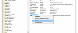
Now we go along the path C:\AVR\my328\default\, find the hex file we created there - my328.hex and flash it into the controller. Choose what to flash (avrdude or uniprof) yourself.
In avrdude it will look like this:
avrdude -c gromov -P com1 -p m328p -U flash:w:\AVR\my328\default\my328.hex ###WIN### avrdude -c gromov -P /dev/ttyS0 -p m328p -U flash: w:my328.hex ###Linux###
Disable the “reset” and see the diode blink once per second. I hope that I have convinced you of the simplicity and convenience of the command line.
To turn the Arduino back into an Arduino, you have a backup.
As already written above, I will not go into explanations of working with AVR Studio, nor will I give lessons on the SI language. Firstly, this was not part of my plans (I just wanted to help make the transition from Arduino to AVR Studio), and secondly, I’m unlikely to be able to do it better than what is written on the website easyelectronics.ru .
Here are links to lessons on MK programming, about fuses, about the design of input/output ports, about botloader and a tutorial on .
In the future, I plan to post various Arduino projects transferred to AVR Studio .
That's all, thank you.
Optimal ESP8266 connection
| Connecting ESP8266 | Note | USB-TTL |
| VCC | Connect ESP8266 to an external power supply >300mA, 3.3V | |
| GND | All GND pins must be connected together: ESP8266, USB-TTL and power supply | GND |
| TX (UTXD) | RX | |
| RX (URXD) | TX | |
| GPIO0 | 10k power pull-up resistor | DTR (if your USB-TTL does not have a DTR pin routed, you will have to manually switch GPIO0 to ground to put the ESP8266 into firmware mode) |
| RESET (RSBT, REST) | 10k power pull-up resistor, you can also add a button connecting RESET and GND to manually reset the module | RTS (if your USB-TTL does not have an RTS pin, you will have to manually reboot the module) |
| CH_PD (CH_EN) | 10k power pull-up resistor | |
| GPIO15 (MTDO) | pull-up resistor 10k to ground (for those modules where the GPIO15 pin is output) | |
| GPIO2 | 10k power pull-up resistor (not shown in the diagram, but recommended to increase stability) | |
| GPIO16 | to successfully exit Deep Sleep mode, you need to connect the ESP8266 GPIO16 and RESET pins through a 470 Ohm resistor (not shown in the diagram) |
Notes.
1. Not all modules have all pins. Before purchasing a module, familiarize yourself with the types of modules and their pinouts.
2. If your USB-TTL converter has CTS and DSR , they will not help you to autoload the firmware, because They work only for entrance.
3. For stable operation, the ESP8266 requires a stabilized power supply of 3.3 volts, a current of more than 250 milliamps. Using power from a USB-TTL converter may result in unstable operation.
Minimum connection ESP8266
Minimum connection ESP8266 (increased stability)
You can read in more detail, with all the details, about connecting the ESP8266 in our article ESP8266 - connecting and updating the firmware
We will need
- AVR development board. Preferably Arduino UNO/Piranha UNO or any other AVR board compatible with Ethernet shield. If your panel uses a large number of variables and/or your sketch uses a large number of libraries, you will need to use a microcontroller-based development board with more static and dynamic memory, such as Arduino MEGA or Piranha ULTRA
- Ethernet shield W5500 (if you are using a shield based on the ENC28J60 chip, you must use a microcontroller-based development board with larger static and dynamic memory, such as Arduino MEGA or Piranha ULTRA, and you must download and install the latest version of the UIPEthernet library and change it in the Ethernet .h to UIPEthernet.h ).
- Wire RJ45-RJ45 category cat5e.
- Router with a free RJ-45 LAN socket.
- Internet connection.