When repairing radio and electrical products, repairing wiring, there is a need to search for contact of current conductors in a place where a short circuit may occur (in this case, resistance = 0), to search for a place of poor contact between conductors (resistance tends to infinity). In this case, you should use a device called an Ohmmeter. Resistance is designated by the letter R and measured in Ohms.
An ohmmeter is a device (battery) with a digital or dial indicator connected in series. Also, an ohmmeter is used to check measuring instruments and measure insulation resistance at elevated voltages. All multimeters and testers have a resistance measurement function.
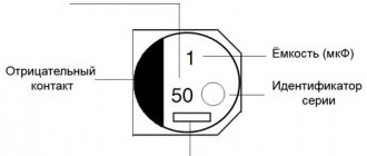
Note! Measure the resistance with the devices completely de-energized so that the ohmmeter does not fail. To do this, remove the plug from the socket or the battery. If the circuit includes capacitors with a large capacity, they should be discharged. Short-circuit the leads of the capacitors through a resistor whose rated current is 100 kOhm for a couple of seconds.
In order to use the Ohm measurement, set the slider on the device to the position that corresponds to the minimum resistance value measurement.
Before taking measurements, check the device for functionality. To do this, connect the ends of the probes to each other.
If this is a tester, you need to set the arrow to o. If that doesn't work, replace the batteries. When checking an incandescent lamp, you can use a device whose batteries are discharged and the needle does not set to zero, but when connecting the probes it deviates from “0”.
If there is a deviation from zero, it means the circuit is intact. Digital instruments have the ability to display readings in tenths of Ohms. If the circuit is open, digital instruments flash overload, and on pointer instruments the arrow tends to “0”.
If the device has a function for testing circuits (diode symbol), it is better to test low-impedance circuits and wires in this way. If the result is positive, a beep will be heard.
Checking incandescent light bulbs
The lamp in the lamp does not light? What is the reason? The failure may be in the socket, switch or electrical wiring. An incandescent, energy-saving, fluorescent lamp is checked by a tester. And this is quite easy to do. To do this, set the slider on the tester to the minimum resistance measurement position and touch the base with the ends of the probes.
The screen shows that the filament resistance is 51 ohms. This means that the lamp is working properly. If the thread were broken, infinite resistance would appear on the screen. A 12V, 100W car lamp shows a resistance of 1.44 ohms. A 220 V and 50 W halogen produces 968 Ohms.
The filament will show less resistance when cooled, when the paw is heated, this figure can increase several times. Therefore, lamps often burn out when turned on. This is because when turned on, the current flowing through the thread exceeds the permissible value several times.
Checking the headphones of the headset
There are problems with headphones associated with loss or distortion of sound, or its complete absence. The reason for this may be a failure of the headphones or the device from which the signal is received.
Using an ohmmeter you can determine the cause of the malfunction. To check the headphones, you need to attach the ends of the probes to the connector through which the headphones are connected to the equipment. Usually this is a 3.5 jack connector. The contact located in the connector closer to the holder is common, figured for the left channel, ring, located between them, for the right.
We bring one end of the probe to the common terminal, and touch the other end alternately to the right and left. The resistance at both ends should be 40 ohms. Often, all the parameters are indicated in the earphone passport.
If the difference in readings is large, there is a short circuit. This is easy to check. It is enough to touch the probes to the left and right channels at the same time. The resistance should increase by 2 times, that is, show 80 Ohms.
It turns out that we are measuring two series-connected circuits. If the resistance changes when you move the wire, the wire is frayed in some place. This usually occurs where the emitters or jack exit. To accurately determine the location of the breakdown, fix the wire, bend it locally, and connect an ohmmeter. If there is a gap where the Jack is installed, you need to buy a collapsible Jack.
You will have to bite off the old one along with part of the frayed wire, solder the contacts to the new connector according to the same principle as they are soldered to the Jack. If a break was found in the headphones, cut off the old piece of wire, solder a new one to the spot where the old solder was.
Resistor value measurement
Resistances (called resistors in a circuit) are widely used in electrical circuits. Often come to check the resistor for serviceability in order to determine the breakdown of the electrical circuit.
In the diagram, the resistor is shown as a rectangle; sometimes there is an inscription inside that may indicate its power. For example, I – 1 W and so on.
To determine the nominal value with an ohmmeter, turn it on in resistance measurement mode. The resistance testing sector is divided into parts. This is done to improve measurement efficiency. For example, the “200” slider indicates that we can measure resistance up to 200 Ohms. “2k” - 2000 Ohms and so on. “k” indicates that you need to add 1000 to the number, since it is a kilo prefix; “M” is mega, therefore the number is multiplied by 1,000,000.
If you set the slider to “2k” measurements and at the same time measure a 300 kOhm resistor, an overload icon will appear on the display. This means you need to set the slider to position 2M. It doesn’t matter in what position it is installed, you can change it during the measurement process.
During resistance measurements, the tester may show other readings than those indicated on the resistor. Such a resistor is not suitable for further use.
Modern resistors are color coded.
Derivation of the formula for the optimal value of reference resistance
If you know the maximum and minimum values of the resistance interval, and want to find the optimal value for the reference resistance, then this can be done using this formula.
This solution is not difficult to obtain by expressing the variables Rref and n from this system of equations. 1023 is a constant equal to the maximum value that the ADC produces. For other ADCs it may be different.
The amount of indentation, i.e. n will be equal to
The point of this n is to accurately fall within the range from Rmin to Rmax, in fact it is better to choose it based on the relative error, and not from the desire to fall into any specific range.
Using the last three equations, you can always calculate which reference resistance to choose.
Knowing n, you can easily find the number of different values in this range. I'll call it capital N.
This is all great, but there is a much simpler way to calculate the reference resistance.
If I need to accurately measure the resistance near a single point, so that the relative error is small, then I will choose Rref equal to this resistance. Then the ADC values will always be near 512, where the relative error is small.
By the way, near the point, Rmax will be equal to Rmin and, as follows from the formula in which Rref is expressed through Rmax and Rmin, all this will be equal to Rref.
In general, all this means is that if you have a thermistor and you want to very accurately measure temperature around a certain value, then you need to measure the resistance of this thermistor near that temperature and take Rref equal to this resistance. Everything above is a mathematical proof of this statement.
But if you now think that you can just as well take the middle of the range that interests you, then you have not understood anything. This is not how range should be calculated.
Checking diodes with a multimeter or tester
If it is necessary to convert alternating current to direct current, semiconductor diodes are used. When checking the board, the first attention should be paid to them. They are made from silicon, germanium and other materials that serve as semiconductors.
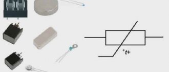
The diodes differ in appearance. The body can be made of plastic, glass, metal. They can be either colored or transparent. Despite this, they all have 2 outputs. In circuits, as a rule, LEDs, zener diodes, and rectifier diodes are used.
Conventionally, they are shown as an arrow that rests on a line segment. The diode is designated by the letters VD and only the LEDs are designated HL. The purpose of the diodes directly depends on the designations that are shown in the drawing. Due to the fact that the circuit may include a huge number of diodes connected in parallel, they are numbered.
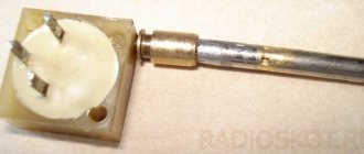
The diode is easy to check if you know its operating principle. And it’s simple, it’s like a nipple. When air enters, the wheel is inflated, but it will not come back out. The same operating principle applies to diodes. Only he passes current through himself. To check its performance, you need a constant power source, which can be an ohmmeter or a tester, since they use batteries.
The photo shows a diagram of how the tester works when checking resistance. The terminals receive voltage of a certain type of polarity. “+” is supplied to the red terminal, “-” to the black terminal. When we touch, it turns out that there will be a positive probe at the anode terminal, and a negative one at the cathode terminal. Current will begin to flow through the diode.
If you mix up the probes, the current will not flow. The diode can be broken, serviceable, or broken. When a breakdown occurs, no matter which direction we connect the probes, current will flow through the diode. This is all because the diode in this case will be a piece of wire.
If a break occurs, no current will flow. It rarely happens that the junction resistance changes. Such a breakdown can be easily identified by looking at the display. Using this principle, you can check the rectifier diode, LED, zener diode, Schottky diode. Diodes can be either with leads or have an SMD design. Let's practice.
First, insert the probes into the device, observing the color markings. COM – black cable, R/V/f – red, plus. Next, set the slider to “dialing”. The photo shows the 2kOm position. We turn on the device, close the probes, and make sure that it works.
First of all, let's check the germanium diode D7. He is already 53 years old. Such diodes are not currently produced, since the price of raw materials is high, and the operating temperature is low (max 80-100). However, they are good because they have low noise and low voltage drop. They are appreciated by people who collect tube audio amplifiers.
When connected directly, the voltage drop is 0.129 mV. The dial gauge will show somewhere around 130 Ohms. If you change the polarity, the multimeter reading will be equal to 1, and the pointer, in turn, will show infinity. This means that the resistance is too great. The diode is OK.
A silicon based diode is tested in the same way. The case has 2 cathode terminals, which are marked with a dot, line or circle. With a direct connection, the drop is about 0.5 V. More powerful diodes will show approximately 0.4 V. Schottky diodes, whose drop is 0.2 V, are tested in this way.
Powerful LEDs have a drop of more than 2 V, the device can show 1. In this case, the LED is an indicator. If it glows, even faintly, then everything is fine.
Some types of higher-power LEDs are made according to the chain principle. That is, they have several LEDs connected in series. This is not visible from the outside. The drop across them can be up to 30 V; they should be checked with a power supply that has the appropriate voltage and resistors included in the circuit.
Classification and principle of operation
Classification
- According to their design, ohmmeters are divided into panel, laboratory and portable
- According to the principle of operation, ohmmeters can be magnetoelectric - with a magnetoelectric meter or magnetoelectric logometer (megaohmmeters) and electronic - analog or digital
Magnetoelectric ohmmeters
The operation of a magnetoelectric ohmmeter is based on measuring the current flowing through the measured resistance at a constant voltage of the power source, using a magnetoelectric microammeter. To measure resistances from hundreds of ohms to several megaohms, a meter (microammeter with additional resistance), a constant voltage source and the measured resistance rx
turn on in series.
In this case, the current strength I
in the meter is equal to:
I = U/(r0 + rx)
, where
U
is the voltage of the power source;
r0
is the resistance of the meter (the sum of the additional resistance and the resistance of the microammeter frame).
According to this formula, a magnetoelectric ohmmeter has a nonlinear scale. In addition, it is reverse (zero resistance value corresponds to the extreme right position of the instrument arrow). Before starting resistance measurement, it is necessary to perform a zero adjustment (adjust the value of r0
) a special regulator on the front panel when the input terminals of the device are closed, to compensate for instability of the power source voltage.
Since the typical value of the total deflection current of magnetoelectric microammeters is 50..200 μA, the supply voltage provided by the built-in battery is sufficient to measure resistances up to several megaohms. Higher measurement limits (tens - hundreds of megaohms) require the use of an external constant voltage source of the order of tens - hundreds of volts.
To obtain a measurement limit of kilo-ohms and hundreds of ohms, it is necessary to reduce the value of r0
and accordingly increase the total deflection current of the meter by adding a shunt.
At small values of rx
(up to several ohms) another circuit is used: the meter and
rx
are connected in parallel.
In this case, the voltage drop across the measured resistance is measured, which, according to Ohm's law, is directly proportional to the resistance (provided I
= const).
- EXAMPLES:
M419, M372, M41070/1
Ratiometric megohmmeters
The basis of ratiometric megaohmmeters is a ratiometer, to the arms of which exemplary internal resistors and the measured resistance are connected in different combinations (depending on the measurement limit), the reading of the ratiometer depends on the ratio of these resistances. As a source of high voltage necessary for carrying out measurements, such devices usually use a mechanical inductor - a manually driven electric generator; in some megohmmeters, a semiconductor voltage converter is used instead of an inductor.
- EXAMPLES:
ES0202, M4100
Analog electronic ohmmeters
The operating principle of electronic ohmmeters is based on converting the measured resistance into a voltage proportional to it using an operational amplifier. The measured object is included in the feedback circuit (linear scale) or at the input of the amplifier.
- EXAMPLES:
E6-13A, F4104-M1
Digital electronic ohmmeters
A digital ohmmeter is a measuring bridge with automatic balancing. Balancing is carried out by a digital control device by selecting precision resistors in the bridge arms, after which the measuring information from the control device is supplied to the display unit.
- EXAMPLES:
OA3201-1, E6-23, Shch34
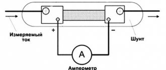
Small resistance measurements. Four-wire connection
When measuring small resistances, an additional error may occur due to the influence of transition resistance at the connection points. To avoid this, use the so-called. four-wire connection method. The essence of the method is that two pairs of wires are used: one pair supplies a given current to the object being measured, and the other pair measures the voltage on the object, proportional to the current strength and resistance of the object. The wires are connected to the terminals of the two-terminal network being measured in such a way that each of the current wires does not directly touch the corresponding voltage wire, and it turns out that the transition resistances at the contact points are not included in the measuring circuit.
Measurement methods
Using an ohmmeter is not difficult. They are available in two types - with parallel and serial connection to the measured circuit. There are also universal versions of devices, the type of connection in which is set by a selector.
To start measurements, use the handles or control keys to set the depth of the values being studied, including micro-, milli-, kilo-, mega-, or ordinary Ohms. In magnetoelectric devices, the indicator is set to “0”; for the rest, the stage is skipped. An ohmmeter is connected to the circuit under test, according to its type - in series or in parallel. The final resistance values will be displayed on the scale or screen of the device.
All of the above is true for conventional meters. But, there is a subclass of ohmmeters that are designed to conduct research on dielectric materials. For example, cable protective sheaths or wire insulation. Working with them is a little different, at least in that the test is performed not on a closed circuit, but in two different conductors, separated by a layer of material whose characteristics need to be determined. A good example here would be the insulated cores of a classic cable. Resistance to breakdown between which is checked by both the manufacturer and the end user of high-voltage current transmission lines.
Ohmmeters designed to measure megaohms often have a third contact, to which the shield of the insulated wire is connected.
The procedure itself, for high-voltage devices, takes a certain time, specified in the performance characteristics of the material being tested. During the entire test period, the insulation resistance value should not change.
The generation of the current required for measurements can be done by rotating the handle brought out by human force, by a third-party power source, or by converting the internal energy of the device into an increased form. Megaohmmeters are often equipped with a timer that shows the time period for completing the test.
Names and designations
Species names
- Microohmmeter
- ohmmeter with the ability to measure very low resistances (less than 1 mOhm) - Milliohmmeter
- ohmmeter for measuring small resistances (units - hundreds of milliohms) - Megaohmmeter
(
old
megohmmeter) - ohmmeter for measuring high resistances (units - hundreds of megaohms) - Teraohmmeter
- ohmmeter for measuring very high resistances (units - hundreds of teraohms) - Ground resistance meter
- a special ohmmeter for measuring transient resistance in grounding devices
Designations
Ohmmeters are designated either depending on the system (basic operating principle) or according to GOST 15094
- M
xx - devices of the magnetoelectric system - F
xx,
Shch
xx - electronic system devices - E6-
xx - resistance meters, marking according to GOST 15094
Top best on the market
An ohmmeter is a device that measures the resistance of a section of a circuit, or a specific element. It can be either a separate device or part of multifunctional measuring equipment. In the presented TOP, all options will be considered based on the demand for models on the market, according to information, specialized media and personal customer reviews.
Megaohmmeters
| Model | Type | Measurement limits (MΩ) | Voltage measurements (V) | Error | Type of current boosting source | Additional features | Price, rub) |
| MEGEON 13125 | Digital | 0–49900 | 2500 | 10% | AA Battery Energy Converter | AC voltage measurement 30–600 V | 8980 |
| MEGEON 13500 | Analog | 0.1–2500 | 1 % | Lever | No | 10569 | |
| MEGEON 131100 | Digital | 0.1–2000 | 4 % | AA Battery Energy Converter | Determination of DC and AC voltage | 6890 | |
| UNI-T UT511 | Digital | 0.1–2000 | 1000 | 2–3 % | AA Battery Energy Converter | Analog bar graph, screen backlight, timer, result storage, logging (18 readings), advanced calculations | 9269 |
| Radio Service E6-32 | Digital | 1–10000, 10000–99900 100000–300000 | 50–2500 | 3 %, 5 %, 15% | AA battery energy converter, power supply | Log (10,000 readings), save 100 settings, communicate with PC via Bluetooth | 28710 |
Among the megaohmmeters mentioned in the table, the Radio Service E6-32 seems to be the best in terms of characteristics, capabilities and case protection, despite its high price.
Specialized ohmmeters
| Model | Type | Measurement limits | Error | Additional features | Price, rub) |
| UNI-T UT522 | Digital | 0.004 MOhm | 5 % | Hold test results, voltage measurement | 13190 |
| RGK RT-25 | -//- | 20000 MOhm | 3 % | No | 9900 |
| CEM DT-5500 | -//- | 2000 MOhm | 3.5 % | Fixing (Hold) test results, measuring AC voltage up to 750 V and DC up to 1000 V | 12100 |
| SEW 1800IN | Analog | 200 MOhm | 5 % | Measure AC voltage up to 600 V | 12150 |
| HR390 | Digital | 120 Ohm–1 MOhm | <1 % | Capacitor capacitance measurement and display backlight available | 3600 |
Some models on the list are capable of taking on the functions of megohmmeters (dielectric resistance meters). The best, in terms of capabilities, for measuring the resistance of circuit sections, here would be the GEM DT-5500.
Multimeters
| Characteristic | RESANTA DT 838 | RGK DM-10 | ELITECH MM 300 | Tesla DT832 | Mastech MY-68 |
| AC voltage measurement | 200–750 V | 200–600 V | 20–750 V | 200–750 V | 200–750 V |
| AC voltage error | 1.2 % | 1.2 % | 1.2 % | 1.2 % | 1.2 % |
| AC Current Determination | No | No | Up to 20 A | No | Up to 10 A |
| DC voltage measurement | 200 mV–1000 V | 20 mV–600 V | 200 mV–1000 V | 200 mV–1000 V | 20 mV–600 V |
| DC voltage error | 0.5 % | 0.5 % | 0.5 % | 0.5 % | 0.5 % |
| DC Current Determination | 2000 μA–10 A | 2000 μA–10 A | 20 μA–20 A | 2000 μA–10 A | 2000 μA–10 A |
| DC current error | 1 % | 2 % | 2 % | 1 % | 2 % |
| Resistance Sensitivity | 200 Ohm–2000 kOhm | 200 Ohm–20 MOhm | 200 ohm–200 megohm | 200 Ohm–2000 kOhm | 200 Ohm–32.6 MOhm |
| Resistance value error | 1 % | 1 % | 1 % | 1 % | 1 % |
| Calling | Eat | Eat | Eat | Eat | Eat |
| Sound signal | Eat | Eat | No | Eat | Eat |
| Checking transistors | Eat | Eat | Eat | Eat | Eat |
| Temperature sample | ºC | ºF and ºC | ºC | No | No |
| Frequency measurement | No | No | Up to 10 Hz | Up to 10Hz | Up to 10 Hz |
| Determination of capacitance of capacitors | No | No | Up to 20 μF | No | 32.6 μF |
| Hold | No | Eat | Eat | No | Eat |
| Backlight | No | Eat | No | No | No |
| Additionally | No | No | Separate power button | No | Auto selection of measurement depth |
| Price, rub) | 640 | 1190 | 890 | 429 | 2888 |
Here the devices are universal, and determine not only the resistance, but also most of the characteristics of the circuits that an electronics engineer needs to know. All presented multimeters are digital. In the list, the most interesting and functionally complete model can be called ELITECH MM 300. An inexpensive device, with many additional features and good accuracy.
Other resistance measuring instruments
DC resistance measurement
- Measuring bridge
- provides very high accuracy, but is inconvenient due to the need for manual balancing - Resistance store
,
electrical resistance coils
- measurement is carried out by comparison method, using substitution of the measured object - Multimeter (tester)
- a combined device for measuring voltage, current and resistance
AC resistance measurement
- Immittance meter
- resistance measurements at frequencies from tens of hertz to several megahertz - High-frequency (vector) impedance meter
- resistance measurements at frequencies of hundreds of kilohertz - hundreds of megahertz - Q meter
- indirect resistance measurements at frequencies from 1 kHz to several hundred megahertz - Impedance meter
- measuring line load resistance at frequencies of tens - hundreds of megahertz - Measuring line
- measuring line load resistance at frequencies of hundreds - thousands of megahertz
Suppression of radio interference at the ADC input
The input signal often contains high frequency noise. Therefore, it is better to connect a low-pass filter (LPF) at the input. It filters out interference above a certain frequency.
The cutoff frequency is calculated as follows
f — Cutoff frequency, Hz
R — Resistor resistance, Ohm
C — Capacitance of the capacitor, F (Farads)
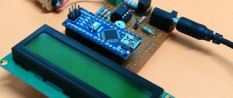
For example, if the capacitance of the capacitor is 10 microfarads, the resistance of the resistor is 1 kilo-ohm, then the cutoff frequency will be 16 hertz.
You can also reduce noise programmatically. For example, instead of taking one measurement, you can take dozens of measurements in a row and then calculate the average. It is better to select the number of measurements and the pause between them experimentally.
Literature and documentation
Literature
- Handbook of Electrical Measuring Instruments
; Ed. K. K. Ilyunina - L.: Energoatomizdat, 1983 - Handbook of radio measuring instruments
: In 3 volumes; Ed. V. S. Nasonova - M.: Sov. radio, 1979 - Handbook of Electrical Measuring Instruments
; Ed. K. K. Ilyunina - L., 1973
Regulatory and technical documentation
- GOST 22261-94 “Instruments for measuring electrical and magnetic quantities. General technical conditions"
- GOST 23706-93
- GOST 8.366-79 “State system for ensuring the uniformity of measurements. Digital ohmmeters. Methods and means of verification"
- GOST 8.409-81 “State system for ensuring the uniformity of measurements. Ohmmeters. Methods and means of verification"
Types of electrical measuring instruments
Classification of electrical measuring instruments:
- variable;
- permanent;
- combined devices.
By level of accuracy:
Each number indicates a percentage of the permissible error.
According to the essence of the work:
- electromagnetic;
- induction;
- magnetoelectric;
- ferromagnetic.
When carrying out measurement tests, it is necessary to select the appropriate measuring device correctly.
- Ammeters are devices for measuring current values. The unit of measurement is Ampere (A).
- Voltmeter – measures the voltage of the electrical network. The unit of measurement is Volt (V).
- An ohmmeter is an auxiliary device that measures resistance in an electrical circuit. Measured in Ohms (Ohm).
- A wattmeter is an element that measures network power. The unit measured is Watt (W).
- Frequency meter – a frequency meter for alternating pulse values. Measured in Hertz (Hz).
see also
- Electrical resistance
- Measuring bridge
- Resistance Shop
- Imitance meter
- Q meter
- Impedance meter
- Measuring device
- Radio measuring instruments
- Electrical measuring instruments
- Unplug and turn off the power to the circuit under test.
To ensure measurement accuracy, as well as your own safety, the wire or circuit must be completely de-energized. Your ohmmeter will provide voltage and current to the circuit, so there is no need for other power sources. According to the ohmmeter/voltmeter instructions, testing a circuit while power is present “can cause damage to the meter, the circuit, and you.”
- Choose the right ohmmeter for your project.
Analog ohmmeters are very easy to use and inexpensive. Their measuring range is from 0-10 to 0-10,000 ohms. Digital analogues have the same range or "auto-ranging", so they can measure the resistance of a device or circuit and automatically select the appropriate range.
- Check the ohmmeter for battery presence.
If you just recently purchased an ohmmeter, the battery may already be installed in the meter or packaged separately along with installation instructions.
- Insert the probes into the connectors on the device.
For multi-function appliances, you will see a "common" or negative probe, as well as a "positive" probe. They also come in different colors, red (+) and black (-).
- Zero the instrument if it has a zero dial.
Note that the scale moves in the opposite direction of most conventional measuring scales, meaning more resistance on the right and less resistance on the left. Zero resistance will be observed when connecting two probes to each other. You can adjust the meter by holding the probes together and turning the dial until the needle on the scale reads 0 ohms.
- Select the circuit or electrical device you want to test.
To practice, you can take almost anything that conducts electricity, from a piece of aluminum foil to a pencil mark on paper. To get an idea of the accuracy of your measurements, go to an electronics store and buy several different resistors or devices with a known resistance level.
- Touch one probe to one edge of the circuit, and the other to the other edge and look at the indicators of the device.
If you purchased a 100 ohm resistor, you can touch each wire on the resistor with a probe, select the 1000 or 10,000 ohm range, and read the meter to make sure it actually reads 1000 ohms.
- Isolate components in a heavy-duty electrical circuit to test them separately from each other.
If you are reading ohms across a resistor in a PCB, you will have to unsolder or chip off the resistor to be sure you are not getting a false reading from another part of the circuit.
- Measure the resistance of the wires or circuit line to check for a short or open open in the circuit.
If you get an "infinite resistance" reading, it means there is nowhere for the electrical current to go. Simply put, this indicates a burned out component somewhere in the circuit or a broken conductor. Since most circuits contain "output" devices (transistors and semiconductors), diodes and capacitors, you may not be able to measure continuity even if the circuit is completely intact. This is why it is very difficult to test a circuit with just an ohmmeter.
- If you are not using the ohmmeter, turn it off.
Sometimes, while storing the device, the wires can become shorted and cut off power to the battery.