Hello, dear readers of the site. Today we will look at practical circuits for connecting incandescent lamps in series and parallel
In the article about connection diagrams for three or more lamps, I talked about a parallel connection, but I missed the serial connection. In this article we will look at both types of connections used in everyday life.
Let's go from simple to complex. An ordinary lamp on circuit diagrams is designated as follows:
The next point you must understand
and
remember
:
Connecting wires in the diagrams are shown as lines
.
The junctions of three or more wires are shown with dots
, and if the wires intersect without a connection, then a dot is not placed at the place of their intersection.
The picture below shows when the wires simply cross
, that is, they pass side by side and do not touch each other, and when the wires are already
connected to each other
, this is indicated by
the point
at the intersection.
Now let's look at the types of connections:
Serial connection diagram
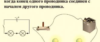
First, let's look at the simplest assembly of two incandescent light bulbs connected in series.
We have:
- two lamps screwed into sockets
- two power wires coming out of the sockets
What does it take to connect them in series? There is nothing complicated here.
Simply take either end of the wire from each lamp and twist them together.
You need to apply 220 Volts (phase and zero) to the two remaining ends.
How would such a scheme work? When a phase is applied to the wire, it passes through the filament of one lamp and, through twisting, reaches the second lamp. And then it meets zero.
Why is such a simple connection practically not used in apartments and houses? This is explained by the fact that the lamps in this case will burn at less than full intensity.
In this case, the voltage will be distributed evenly across them. For example, if these are ordinary 100-watt light bulbs with an operating voltage of 220 volts, then each of them will receive plus or minus 110 volts.
1 of 2
Accordingly, they will shine at less than half of their original power.
Roughly speaking, if you connect two lamps of 100 W each in parallel, you will end up with a lamp with a power of 200 W. And if the same circuit is assembled in series, then the total power of the lamp will be much less than the power of just one light bulb.
Here is the result of measuring the current strength of such an assembly at an actual supply voltage of 240V.
Based on the calculation formula, we find that two light bulbs shine with a power equal to only: P=I*U=69.6W
At the same time, the decrease in brightness will be uniform only if you have the same power bulbs.
If they differ, say one of them is 60W, and the other is 40W, then the voltage across them will be distributed differently.
1 of 2
What does this give us in a practical sense when implementing these schemes?
Preparing for work
Decide on the type of outlet
There is a huge variety of electrical outlets that differ in purpose, type of design, installation method and the presence of additional functions. In this case, we will consider sockets used in Russia and designed for 220 V.
Depending on the type, the method of installing sockets differs.
Soviet-style socket, without grounding. This type of socket is intended for electrical appliances whose housing does not require grounding. Their main disadvantage, in addition to the lack of grounding, is that the plugs of modern electrical appliances simply do not fit into the sockets due to the difference in diameters and the presence of side protrusions. Therefore, only old-style or low-power electrical appliances with the appropriate type of plug can be connected to this outlet. "Euro socket" with grounding. Suitable for all modern electrical appliances
Main advantages: tight contact, there is an additional contact for connecting the ground wire, which is very important to eliminate the risk of electric shock for electrical appliances such as a washing machine, refrigerator, electric stove, water boiler. Socket for electric stove
As the name suggests, this type of socket is installed to connect an electric stove
This is a power outlet that can withstand connected power up to 7 kW or more. Internal socket. Installed in a special box installed in a recess in the wall. Used for hidden electrical wiring. External (surface) socket. It is mainly used in rooms with external electrical wiring.
Selecting a connection diagram
If we are not talking about replacing an old outlet, but about installing a new one, you will have to choose the optimal connection scheme.
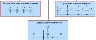
The following schemes exist:
- Parallel connection. With this scheme, a separate wire from the junction box goes to each outlet. Used to connect high power electrical appliances.
- Serial connection. All sockets are connected one after another to one wire. It is preferable when connecting low-power devices to these sockets.
- Mixed connection when using both circuits at the same time (some sockets are connected in series, some in parallel).
Diagram of serial connection of sockets
Power outage
Before starting any electrical work, including installing a socket, you must turn off the power supply by unscrewing the plugs/turning off the circuit breakers and using an indicator screwdriver, make sure there is no voltage.
Which light bulb will shine brighter and why?
A lamp whose filament has greater resistance will burn better and brighter.
Take for example light bulbs that are radically different in power - 25W and 200W - and connect them in series.
Which one will glow at almost full intensity? The one with P=25W.
The resistivity of its tungsten filament is significantly greater than that of two hundred, and therefore the voltage drop across it is comparable to the voltage in the network. With a series connection, the current will be the same in any part of the circuit.
At the same time, the amount of current that can ignite 25 watts is in no way capable of “setting fire” to two hundred. Roughly speaking, a light source with a lamp of 200W or more will be perceived relative to 25W as an ordinary section of wire through which current flows.
You can increase the number of lamps and add one more to the circuit. This is done again very simply.
Twist the two ends of the power wire of the third lamp with any ends from the first two. And to the remaining ones you again supply 220V.
1 of 2
How will this garland glow in this case? The voltage drop will be even greater, which means the light bulbs will not only light up at half power, but will barely burn at all.
Soft start device (UPVL) for incandescent lamps 220V and 12V
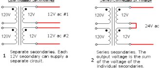
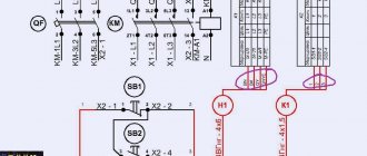
Today, a large number of different UPVL models are produced, which differ in function, cost and quality. The device, which is sold in specialized stores, is connected in series to a 220 V light source. We can see the circuit and appearance of the device in the photo below.
Scheme of a soft switching device for 220 V lamps
If the power supply for the lamps is 12 or 24 V, then the device must be connected in front of the step-down transformer, also in series with the initial primary winding.
The device must correspond to the load that will be connected with a certain margin. To do this, you need to calculate the number of lamps and their total power.
Since the device is small in size, the UPVL can be placed under a chandelier, in a socket box or in a connection box.
Disadvantages of the scheme
In addition to the significant voltage drop, the second negative aspect of such a circuit is its unreliability.
If just one of the light bulbs in this chain burns out, then all the others will immediately go out.
It is also necessary to make a remark that such a sequential circuit will work well on ordinary incandescent lamps. On some other types, including LED ones, you may not expect any effect.
They may have an electronic circuit in their design that requires power of about 220V. Of course, they can operate at lower values of 150-160V, but 90V or less will no longer be enough for them.
Installation features
To correctly connect spotlights, you need not only to choose the right circuit. It is necessary to follow a certain sequence of actions, which depends on the type of ceiling.
You just need to connect a few spotlights - and you have a beautiful interior
In suspended ceilings
Spotlights are usually installed with suspended or suspended ceilings. If the ceilings are suspended, all wires are laid in advance. They are attached to the ceiling without connecting to power, the lamps are placed and secured on pendants, then the wires are connected to them and the operation is checked.
Prepared for installation of suspended ceilings
Before installing suspended ceilings, turn off the power, remove the lamps and remove parts that may be damaged by temperature. After installing suspended ceilings, holes are cut in the material (the lamps are visible or can be felt), sealing rings are installed, and then the lamps are assembled.
In plasterboard ceilings
If the ceiling is made of plasterboard, you can proceed according to the same scheme, but the lamps must be installed after the ceiling has been plastered. That is, separate the wiring and leave the ends of the wiring hanging freely. To avoid problems with determining the location of lighting fixtures, it is necessary to draw a detailed plan indicating the exact distances from the walls and from each other. According to this plan, markings are made and holes are cut out using a drill with a crown of the appropriate size. Since there may be small movements - a few centimeters - when cutting the cable, leave a margin of 15-20 cm. This will be quite enough (but do not forget that the wires are attached to the main ceiling and they should extend 7-10 cm beyond the level of the drywall. If the ends turn out to be too long, you can always shorten them, but extending them is a big problem.
If you need to install a converter
There is a second way to connect spotlights to a plasterboard ceiling. It is used if there are few light sources - four to six pieces. The entire installation of spotlights along with wiring is done after the work on the ceiling has been completed. Before installation begins, the cable/cables from the junction box are led beyond the ceiling level. After finishing the puttying and sanding work, markings are made and holes are drilled. The cable is passed through them, bringing the ends out. Then the lamps themselves are installed.
Everything is simple, but this method cannot be called correct: the cables simply lie on the drywall, which definitely does not comply with fire safety standards. You can still turn a blind eye to this if the ceiling is concrete, the cable is non-flammable, the cross-section of the wire is not small, and the connection of the wires is done correctly.
Sequence of work in photo format
If the floors are wooden, the PUE requires installation in non-flammable all-metal trays (cable ducts) or metal pipes. You can install such wiring only before starting work on the ceiling. It is very undesirable to violate installation rules - wood, electricity, heat generation during operation... not the safest combination.
Errors when assembling the circuit and connecting the switch
By the way, some electricians, when installing lighting in an apartment, may make an accidental mistake, which is precisely related to the serial connection of lighting sources.
As a result, you will experience the following effect. When you turn on the light switch, one light bulb in the room will light up, and when you turn it off, another light will come on.
1 of 2
In this case, it will be impossible to ensure that both go out at once. How is this possible?
The mistake lies in the fact that the electrician simply mixed up the connection location of one of the switch wires and stuck it into the gap between two lamps of different power. Here is a visual diagram of such an incorrect assembly.
As can be seen from it, when the voltage is turned on, a voltage of 220V is supplied through the contacts of the one-key player to the second lighting source, and it lights up as expected.
In this case, the first source remains without power, because the “eponymous” building is connected to it on both sides.
And when you break the circuit, the same sequential circuit is already formed here and the lamp of lower power will glow.
While the larger one will practically go out. Everything is as described above.
Plasterboard ceilings
The connection diagram for lamps in a suspended ceiling looks similar, but installation begins only after applying a layer of putty. First, a plan for the location of the lamps is drawn on paper with the exact distance from the walls and from each other. Next, the electrical wires are laid out, fixing them to the main ceiling, and leaving the ends hanging freely. Moreover, it is best to leave the ends with a small margin, approximately 15-20 cm.
In general, the wire should hang below the plasterboard structure by about 10 cm. The fact is that it is very difficult to increase a short wire in an unforeseen situation, but the length can always be reduced. In accordance with the drawing, marks are made on the ceiling and holes are cut using a drill with an installed crown corresponding to the size of the hole for the spotlight. Install lamps into the resulting holes, connect the wires and check the operation of the lighting.
There is another diagram for connecting spotlights on a plasterboard structure. It is used when the number of light sources does not exceed 6 units.
The connection process is carried out according to the following scheme:
- Electrical wires are pulled from the junction box to the location of the lamps.
- Next, install the plasterboard structure and rough finishing work, in particular puttying and sanding.
- Holes are cut out in the ceiling into which spotlights are inserted during further installation work.
- Bring the ends of the laid cable out and connect the lighting devices.
This method allows you to quickly and easily find a solution to the question of how to connect a spotlight. However, it does not fully comply with fire codes and requirements, since in this case the wires end up simply lying on the plasterboard ceiling. The problem can be solved by using a non-flammable cable with a large wire cross-section, provided that it is installed correctly and there is a concrete base floor.
You can use this method when connecting spotlights on the ceiling with a wooden base ceiling. However, installation in metal pipes or non-flammable all-metal cable channels is required here.
It is important to carry out installation work on laying electrical wires before directly installing the plasterboard sheet. You should not deviate from the listed rules, since the combination of wood, electricity and the operation of lighting devices, accompanied by the release of heat, can be called quite dangerous
Use in everyday life
Where can you apply such a seemingly impractical scheme in everyday life?
The most widely known use of such structures is Christmas tree garlands.
You can also make consistent lighting in a long passage corridor and get loft-style lighting without much expense.
Are the light bulbs in your hallway or home constantly burning due to high voltage? The cheapest way out is to connect another one in series.
Instead of one 60W, you turn on two hundred parts and use them almost “forever”. Due to the reduced voltage of 110V, the likelihood of their failure is reduced hundreds of times.
Another original application, which I still do not recommend using, but some electricians resort to it in desperate situations. This is the so-called phasing of three-phase circuits.
Physical parameters
An important step when connecting halogen, LED or fluorescent lamps is physical data. The main parameter for all lamps can be considered ohmic resistance, on the basis of which power consumption is calculated.
For example, consider the option of connecting lighting devices as a classic resistive load:
Rice. 3. Parallel connection of resistive load
So the same filaments represent a purely resistive load, so we will calculate them as the sum of resistors R1 - R3. For parallel circuits, the total resistance of all devices is calculated based on the ratio:
1/Rtotal = 1/R1 + 1/R2 + 1/R3
After transformation, the expression will look like:
A similar calculation is made for the inclusion of fluorescent and LED lamps. Note that in calculations under ideal conditions the resistance of the connecting wires is neglected. This technique is also relevant for most lighting devices, since the value is disproportionately smaller. However, in the case of calculating low-current lamps or LEDs, the resistance of the wires cannot always be neglected, so they are also included in the calculations.
How to phasing inputs with incandescent light bulbs
Let's say you need to connect two three-phase (380V) inputs in parallel with each other, from the same power source. You don’t have a voltmeter, multimeter or tester at hand. What to do?
After all, if you mix up the phases, you can easily create a phase-to-phase short circuit! And here again, a sequential assembly of just two light bulbs will help you.
Assemble them according to the very first diagram given and connect one end of the power wire to input phase No. 1, and with the other end touch the wires of input No. 2 one by one.
With phases of the same name, the lamps will not light up (for example, fA input No. 1 - fA input No. 2).
And if they are different (fA input No. 1 - fV input No. 2) - they will light up.
You would never succeed in such an experiment with only one lamp, since it would instantly explode from the increased voltage for it of 380V. And in a series assembly with two products of the same power, the voltage will be applied to them within normal limits.
But the best and most practical application is to use this circuit not for lighting at all, but for heating. That is, your light sources will primarily work not as lamps, but as heaters.
How to make such a simple and uncomplicated infrared stove, read the article at the link below.
Something similar is often used in incubators.
Pros and cons of parallel connection
Pros:
- if one element fails, the rest will continue to work;
- the circuit gives the brightest light possible, since full voltage is supplied to each device;
- You can remove as many wires as you like from one lamp to connect additional loads (you will need one zero and a specific number of phases);
- Suitable for energy-saving electrical devices.
Connection diagram of an energy-saving lamp to electronic ballasts.
There are practically no disadvantages, except for the large number of conductors in a branched system with many lamps.
Online calculator for calculating a resistor
| Connection type: | |
| Supply voltage: | Volt |
| LED forward voltage: | Volt |
| Current through LED: | Milliamp |
| Number of LEDs: | PC. |
| Results: | |
| Exact resistor value: | Ohm |
| Standard resistor value: | Ohm |
| Minimum resistor power: | Watt |
| Total power consumption: | Watt |
Nuances of twist formation
Options for connecting wires by twisting
When making a configuration from a pair of wires, their exposed ends are laid crosswise. The intersection point should be located near the place where the insulation begins. After this, the ends are squeezed with your fingers and twisted. Finally, squeeze with pliers.
If the number of wires being connected is more than two, they are worked according to the same principle. If the configuration turns out to be long, it can be folded in half and pressed with a tool so that less insulating tape is required for processing. The latter begins to be laid from the lower edge of the insulation and goes down. Having reached the ends of the bare tails, they make 2 additional turns “in reserve,” bend it into a twist to protect it, and wind the second row from bottom to top. A few turns should definitely cover the factory insulation.
Basic theoretical issues
Current-voltage characteristic (abbr. VAC) is a graph displaying the dependence of the amount of current flowing through any device on the voltage applied to it. A simple and very capacious characteristic for the analysis of nonlinear components. With its help, you can select operating modes and determine the characteristics of the power source for the device.
Take a look at an example of linear and nonlinear I-V curves.
Graph number 1 in the figure displays the linear dependence of current on voltage, which is what all resistive devices have, for example:
- Incandescent lamp;
- heater;
- resistor (resistance);
Graph number 2 is the current-voltage characteristic characteristic of pn junctions of diodes, transistors and diodes.