Operating principle, classic circuit and difference from the power supply
Even though a driver is often called a power supply, there is a difference between the two concepts. The driver is a source of current that maintains its constant value for passing through the LED, and the power supply maintains a stable voltage.
Let's look at how the power supply works using a specific example:
- Let's connect a resistance (R) of 40 Ohms to a 12 V source.
- Let a current (I) of 300 mA flow through the resistor. When installing two resistors, the current will double and become 600 mA. In this case, the voltage will not change, since it has a proportional relationship with current and resistance (Ohm's law I=U/R).
Now let's see how the driver works:
- Let a circuit with a 225 mA driver include a resistance (R) of 30 Ohms.
- If, at a voltage (U) of 12 V, two 30 Ohm resistors are connected in parallel, the current will remain the same - 225 mA, and the voltage will become half as much - 6 V.
The driver ultimately provides the load with the specified output current regardless of voltage surges. Therefore, LEDs supplied with a voltage of 6 V will shine as brightly as with a source of 10 V, if a given current level is supplied to it.
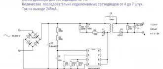
Driver circuit for LEDs:
The driver circuit consists of three interconnected nodes:
- capacitance for voltage separation;
- rectifier module;
- stabilizer.
The principle of operation of the circuit:
- When current passes, capacitor C charges until it is fully charged. The smaller its capacity, the faster it will charge.
- Alternating current is converted into pulsating current. The first part of the wave is smoothed when passing through capacitor C.
- The electrolytic capacitor that completes the circuit serves as a smoothing filter-stabilizer.
Making a driver for LEDs with your own hands
If the user has several semiconductor crystals or a backlight line from an old TV, he can independently make a current source for them.
To do this, you should purchase devices and parts or remove radio elements from old equipment. Often the efficiency of self-made devices is much higher than that of industrial designs.
Materials and tools for work
For a homemade simple driver you will need:
- capacitors: simple 0.27 uF at 400 V and 2 electrolytic 500×16 V and 100×16 V;
- resistor 500 kOhm at 0.5 W;
- 4 diodes or a ready-made bridge for 220 V;
- LM317 chip;
- soldering iron with a power of 20-40 W;
- flux and solder (preferably POS type);
- pliers, wire cutters, pliers;.
- multi-core insulated copper conductors with a cross section of 0.35-1 mm²;
- heat shrink tube;
- multimeter or tester;
- insulating tape;
- board for desoldering elements.
Simple driver circuits for a 1 W LED and a powerful one
A classic converter is a combination of an electronic voltage divider and a stabilizer chip. The first node consists of 2 elements (a 0.27 μF capacitor and a 500 kOhm resistor) connected in parallel, to which a bridge of diodes that can withstand the input voltage is connected in series.
To smooth out pulsations, install 2 “electrolytes”. The first of them 500×16 V is soldered immediately after the bridge. Then a current stabilizer is installed. Behind it is a second capacitor 100×16 V.
The L7812 chip is often used as a stabilizer, but this is not entirely the right solution. It is a linear voltage regulating device and can burn out if the current changes.
Connection diagram
It is better to use LM317, LM338 or LM350 microcircuits, which have protection against short circuits and overheating. They can be powered with any voltage 5-35 V. 5-10 LEDs can be connected to the driver.
The connection diagram is simple:
- the plus of the divider goes to the input of the microcircuit (1 output);
- the common wire through the anode of the LED goes to the minus of the radio component (middle leg);
- The LM317 output (pin 3) is also connected there through a current-limiting resistor.
By installing an adjustable resistance instead of the last element, you can change the current strength, i.e., the brightness of the LEDs within certain limits.
If you need to build a powerful spotlight, then the driver will have to be modified:
- it is necessary to increase the supply voltage to 24 V;
- install a stabilizer with the highest current, and of the proposed microcircuits, only LM338 can output 5A.
Due to the high current, it should be installed on a radiator.
How to assemble and configure the driver?
A simple LED converter has few elements. The driver can be assembled on a special board, a piece of plywood, or mounted.
The device does not require adjustment if you take all the specified parts. The main thing is to correctly calculate the current limiting resistor.
Specifications
When purchasing an LED lamp, you may need to purchase a driver if the lighting device does not have a current converter.
Main characteristics:
- output current, A;
- operating power, W;
- output voltage, V.
The output voltage may vary. It depends on the power connection diagram and the number of LEDs. The brightness level and power depend on the current value.
To ensure that the diodes shine brightly and do not dim, the current at the driver output is maintained at a given level. The power of the converter should be slightly higher than the total number of W of all diodes.
To calculate the driver power, use the formula: P = P (led) × X where:
- P (led) is the power of one LED;
- X – number of diodes.
If the calculated power is 10 W, the driver must be taken with a margin of 20-30%.
The concept of a network driver and its purpose
A driver is an electronic component that receives AC voltage, stabilizes it, and outputs DC voltage. It is important to understand here that we are talking about receiving current. To convert voltage, conventional power supplies are used (the value of the output voltage is indicated on the case). Power supplies are operated in diode strips.
The main characteristic of the converter for LED lighting devices is the output current. Auxiliary LED diodes or other semiconductors are used for the load. Almost always, the driver is powered from a 220 V industrial network, and the output voltage range starts from 2 - 3 and ends in tens of volts. To connect three 3 W LEDs, you need an electronic driver with an output voltage of 9 - 21 V and a current of 780 mA. At light loads, the universal device is characterized by a low coefficient of performance (COP).
To power vehicle headlights, a source with a constant voltage of 10 to 35 V is used. If the power is low, a driver is not necessary, but an appropriate resistor will be required. This component is an indispensable part of a household switch, but when switching an LED diode to a 220 V AC network, you cannot count on reliable and durable operation.
Types of drivers
All drivers are distinguished according to three criteria - the method of stabilization, design features and the presence/absence of protection. Let's consider all the options in more detail.
Linear and pulse
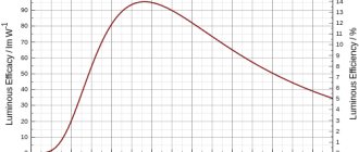
Depending on the current stabilization circuit, drivers are divided into two types - linear and pulsed. They differ in operating principle and efficiency.
The electronic driver circuit is tasked with ensuring stable values of current and voltage supplied to the crystal (LED). The simplest and cheapest option is to include a limiting resistor in the circuit.
Linear power circuit:
This elementary circuit is not capable of automatically maintaining current. As the voltage increases, it increases proportionally and, when it exceeds the permissible value, the crystal will collapse from overheating.
More complex control is carried out by connecting a transistor to the circuit. The disadvantage of a linear circuit is that the power decreases as the voltage increases. This option is acceptable when operating low-power LED sources, but when operating high-power LEDs, such circuits are not used.
Advantages of a linear circuit:
- simplicity;
- cheapness;
- relative reliability.
Along with linear circuits, current and voltage can be stabilized by pulse stabilization:
- after pressing the button, the capacitor is charged;
- after being released, the capacitor discharges, releasing the stored energy to the semiconductor element (LED), which begins to emit light;
- if the voltage increases, the charging time of the capacitor decreases; if it decreases, it increases.
The user does not have to press a button - the electronics do everything for him. The role of the push-button mechanism in modern power supplies is performed by semiconductors - thyristors or transistors.
The considered operating principle is called pulse width modulation in electronics. Tens and even thousands of operations can occur per second. The efficiency of such a scheme reaches 95%.
Simplified pulse stabilization scheme:
Electronic, dimmable and capacitor-based
The scope of its application and performance characteristics depend on the principle of the driver design.
Types of drivers by device principle:
- Electronic. Their circuits necessarily use a transistor. A capacitor is installed at the output, eliminating or at least smoothing out current ripples. Electronic converters are capable of stabilizing currents up to 750 mA. Electronic drivers fight not only ripples, but also electromagnetic high-frequency interference induced by electrical appliances (radio, TV, router, etc.). The presence of a special ceramic capacitor allows you to minimize interference. The downside of the electronic driver is its high cost, but the plus is that the efficiency is close to 95%. They are used in powerful LED lamps: car headlights, floodlights, street lamps.
- Dimmable. A special feature of dimmable drivers is the ability to control the brightness of the lamp. The adjustment is based on a change in the output current, which determines the brightness of the light flux. The driver can be included in the circuit in two ways: between the lamp and the stabilizer or between the power source and the converter.
- Based on capacitors. These are inexpensive models used for budget LED lamps. If the manufacturer did not provide a smoothing capacitor in the circuit, then ripple is observed at the output. Another disadvantage is insufficient security. The advantage of such models is their high efficiency, tending to 100%, and the simplicity of the circuit. Such drivers are easy to assemble with your own hands.
Capacitor drivers may cause flicker and are not recommended for use with indoor applications. Flickering has a harmful effect on vision and irritates the nervous system.
With or without housing
The driver may or may not be located inside a protective housing. Electronic circuits are vulnerable to many external factors, so placing the driver in a housing is considered a more reliable option.
The housing protects the electronic converter from moisture, dust, direct sunlight, etc. Unframed models are cheaper, but they have a shorter service life and worse operating stability. They are more suitable for hidden installation.
Add a link to a discussion of the article on the forum
RadioKot >Schemes >Power >Converters and UPS >
| Article tags: | Add a tag |
Network driver for high-power LED
Author: Dorovskikh Alexey Nikolaevich (dandiv2006) Published 02/26/2013 Created with the help of KotoRed.
Hello dear cats. I would like to present to you a circuit that can be used to power high-power LEDs. In this article I will try to show and describe the circuit, explain the methodology for correctly setting up work using an oscilloscope.
I bought this LED for myself. (In the photo I have already screwed it to the radiator for cooling)
These LEDs are available in different wattages. This copy is 10W. The manufacturer's recommended current is 1 Ampere, the voltage drop across it is from 10 to 12 volts. Therefore, we will assemble a switching power supply designed to maintain the current through the LED within 1 Ampere and a voltage of 12 volts.
The same circuit can successfully work as a charger for small batteries (for example, those used in UPS). About what needs to be changed in this circuit to use it as a charger at the end of the article.
Let's start studying the scheme
I would like to note that this circuit (like all flyback power supplies) is not afraid of a short circuit at the output. It can also be used as a regular power supply by eliminating their shunt circuit Ri, transistor VT2, capacitor C12 and resistor R12, replacing the shunt with a jumper. And even then the circuit is not afraid of a short circuit - the whole point is that energy is transferred to the load during the reverse stroke (at this time the power transistor is closed), and during the forward stroke (even if there is a short circuit at the output) the current through the transistor will not exceed maximum, since the KA3845 (UC3845...) chip monitors the voltage drop across the source resistor of the switch.
Operating principle CC-CV (Constant current, constant voltage).
When connected to a network SMPS (switching power supply) with a low load, the output voltage will be equal to 12 volts (set by a divider on resistors R10 and R11 in the circuit of the controlled zener diode VD6).
The output current limitation is set by shunt Ri. If a certain threshold is exceeded, the voltage drop across this resistor is enough to open transistor VT2, which, like TL431, is connected to the PC817 optocoupler circuit, while the output voltage decreases, which means the current decreases. Thus, the output current is stabilized. With a resistor Ri of 0.6 Ohm, the output current will be 1 ampere (in fact, it may be necessary to select a value, since parts may deviate from the value).
And so this is the diagram:
Transistor VT2, in fact, is not necessarily 2SC1815, it’s just that these are very often used in ATX power supplies, and many parts are taken from them.
Capacitor C12 is needed so that the circuit does not react to touching the output wires, this value can be changed - I selected the minimum capacitance at which this effect disappears, you can use up to 0.1 µF, but preferably less.
Resistor R12 limits the base current of transistor VT2.
Let's start studying the circuit diagram of the charger.
At the input there is a 1 ampere fuse (I think its purpose is clear), an NTC resistor (to limit the inrush current, you can use any with a resistance of 5-10 Ohms). When connected to the network, while capacitor C1 is charging after the diode bridge VDS1, the circuit consumes significant current, and to limit it, an NTC resistor is needed. You can, of course, install a more powerful diode bridge, but this increases the size and cost. My diode bridge is RS206, again this is not necessary, you can use any one for a current of about 2A - well, with a small margin.
Resistor R1 provides the initial supply voltage to the microcircuit; after startup, it is powered from the additional winding of the transformer. We look at pins 4 and 8 of the microcircuit - resistor R3 and capacitor C5 set the frequency at the output of the microcircuit (pin 6) to approximately 110 kHz, which is what we calculate the transformer for. Zener diode VD4 protects the load from overvoltage in the event of an OS (Feedback) malfunction.
At the source of power transistor VT1 there is a resistor R6 with a resistance of 2.2 Ohms - I’ll tell you about it later.
I’ll also tell you about the RCD clamp chain (R7 C13 VD3) later.
And now the signet.
The file in the Sprint Layout program format can be downloaded at the end of the article. Open the required file using the Sprint Layout 5.0 program, after opening you can print a printed circuit board to repeat the design. A little tip: When you hover your mouse over the parts, their denominations will pop up. Board size 70mm by 45mm.
The calculation of the transformer was carried out by the program of the respected Old Man (Starichok51), namely Vladimir Denisenko, his programs are on the forum. I would like to thank Vladimir for his enormous help in writing the article! Link to topic Programs for calculating transformers and chokes For further work we will need the Flyback from the first page of the topic, so download it. Screenshot of transformer calculation
Transformer - EE19 core (many ATX blocks have such cores, you need to disassemble and rewind it).
There are several methods for disassembling a transformer:
Boiling - we put the transformer in the kettle and boil it, take it out, try to disassemble it, if the core does not come unglued yet, then we repeat the procedure. It is necessary to soften the glue that glues the core halves together. When unsticking, we are not in a hurry - if it does not give in, then you should not pick too much, since the ferrite is very fragile.
Soaking - you need to lower the core into a container and fill it with acetone, preferably an airtight container, so that there is less odor. All you have to do is wait - it’s better to leave it overnight to ensure it unsticks.
Microwave - some people disassemble the transformer by putting it in the microwave and turning it on for a few seconds to warm it up (it is advisable to have a glass of water nearby), then pull it out and try to disassemble it.
P/s I would not recommend the method of disassembling a transformer using a microwave; there is a possibility of burning it. Although this method is also described on the Internet and they write that there are no problems. I indicated it here so that the collection is complete.
The transformer has been disassembled, now it needs to be wound to meet the necessary needs. To do this, we take a program for calculating a transformer for a flyback SMPS, called Flyback - a link to the topic where you can download it, see above.
In the program you need to select the required core and indicate
minimum and maximum voltage in the network.
Conversion frequency - I indicated 110 kHz (set by resistor R3 and capacitor C5), Reflected voltage - you can leave it at 125 volts
Maximum permissible voltage on the switch - look at the datasheet for the existing transistor, Vdss
Channel resistance Rd s( on) - look at the datasheet for the existing transistor, value Rd s( on)
Current density - I set it to 5A/mm2 (this value depends on the cooling conditions and the size of the core. With natural cooling, you should choose 4-6A/mm2. If there is artificial ventilation, then you can set it higher, up to 8-10A/mm2. It should be taken into account that for small cores you can set the current density higher, and for large ones - lower. Depends on the cooling conditions of the windings, in large cores the cooling conditions are worse, so the current density must be selected lower).
Current continuity – it is better to set it equal to 0, this corresponds to the breaking current.
Diameter of the primary winding wire – if you check the “Use wire diameters” checkbox, then the program will rely on this value when calculating. At first, it is better not to check this box so that the program itself recommends the wire diameter. And then you can select suitable diameters from the available wires instead of the recommended ones.
Secondary windings
We indicate the required voltage, current, and voltage drop across the diode.
In my case:
output power winding 12 volts, 1 ampere, 0.8 volts
microcircuit power winding 15 volts, 0.01 ampere, 0.8 volts
When we click the Calculate , the program gives us the following data:
Primary winding - 136 turns of 0.18 mm wire, one core,
Secondary winding - 14 turns with 0.35 mm wire, three wires (wound with three wires of the specified diameter at once)
The power winding of the microcircuit is 18 turns of 0.07 mm wire in one core
The diameter of the wire can be chosen a little larger - the main thing is that when winding all the windings fit into the window of the core. The program shows Window fill factor , with a value of up to 0.3 the wire should fit into the window, but it all depends on how you wind the transformer. The coils must be laid tightly, coil to coil. If you wind it not very carefully, the wire may not fit, so this is just a practice...
To keep the leakage inductance as low as possible, which you will then have to deal with using an RCD clamp, you need to wind the transformer like this: half the primary, the secondary, the power winding of the microcircuit, the second half of the primary. Don't forget about interlayer insulation. After winding, you need to set the core gap (If the core has a gap along the central core, then the gap is needed at least 0.3 mm - the screenshot indicates, if there is no gap in the central core, then you need to set the gap to 0.15 mm at the outer cores). The most ideal solution when selecting a gap is to measure the inductance of the primary, and adjust the required inductance value using the gap. We do not confuse the beginnings and ends of the windings (marked with dots); to do this, you need to wind all the windings in one direction.
The power filter capacitor is 22 µF, the calculation program also gives the recommended value.
The resistor at the source of the power transistor, according to the circuit, is 2.2 Ohms - this corresponds to a current through the transistor of 0.45A. Resistor resistance = 1 / Transistor current amplitude (we look at the amplitude using the calculation program). If there is no suitable resistor value (provided that you make the calculation for your needs), then you can take a little less, but do not underestimate it too much - remember that this resistor limits the current through the switch and cannot be exceeded.
Power transistor VT1 is a 2N60 field switch; you can use other suitable parameters. I also removed it from the ATX unit (in the control room there are... sometimes bipolars are used there - we are looking for a datasheet for the existing transistor, so as not to accidentally plug a bipolar into this circuit)
Feedback – optocoupler. I have a pc817 - I think there’s no problem finding one.
Output Schottky diode or any fast-acting diode, designed for a current higher than the maximum consumed by the load and a reverse voltage equal to or higher than Ud reverse. (look in the calculation program). In this scheme, you can use something like MBR3100, MBR1660, etc. – see what is on sale or in stock.
Now we have wound and soldered the transformer, now let’s take on the RCD clamp.
In the calculation program from the menu you can call the auxiliary program for calculating the RCD clamp.
or
The upper figure is in the position of the switch Surge amplitude , the lower figure is in the position Capacitor capacitance .
Let's take a closer look at the fields of the program.
Reflected voltage - taken from the transformer calculation results
Surge amplitude - the desired surge voltage from the energy stored in the primary leakage inductance above the reflected voltage
On the right side you can check the box to calculate the clamper capacity based on a given ejection amplitude or calculate the ejection amplitude based on a given capacity. The emission amplitude can be selected from 100-110 volts.
Current amplitude – current amplitude in the primary winding, taken from the transformer calculation results
Conversion frequency - it is better to enter the real conversion frequency rather than the calculated one (if it is not possible to measure the frequency, you can substitute the calculated one, but then the calculation may not be entirely accurate)
Leakage inductance - leakage inductance of the primary winding, we either measure it by short-circuiting ALL secondary windings, or use preliminary calculations based on the periods of free oscillations
Equivalent capacitance is the sum of several capacitances: the output capacitance of the switch, the capacitance of the primary winding, the mounting capacitance, in general, all the capacitances that participate in the oscillatory process.
When you press the Calculate button, the program will give us either the capacitance of the capacitor, the resistance of the resistor and the power dissipated on it, the brand of the “slow” diode and the resistance of the resistor and the power dissipated on it when using a “fast” diode, or the same data, but indicating in the results ejection amplitude (Depends on switch position)
Next, consider the lower part of the calculation subroutine.
Calculation of equivalent capacitance and leakage inductance
Inductance L1 – total inductance of the primary winding of the transformer
The oscillation period along L1 is the period of free oscillations along the total inductance of the primary winding after the end of energy transfer. These free oscillations can only be seen in the breaking current mode
The oscillation period in L s is the period of free oscillations in terms of the leakage inductance of the primary winding. This period should be measured in the area where there is no longer any clamping of these oscillations. (I’ll show you on the oscillogram what this means)
When you click the Calculate button, the program will give us Leakage Inductance and Equivalent Capacitance. If you select the checkbox for automatic transfer of results to the main calculation , then these values will be automatically inserted into the required fields.
Important note: The capacitance and resistance values produced by the RCD clamper calculation subroutine may differ slightly from the values actually needed to properly configure the clamper. The program calculates the capacitance of the capacitor quite accurately. If you don’t have the required value, you can take the closest value from the standard range, but you still have to work with the resistor.
Well, now let’s start studying the oscillograms in order to imagine what we should see on the device and know what each part of the oscillograms means to correctly configure the SMPS. Photo of oscillograms... First, one important note: carry out all measurements with an oscilloscope relative to the power supply positive, so that voltage ripples on the network rectifier do not smear the picture.
To correctly calculate and see a good oscillogram, we need to measure the real frequency at which the SMPS operates.
Here's what we got with the actual frequency:
On the oscilloscope the switch position is 2 µs. There are 5 divisions in a cell, which means one division is 0.4 microseconds. The oscillation period is almost 27 divisions, a total of 10.8 μs. The frequency in hertz is equal to one divided by the resulting value in seconds. 10.8 µs/1,000,000 = 0.0000108 sec. So frequency = 1/0.0000108 = approximately 92.6 kHz
92.6 kHz - remember
Now we still need to find out the oscillation period along L1 - the period of free oscillations based on the total inductance of the primary winding. For a more accurate measurement, I switched the oscilloscope to the 1μs_100v/div position and measure at the drain of the field worker.
Look at the following picture
1.8 μs – remember
The period of oscillations in L s is the period of free oscillations in terms of leakage inductance. To measure this period, I had to stretch the scale further; I switched the oscilloscope to the 0.2 μs_100v/div position and measured this period at the drain of the field worker.
0.28 µs – remember
We enter the frequency and periods of oscillations into the subroutine for calculating the RCD clamp. And we see what the program offers us. Capacitor C13 needs 463pF - I set it to 470pF, resistor R7 needs 131kOhm - I have 150kOhm. The difference between the clamper settings and the calculations is explained by the approximate nature of the calculations. First of all, an approximate estimate of the power returned through the “slow” diode.
For a general understanding of the oscillograms, I post pictures
at the drain of the field-effect transistor (oscilloscope in 5μs 100V_div mode)
on the RCD clamp capacitor (oscilloscope in 5μs 100V_div mode)
At the source (oscilloscope in 2μs 1V_div mode)
The general picture is visible, now for a more accurate measurement we will stretch the scale
Oscilloscope in 2μs 100V_div mode
Reflected voltage level
Overshoot over reflected voltage
The level of reflected voltage according to the upper oscillograms taken at the drain of the field-effect transistor is approximately 125 volts. The surge above the reflected one is approximately 100 volts. With the correct selection of the RCD clamp, the surge above the reflected voltage taken at the drain and at the clamp will be the same and the level to which the capacitor is discharged (bottom figure) should reach the shelf of the reflected voltage (see the oscillogram above - mark reflected voltage level )
We meet this condition, which means we can assume that the SMPS is assembled and configured for optimal operation!
Well, a few photos of the assembled board:
By calculating the transformer and some parts, this circuit can be applied for other purposes. Namely: it can be used as a low-power power supply or as a charger for small batteries with UPS.
Due to the fact that a new version of the program for calculating flyback power supplies, flyback 7.0, was released, many users began to have problems with calculating the RCD clamp. There is only one reason - they leave the field for the remaining voltage after the surge empty, so that such questions do not arise, I am attaching the following oscillogram
On it I marked the level of the remaining voltage after the surge on an existing oscillogram. Oscilloscope in 2μs 100V_div mode - we consider: the indicated line is approximately 145 volts, the reflected voltage level is approximately 125 volts, which means that in order to find out the remaining voltage after the surge, you need to subtract 125 volts = 20 volts from 145 volts, this is exactly the value and enter the remainder in the field voltage after release. Now let’s see what happened: I entered the same values into the Flyback 7.0 calculation program as in the younger version of the program. According to calculations, there are no differences (there are minor differences, but they do not affect the design as a whole)
Now we enter all the necessary data into the calculation of the RCD clamp
what do we see? And we see that the value of the clamp resistor is even closer to what I installed in this design! I would like to once again say a huge thank you to Vladimir for his programs!!! Thank you all and good luck in building switching power supplies!
To be continued (we are waiting for a detailed article on assembling the charger)
Files:
Printed circuit board
All questions in the Forum.
| What do you think of this article? | Did this device work for you? | |
| 226 | 4 | 1 |
| 0 | 0 |
Best before date
The driver is designed to last approximately 30,000 hours. This is slightly less than the design life of many LED luminaires. This decrease is associated with unfavorable factors in which the current stabilizer has to work.
What negatively affects driver performance:
- power surges;
- changes in temperature and/or humidity.
If a 200 W appliance has a 100 W load, then 50% of the rated value is returned to the network. This may cause overload and power failures.
Driver life is limited by the life of the smoothing capacitor. Over time, the electrolyte evaporates and the device fails.
To prolong the operation of the driver, it must be used in rooms with normal (not high) humidity, and connected to a network with high-quality, without surges, voltage.
Power theory for LED lamps from 220V
The most budget option can be assembled with your own hands from these LEDs. A dozen of these little ones cost less than a dollar, and the brightness corresponds to a 75W incandescent lamp. Putting everything together is not a problem, but if you don’t connect them directly to the network, they will burn out. The heart of any LED lamp is the power driver. It determines how long and how well the light bulb will shine.
To assemble a 220-volt LED lamp with your own hands, let’s look at the power driver circuit.
The network parameters significantly exceed the needs of the LED. In order for the LED to operate from the network, it is necessary to reduce the voltage amplitude, current strength and convert the alternating voltage of the network into direct voltage.
For these purposes, a voltage divider with a resistor or capacitive load and stabilizers are used.
How to choose a driver for an LED lamp?
When connected to a current stabilizer, the semiconductors receive the power they need and achieve their rated characteristics. The service life of the diodes depends on how correctly the driver is selected.
What parameters to pay attention to:
- Power. It determines the maximum permissible load for which the device is designed. For example, the marking (20x26)x1W means that from 20 to 26 LEDs, each with a power of 1 W, can be connected to the driver simultaneously.
- Current and voltage (nominal values). Manufacturers indicate this parameter on each LED, and it is according to this parameter that the driver is selected. If the maximum rated current is 350 mA, it is necessary to connect a power supply of 300-330 mA. This range of operating currents makes it possible to ensure the shelf life of the lamp as specified by the manufacturer.
- Protection class. This indicator determines where exactly the lamps can be used - outdoors or indoors. The moisture resistance and tightness class is indicated by the letters IP and expressed in two numbers. The first number indicates protection from solid fractions (dust, dirt, sand, ice), the second – from liquid media. The protection class does not indicate the temperature at which the luminaire can be used.
- Frame. The driver may have an open perforated metal case or a closed one. In the second case, the device is placed in a metal box. An unsealed plastic case is suitable for home use.
- Principle of operation. A limiting resistor does not eliminate voltage surges in the electrical network and does not protect against impulse noise. The slightest change in voltage leads to sudden jumps in current. Linear stabilizers are considered unreliable and low-efficiency drivers; preference is given to switching circuits.
How to check functionality?
To check the driver without load, it is enough to apply 220 V to the input of the unit. If the device is working properly, a constant voltage will appear at the output. Its value will be slightly greater than the upper limit specified in the driver labeling.
If, for example, the stabilizer has a range of 27-37 V, then the output should be about 40 V. To maintain the current in a given range, as the load resistance increases (without load it tends to infinity), the voltage also increases to a certain limit.
This verification method is simple and accessible, but does not allow one to draw clear conclusions about the 100% serviceability of the device. There are drivers that, after being turned on without load, do not start or behave in an incomprehensible way.
Second check option:
- Connect a resistor to the driver output, selecting its resistance based on Ohm's law. For example, the driver power is 20 W, the output current is 600 mA, the voltage is 25-35 V. The required resistance will be 38-58 Ohms.
- Select a resistance from the given range and with the appropriate power. Even if it is small, this will be enough for testing.
- Connect the resistor and measure the output voltage with a tester. If it is within the specified limits, then the driver is definitely working.
When searching for faults, it is necessary to take into account the principle of the circuit design. In linear and pulsed circuits, failures can be associated with certain problems. Possible malfunctions:
- In linear stabilizers, a pair of resistors with a resistance of 5 to 100 Ohms are used to protect against voltage surges. One is at the input of the diode bridge, the second is at the output. To reduce flicker, a capacitor-electrolyte of maximum capacity is connected in parallel with the load. Malfunctions of linear drivers can be associated with the burnout of one or two protective resistors at once.
- In pulsed current converters, the microcircuits are protected from overload, overheating and overvoltage and, in theory, cannot break. In fact, any microcircuit, especially in Chinese-made drivers, can become unusable. Complicating the problem is that many Chinese chips are difficult to find replacements. Some of them cannot be found even on the Internet.
Self-assembly of a 10 Watt converter
If you want to build a network driver with your own hands to power a powerful LED, use electronic boards from damaged housekeepers. Often, such lamps stop working precisely because of burnt-out lamps, although the electronic board continues to function. All components can be used to create a power supply, driver and other electrical devices. The process will require capacitors, diodes, transistors and chokes.
Disassemble a failed 20 W mercury lamp (suitable for a 10 W driver). In this case, it is guaranteed that the throttle will withstand the applied load. As the power requirements for the network driver increase, you will have to choose a more powerful economy unit or use an analogue with a huge core instead of a choke.
Make 20 turns on the winding and use a soldering iron to connect it to the rectifier (diode bridge). Apply voltage from an industrial network of 220 V and use a multimeter to measure the resulting value at the output of the diode bridge. If you use the instructions, you will get a value in the region of 9 - 10 V. The LED source consumes 0.8 A at a nominal 900 mA. Since you will supply a reduced current, you can extend the life of the LED diode.
Connection
Connecting the driver to LEDs does not cause any difficulties for users, since its body has the necessary markings.
How to connect the driver:
- Apply input voltage to the input wires (INPUT).
- Connect LEDs to the output wires (OUTPUT).
When connecting, observe the polarity:
- Polar input (INPUT). If the driver is powered by constant voltage, then connect the “+” pin to the same pole of the power source. If the voltage is alternating, pay attention to the markings on the input wires. There are two options: “L” and “N”. Apply a phase to the “L” terminal (find it using an indicator screwdriver), and a zero to the “N” terminal.
- “~”, “AC” or no markings – you don’t have to observe the polarity.
There is a second option for connecting LEDs - several chains containing an equal number of diodes are connected in parallel. When connected in series, all elements glow equally; when connected in parallel, the lines can have different brightnesses.