16.03.2020
- What is a stepper motor
- Operating principle of a stepper motor
- What are stepper motors: let's look at their varieties
- Stepper motor control principle
- Advantages and disadvantages
- Important Features
- Connection
- Types of control
- Useful videos on the topic
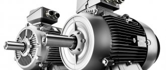
Let's look at the “heart” of milling, grinding, universal and many other machines. The focus is on the stepper motor: design and principle of operation, circuit diagram and applications, types of design and programming options. We will tell you all these and other important points so that you understand what it is and which model to choose in accordance with the specifics of the tasks being solved.
Let us immediately note that the subject of our interest today is used not only in complex equipment that solves critical problems, but also in relatively simple production mechanisms and even in household appliances. It is in demand in all cases where it is necessary to maintain sufficiently high-speed rotation of the shaft, while simultaneously combining it with precise positioning, and therefore will remain relevant for many years to come.
What is a stepper motor
According to the most popular definition, this is a machine that converts electrical energy (it receives it from the network) into mechanical energy by carrying out discrete (attention, not continuous, this is important) movements of the rotor. Moreover, after each such action, the position of the dynamic part is fixed.
All individual movements are of the same magnitude, and together they form a complete revolution (cycle). Therefore, by counting their number, you can easily and with high accuracy calculate the absolute position of the tool. Their total number, by the way, depends on a number of factors: the nature of the connection, the type of device, the method of specifying commands and other factors.
Operating principle of a stepper motor
- Voltage is applied to the terminals, due to which the special brushes begin to rotate.
- Under the influence of incoming pulses, the rotor is set to its initial position and then moves at the same angle.
- The microcontroller (in most cases, although other external control circuitry is possible) drives the gear magnets. The one to which energy is applied attracts the gear, thereby ensuring the rotation of the shaft.
- The remaining magnets are by default aligned with the leader, so they move along with it towards the next part.
- The gear rotates by switching electromagnets in order - from the main one to the next one and so on. At the same time, it is aligned with the previous wheel, which completes the cycle.
The step of the stepper motor is the algorithm described above, and it is repeated the number of times necessary to complete the technological operation.
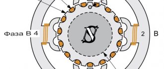
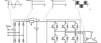
An idea of the appearance and nature of functioning will be complemented by the following figure:
It is clear from it that the stator includes four windings arranged crosswise, that is, at an angle of 90 0 to each other. From here it is clear that discrete movement will be carried out by the same amount of degrees. If the voltage is applied alternately - U1, U2, U3 and so on - the rotor will make a full revolution, and then go to the second circle, that is, it will begin to rotate - until it needs to be stopped. Well, to change the direction of its movement, it is enough to use the turns in the reverse order.
What are stepper motors: let's look at their varieties
The operating modes of the motor determine 2 characteristics: the step size and the force applied to move. You can vary them by changing the connection method, the structure of the windings or shaft.
Accordingly, the classification of drives is carried out according to the following parameters:
- Regarding the design of the rotor, its structure plays a key role, since the specifics of interaction with the electromagnetic field of the stator depend on it. There are 3 options, and we will consider each of them below, with all the features, pros and cons.
- By type (number of windings) - as their number increases, the rotation becomes smoother, but at the same time the cost of the power unit increases, although the torque remains unchanged. They can be uni- and bipolar, in the first case they are connected with a branch from the midpoint, in the second - through 4 outputs.
Now let's pay attention to the structure of the shaft.
Variable reluctance stepper drives
As the name suggests, it does not have its own source of a constant field; In addition, its rotor is made of soft magnetic material and has a toothed shape. Through the contact areas closest to the stator, closure occurs - with attraction to the poles, providing discrete movements. In its design, it is similar to a gear, in which the rotational force appears due to opposing pairs and alternating current flow.
The key advantage is that there is no stopping moment, because the field, which in other cases can influence the reinforcement, is simply absent. You get a synchronous power unit in which the rotor and stator turn simultaneously and in unison.
Having the same dimensions as other varieties, these models develop less torque. The movement is carried out by 5-15 degrees, and this is relatively rough and often inaccurate. This explains the somewhat limited scope of application of a reactive stepper motor: where a motor of this type is used, it is in specific machines, all the parts of which are manufactured by the manufacturer independently.
With permanent magnets
Again, it is immediately clear what their peculiarity is - the presence of their own source of a constant field, which is the basis of the moving element and contains 2 or more poles. It is the latter that ensure rotation of the rotor by applying voltage to the windings and attraction/repulsion.
The movement can be carried out either completely perpendicular to the previous position, or halfway; By increasing the number of magnetic pairs, you can adjust the length, and therefore the number of discrete movements, bringing their total number to 48 per full revolution. This allows you to very accurately install the working tool in the right place and is a competitive advantage of the power unit.
Hybrid
The design of this type of stepper motor was developed to combine the advantages of the previous two. It is a cylindrical field source, magnetized longitudinally, that is, a pair of poles with special surfaces - with applied teeth. The latter provide excellent retention without reducing torque.
Practical advantages:
- small step - 0.9-50 - which allows precision positioning due to a large number of discrete movements (up to 400 per cycle);
- high speed and smooth operation.
Yes, they are more expensive than the two previous types, since they are more difficult to manufacture, but this is a relative minus. Due to their advantages, these are the most common options today, used in the most critical cases: installed in CNC machines, in modern robotics devices, on medical and office equipment.
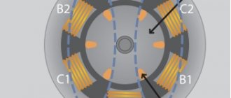
Active type synchronous stepper motors
Unlike synchronous machines of continuous rotation, stepper motors have pronounced poles on the stator, on which the coils of the control windings are located. Let us consider the operating principle of an active type stepper motor using the example of a two-phase motor.
There are two types of switching of the stepper motor winding: symmetrical and asymmetrical.
With a symmetrical switching system, the same number of control windings is excited on all four cycles.
With an asymmetric switching system, even and odd cycles correspond to a different number of excited control windings.
The rotor of an active type stepper motor is a permanent magnet, with more than 1 pair of poles, made in the form of an “asterisk”.
The number of clock cycles KT of the control system is called the number of states of the switch during its operating period T. As can be seen from the figures, for a symmetrical control system KT=4, and for an asymmetrical control system KT=8.
In general, the number of cycles KT depends on the number of control windings (stator phases) mу and can be calculated using the formula:
KT = mun1n2,
where: n1=1 - with a symmetrical switching system;
n1=2 - with an asymmetric switching system;
n2=1 - with unipolar switching;
n2=2 - with bipolar switching.
With unipolar commutation, the current in the control windings flows in one direction, and with bipolar commutation, it flows in both. The synchronizing (electromagnetic) torque of a machine is the result of the interaction of the rotor flux with the discretely rotating magnetic field of the stator. Under the influence of this moment, the rotor tends to occupy a position in the space of the machine in which the axes of the rotor and stator flows coincide. We considered stepper synchronous machines with one pair of poles (p=1). Real stepper micromotors are multi-pole (p>1). For example, let's take a two-pole three-phase stepper motor.
A motor with p pairs of poles has a toothed, star-shaped rotor with 2p permanent magnets evenly spaced along the circumference. For a multi-pole machine, the angular pitch of the rotor is equal to:
αsh=360/Ktr
The smaller the machine step, the more accurately (in absolute value) the angle will be worked out. The increase in the number of pole pairs is associated with technological capabilities and an increase in the leakage flux. Therefore p=4...6. Typically, the rotor pitch of active stepper motors is tens of degrees.
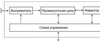
Stepper motor control principle
There are 3 main modes set by the driver, that is, the chip that sends the signals. Here they are:
- full-,
- semi-,
- and microstepping.
Each of them has its own characteristics. We have already described the first of them indirectly above, and it comes down to alternating phase switching; Moreover, only one of them at any moment can be connected to the source - they should not overlap each other. This law is reflected in the English name of the method – one phase – one step. The equilibrium points must coincide with the direction of the stator poles.
The downside here is that only half of the windings (for a bipolar unit) or even a quarter (for a unipolar unit) are used at the same time.
You can also choose the operating principle of the stepper motor, in which power will be supplied to all turns at once. It is known as the two-phase-on (full step) method, and with it the rotor remains in a state of equilibrium between the force lines of the stationary part of the shaft, and shifted by half of the discrete movement. Thanks to this solution, torque can be increased to 35-40%.
Half-step mode
Every second movement involves one phase, while there is a pair between them. This makes it possible to halve the angle and, therefore, double the number of transitions during a revolution. It is convenient precisely because it provides results relatively simply, which is why it is quite common.
With such a device and the operation of a stepper motor, it is important to remember that it must be stopped with the formation of a holding current - small, much less than the rated one, but still necessary and important. It is needed to automatically fix the rotor position after a complete power outage. Otherwise, the movable shaft will be in a free state and, under mechanical influence (which is very likely), will move, which cannot be allowed. But when it is supplied, there is no need to organize a braking system, add a mechanical lock or other element that can become a “weak link”, that is, reduce the overall reliability of the power unit.
Microstepping mode
Let's consider how a step-by-step motor operates in this case: the operating principle is reduced to the inclusion of two phases with an uneven distribution of winding current. Due to this, the magnetic field of the stator shifts, and after it the position of the rotor. The disproportion between switchings is characterized by small discreteness.
Due to this approach, extremely small steps are carried out - 1/3 of the full one or even shorter, up to 1000 per revolution. This allows you to maximize the accuracy of tool installation, although it significantly complicates the control system. In practice, this solution is in demand in particularly complex and critical cases, when creating and using relatively expensive but precision machines.
Control Modes
Now let's look at different ways to supply current to the windings and see how the motor shaft rotates as a result.
Wave control or full step control of one winding
This method is described above and is called wave control of one winding. This means that only one winding has electrical current flowing through it. This method is rarely used. Basically, it is used to reduce energy consumption. This method allows you to obtain less than half the motor torque, therefore, the motor load cannot be significant.
This motor will have 4 steps per revolution, which is the nominal number of steps.
Full step control mode
The second and most commonly used method is the full step method. To implement this method, voltage is applied to the windings in pairs. Depending on the method of connecting the windings (series or parallel), the motor will require double the voltage or double the current to operate relative to that required when exciting one winding. In this case, the motor will produce 100% of the rated torque.
Such a motor has 4 steps per full revolution, which is the nominal number of steps for it.
Half-step mode
This is a very interesting way to get double the accuracy of a positioning system without changing anything in the hardware! To implement this method, all pairs of windings can be energized simultaneously, causing the rotor to turn half its normal pitch. This method can also be implemented using one or two windings. Below is how it works.
Single winding mode
Double winding mode
Using this method, the same motor will be able to produce twice the number of steps per revolution, which means double the precision for the positioning system. For example, this motor will give 8 steps per revolution!
Microstepping mode
Microstepping mode is the most commonly used method of controlling stepper motors today. The idea of a microstep is to supply power to the motor windings not with pulses, but with a signal resembling a sine wave in its shape. This method of changing position from one step to the next allows for smoother movement, making stepper motors widely used in applications such as positioning systems in CNC machines. In addition, the jerks of various parts connected to the motor, as well as the shocks of the motor itself, are significantly reduced. In microstepping mode, the stepper motor can rotate as smoothly as conventional DC motors.
The shape of the current flowing through the winding is similar to a sine wave. Digital waveforms may also be used. Here are some examples:
The microstepping method is actually a method of powering the motor, not a method of controlling the windings. Therefore, microstepping can be used in both wave control and full-step control mode. The following demonstrates how this method works:
Although microstepping appears to make the steps larger, this actually does not happen. Trapezoidal gears are often used to improve accuracy. This method is used to ensure smooth movement.
Advantages and disadvantages
We have already looked at how a stepper motor works, where it is used, and what it is, but our description would be incomplete without an analysis of the pros and cons of its standard models.
The list of objective advantages:
- Maintains full torque as ground speed gradually decreases, even before stopping.
- Precise positioning within the selected mode, without any feedback; the number of discrete movements is specified by the angle of rotation.
- The position of the power unit is fixed immediately at the moment the movement stops - the holding current ensures the absence of inertial shifts.
- Quick start and reverse, quick switching.
- The rotation can be controlled precisely; again, no return influence is observed.
- The high level of overall reliability is partly due to the fact that there are no commutator brushes or other elements that could become a “weak link”.
Practical disadvantages include:
- The operating principle of a stepper motor can be accompanied by overly complex controls.
- The speed is not very high nominally.
- Sometimes resonance occurs, which can lead to failures in the installation of instruments.
- The power density is relatively small.
- Due to mechanical overload, positioning may be lost.
Obviously, the pros are greater than the cons, and besides, there are areas in which the power units in question simply cannot be avoided, when they are many times superior to manifold units. These are those cases of precision mechanics in which you need to move nodes with instant stops and rapid changes in the motion vector.
Important Features
- From the point of view of electrical engineering, a step drive is a rather complex device with a number of parameters. Here are the main ones:
- The number of complete steps during one cycle - accuracy, smoothness, and resolution depend on it; modern models should be at the level of 200-400.
- Angle of discrete movement (shaft rotation) – calculated as 360 0/number of individual movements per revolution; a similar indicator to the previous one, simply presented in a different form; its current values are 1.8-0.9 degrees.
- Breakdown voltage - the maximum at which the insulation is broken, determines the safety of use.
- Permissible constant voltage - measured in static mode on turns; in some cases it is not given, but even then it can be calculated using Ohm’s law.
- The rated current is the highest possible for the safe and uninterrupted operation of the power unit.
- Winding resistance - this, together with the previous characteristic, indicates how many volts can be supplied to step-by-step electric motors.
- Phase inductance – determines the rate of current rise; becomes especially important when the shaft rotates rapidly.
- Insulation resistance is between the windings and the housing.
A separate family of parameters are the moments:
- torque – depends on the rotation speed; the maximum for a given power unit is indicated;
- inertia - the smaller it is, the faster the acceleration;
- locking – needed to rotate the shaft in the event of a lack of power;
- holding – active when completely stopped and two phases are supplied with rated current.
Connection
The selected device and operating diagram of the stepper motor depend on the following factors:
- total number of wires;
- launch character.
There are models with 4, 5, 6, 8 connectors; “Quad” is only suitable for bipolar ones, since they have a pair of phase windings with two connectors and continuous connections need to be established. The “Six” also has center taps on each turn and is therefore universally applicable to all power units.
Typical switching options look like this:
For trouble-free operation, it is important to remember the rules for applying the rated voltage, as well as changing the torque speed and reducing the linear one.
Buyer's Guide: What to Consider Before Choosing a Stepper Driver for Your CNC
- Select your stepper motor first: Don't select a stepper driver until you have decided which stepper motors you will use.
- Stepper Motors Peak Current: This is the main value that determines your driver. Ideally, you should purchase a stepper driver with a maximum current rating that is 1.4 times that of a stepper motor. If this is not an option, make sure your driver's current is at least the same as the motor's to get maximum torque.
- Power Supply: Get a reliable power supply with a voltage rating that matches your stepper driver for maximum performance. To obtain high torques at high speeds, the voltage must be increased significantly.
- Number of Drivers: The number of stepper drivers needed is the same as the number of stepper motors you plan to use.
- Resonance and noise: As current increases, unreliable stepper drivers lead to noise and vibration. This is why anti-resonance is so important.
Types of control
In addition to the modes already discussed - full-, half- and micro-, there are others that determine how signals are supplied to the poles and, accordingly, how the stepper motor works. Let's consider two fundamentally different types of them.
Without controller
It is implemented thanks to the H-bridge (often called exactly that), which allows you to almost instantly switch the polarity and provide fast reverse. The system is built on transistors and/or microcircuits: the selected ERE guarantee the logical chain along which the keys move. Suitable for brushless models.
According to this diagram, voltage goes from the power source to the bridge. The contacts are switched on in pairs (S1-S4 and S3-S2), due to which current passes through the windings, starting rotation in the desired direction.
With controller
Let's take a closer look at it, because it determines how a stepper motor works and what it is: it is an electronic unit that generates a sequence of signals and sends them to the stator coils. To prevent it from malfunctioning in the event of an emergency (for example, during a short circuit), the drive terminals are equipped with diodes that do not allow reverse pulses to pass through. Makes it possible to implement a variety of modes.
Popular control schemes
We bring to your attention two interesting options:
The key advantage here is noise immunity. Both the direct and inverse signals are connected to their respective poles directly. When implementing it, it is necessary to take care of shielding the signal connector. Suitable when you plan to use a stepper motor with low power: the operating principles will be followed even under high loads.
Another decent solution:
The key feature is the combination of inputs connected to the positive pole. If at the same time a power supply exceeding 9 V is supplied, it will be necessary to supplement the circuit with a current limiting resistor. In general, it is very convenient in that it provides the ability to strictly and accurately set the speed and number of movements during a revolution.
If a logical 1 is applied to one of its D-pins and the others are left at 0, the transistor will open, which will ensure the passage of the signal to the coil. This is a simple way to carry out discrete movement.
We advise you to see in practice what a stepper motor is, the purpose of the device and the principle of operation - try to give it some commands yourself. Taking the latest development as a basis, it is not a problem to make a printed circuit board, to order or even on your own, by soldering the necessary electronic components into it (almost all diodes, transistors, resistors can be removed from used equipment). Control can be carried out from a regular computer.
EQUIPMENT TECHNOLOGY DEVELOPMENT
As a rule, the logical signals for controlling the stepper motor are generated by a microcontroller. The resources of modern microcontrollers are quite enough for this even in the most “heavy” mode – microstepping.
To connect stepper motors via low-current logic signals of microcontrollers, signal amplifiers - drivers are needed.
Driver features include:
- ensuring the required current and voltage on the phase windings of the motor;
- winding switching; inclusion;
- shutdown;
- polarity change;
This article is about simple drivers that are sufficient for most applications. There are drivers with much greater capabilities:
- ensuring a rapid increase in current when turned on and a rapid decrease when turned off;
- reducing the current to fix the position of a stopped engine;
- protective functions;
- generation of winding current and voltage for microstepping mode;
- and many others.
The circuitry of such drivers is quite complex, and these functions are not necessary in most applications.
According to the connection diagram, stepper motors are divided into unipolar and bipolar. The drivers for these two engine options are fundamentally different.
- Unipolar stepper motor driver.
- Unipolar stepper motor driver circuit.
- Bipolar stepper motor driver.
- Bipolar stepper motor driver circuit.
- L298N bipolar stepper motor driver.
- Characteristics of the L298N chip in Russian.
- L298N driver connection diagram.
Unipolar stepper motor driver.
Motors with the following winding configurations can operate in unipolar mode.
Let me remind you of the principle of controlling a unipolar stepper motor. Four windings with a common wire connected to one pole of the power source. If the other terminals of the windings are connected in series to the other pole of the source, the motor rotor will rotate.
To switch the windings in this way, only four keys are enough to connect the windings to ground. The switching diagrams for the windings of the two previous engine options look like this.
If you close keys 1, 2, 3, 4 in sequence, the engine rotor will rotate.
Unipolar stepper motor driver circuit.
In practice, switches can be made using bipolar transistors, but it is preferable to use low-threshold MOSFET transistors. I use IRF7341 transistors. These are MOSFET transistors with the following parameters:
- maximum permissible current 4 A;
- maximum voltage 55 V;
- open resistance 0.05 Ohm;
- switching threshold 1 V;
- made in a miniature SO-8 case;
- There are two transistors in the housing.
An extremely convenient option for use in a unipolar stepper motor driver.
- There is no need for key cooling radiators;
- very low voltage drop across an open transistor;
- small sizes;
- only two 8-pin packages for a two-phase stepper motor driver.
It is impossible to create switches with such parameters on bipolar transistors. There are many other options for MOSFET transistors for switches, for example IRF7313 (6 A, 30 V, 0.029 Ohm).
The switch circuit on a MOSFET transistor for one phase looks like this.
The key is controlled directly from the microcontroller by logical levels KMOP or TTL (0 / +5 V). When the control signal is high (+5 V), the switch is open and current flows through the phase winding. The diode bypasses the motor winding in the opposite direction. It is necessary to protect the transistor from self-induction voltage surges when a phase is turned off. To control motors at significant rotation speeds, it is better to use high-frequency diodes, for example, FR207.
Here is a fragment of a diagram for connecting a unipolar stepper motor to a microcontroller.
There is no protection against short circuits in this circuit. Implementing protection significantly complicates the driver. And short circuits in the windings of stepper motors practically never happen. I have not encountered such a phenomenon. And against the backdrop of troubles about a burnt-out expensive engine, replacing the transistor does not look like a problem.
By the way, mechanical jamming of the stepper motor shaft does not cause unacceptable currents in the driver keys and does not require protection.
And this is an image of a controller board for a unipolar stepper motor with a PIC controller from Microchip.
A simple board with an eight-bit PIC18F2520 microcontroller controls:
- two stepper motors with phase current up to 3 A;
- two PWM keys for electromagnets;
- reads the status of 4 sensors;
- exchanges data over the network with the central controller.
This controller is used as part of the stepper motor control system in almost all ROST packaging equipment.
Despite the simplicity of the controller, the following control modes are implemented:
- full-step, one phase per full step;
- full-step, two phases per full step;
- half-step;
- fixing the engine position when stopping.
The advantages of controlling a stepper motor in unipolar mode include:
- simple, cheap, reliable driver.
Disadvantages:
- in unipolar mode the torque is approximately 40% less compared to bipolar mode.
An example of a practical circuit for a simple unipolar stepper motor controller.
An article about connecting a unipolar stepper motor to an Arduino board.
Bipolar stepper motor driver.
Motors with any winding configuration can operate in bipolar mode.
A bipolar motor has one winding for each phase. Usually there are two windings AB and CD. In the first two options, four windings are connected so that two windings are obtained. The windings are connected in turn to the power source in one polarity, then in the other.
The bipolar motor driver must provide complex switching. Each winding:
- connected in direct polarity to the voltage source;
- disconnected from the voltage source;
- connected with opposite polarity.
The switching diagram of one winding of a bipolar motor looks like this.
To provide two polar switchings from one power source, 4 switches are required. When switches 1 and 2 are closed, the winding is connected to the power source in straight polarity. Closing switches 3 and 4 supplies the winding with reverse voltage polarity.
The complexity of the bipolar stepper motor driver is caused not only by the large number of switches (4 keys per winding, 8 keys per motor), but also:
- complex control of the upper keys (1 and 4) from logical signals “tied” to ground;
- problems with through currents when simultaneously opening the keys of one arm (1.3 or 2.4).
Through currents can arise due to different speeds of the lower and upper switches. For example, the lower key has already opened, but the upper key has not had time to close.
Bipolar stepper motor driver circuit.
It is quite difficult to implement a bipolar stepper motor driver circuit using discrete elements. I can show you my circuit that connects a bipolar motor to a unipolar driver. This circuit is used to control bipolar motors from the controller given as an example in the previous chapter.
The scheme is quite simple. The problem of through currents is solved by using 0.22 Ohm resistors in switched circuits. At the moment of commutation of MOSFET transistors, the upper and lower switches are simultaneously open for a short time. These resistors limit the through current. Unfortunately, they also limit the operating current of the motor. Therefore, despite the powerful transistors, a driver according to this circuit can be used for switching currents of no more than 2 A. The circuit does not require diodes to protect against the self-induction emf of the windings, because these diodes are integrated into MOSFET transistors.
It is much more convenient and practical to use integrated bipolar stepper motor drivers. The most common of them is the L298N chip.
L298N bipolar stepper motor driver.
There is practically no description of this microcircuit in Russian. Therefore, I present the parameters of the L298N in sufficient detail, according to the official materials of the manufacturer of this chip - STMicroelectronics (datasheet l298n.pdf).
The L298N is a full bridge driver for driving bidirectional loads up to 2A and 46V.
- The driver is designed to control components with inductive loads such as electromagnets, relays, stepper motors.
- Control signals are TTL compatible levels.
- Two enable inputs make it possible to turn off the load regardless of the input signals of the microcircuit.
- It is possible to connect external current sensors to protect and control the current of each bridge.
- The logic power supply and the L298N load are separated. This allows the load to be supplied with a voltage of a different value than the power supply to the microcircuit.
- The microcircuit has overheating protection at + 70 °C.
The block diagram of the L298N looks like this.
The microcircuit is made in a 15-pin package with the ability to attach a cooling radiator.
L298N pin assignments.
| 1 | Sense A | Resistors are connected between these terminals and the ground - current sensors to monitor the load current. If current control is not used, they are connected to ground. |
| 15 | Sense B | |
| 2 | Out 1 | Bridge A outputs. |
| 3 | Out 2 | |
| 4 | Vs | Load power supply. A low-impedance capacitor of at least 100 nF must be connected between this pin and ground. |
| 5 | In 1 | Bridge control inputs A. TTL compatible levels. |
| 7 | In 2 | |
| 6 | En A | Bridge operation permission inputs. TTL compatible levels. Low signal level prohibits bridge operation. |
| 11 | En B | |
| 8 | GND | General conclusion. |
| 9 | Vss | Power supply for the logical part of the microcircuit (+ 5 V). A low-impedance capacitor of at least 100 nF must be connected between this pin and ground. |
| 10 | In 3 | Bridge control inputs B. TTL compatible levels. |
| 12 | In 4 | |
| 13 | Out 3 | Bridge B outputs. |
| 14 | Out 4 |
Maximum permissible parameters L298N.
| Designation | Parameter | Meaning |
| Vs | Supply voltage | 50 V |
| Vss | Logic supply voltage | 7 V |
| Vi,Ven | Logic input voltage | -0.3…7 V |
| Io | Output current (per channel)
| 3 A 2.5 A 2 A |
| Vsens | Voltage current sensors | -1…2.3 V |
| Ptot | Power dissipation (case temperature 75°C) | 25 W |
| Top | Operating temperature of the crystal | -25…130 °C |
| Tstg | Storage temperature | -40…150 °C |
Parameters for calculating thermal conditions.
| Designation | Parameter | Meaning |
| Tth j-case | Thermal resistance crystal-case | 3 ºC/W |
| Tth j-amb | Thermal resistance crystal-environment | 35 ºC/W |
Electrical characteristics of the L298N driver.
| Designation | Parameter | Meaning |
| Vs | Supply voltage (pin 4) | Vih+2.5 …46 V |
| Vss | Logic power | 4.5…5…7 V |
| Is | Quiescent current consumption (pin 4)
| 13 … 22 mA 50 … 70 mA 4 mA |
| Iss | Quiescent current consumption (pin 9)
| 24 … 36 mA 7 … 12 mA 6 mA |
| Vil | Input voltage low (pins 5, 7, 10, 12, 6, 11) | -0.3…1.5 V |
| Vih | High level input voltage (pins 5, 7, 10, 12, 6, 11) | 2.3…Vss V |
| Iil | Low level input current (pins 5, 7, 10, 12, 6, 11) | -10 µA |
| IIh | High level input current (pins 5, 7, 10, 12, 6, 11) | 30 … 100 µA |
| Vce sat(h) | Upper switch saturation voltage
| 0.95…1.35…1.7 V 2…2.7 V |
| Vce sat(l) | Lower key saturation voltage
| 0.85…1.2…1.6 V 1.7…2.3 V |
| Vce sat | Total voltage drop across public switches
| 1.8 ... 3.2 V 1.8 ... 4.9 V |
| Vsens | Current sensor voltage (pins 1, 15) | -1…2 V |
| Fc | Switching frequency | 25 … 40 kHz |
Connection diagram of a stepper motor to a microcontroller using the L298N driver.
The operation diagram of this circuit in full-step mode looks like this.
If enabling inputs and current sensors are not used, the circuit looks like this.
And here is a fragment of the bipolar stepper motor controller circuit.
In terms of functions, this is an analogue of the controller described in the chapter on unipolar motors, only for bipolar ones. It is also assembled on a Microchip PIC controller and controls two bipolar stepper motors with a phase current of up to 2 A. The functionality and motor control modes are the same.
The advantages of controlling a stepper motor in bipolar mode include:
- the torque is approximately 40% greater compared to unipolar mode.
- You can connect stepper motors with any winding configuration.
Disadvantages:
- complex driver.
Another stepper motor controller circuit.
Support the project
0
Author of the publication
offline for 5 days
Edward
236
Comments: 1789Publications: 183Registration: 13-12-2015