The push-button station is designed for switching circuits designed to control alternating current, the voltage of which is up to 660 V with a frequency of 50 and 60 Hz. In addition, they can be used in DC circuits with voltages up to 440 V or for supplying control signals. The latter can be performed either remotely or on site.
Typically, such products are needed to control devices of various types at a distance.
The design of the control panel is quite simple , there are a minimal number of parts in it, but there is one very important function - to issue commands and check how completely they have been executed.
They are used in automatic systems, in particular, such devices can be placed in metal and woodworking machines, various types of mechanisms aimed at lifting and moving loads.
Its body is usually made of plastic, there are at least 2 control elements, but there can be much more.
Its pusher is mushroom-shaped or made in the shape of a cylinder. Cylindrical products are available in black, white, yellow, red, blue or green. The mushroom-shaped pusher is painted red or black.
The contact elements operate via both the making and breaking principles.
Explosion-proof models are used to remotely control electric drives of stationary or mobile installations. These devices can be used in the gas and oil industries, as well as in other types of industrial production.
magnetic switch
This system is quite flexible and is equipped with several modules, as well as a magnetic starter. The latter is connected directly through a push-button post, due to which the reliability of its operation becomes very high.
This starter is a switching structure, due to which electricity is disconnected or connected.
Such starters have a metal or plastic body and can be used in direct or alternating current networks. They are often used in automated systems and devices; in addition, they are designed to turn systems on or off in the event of an emergency.
They can be remote or built directly into the design of the product.
Device and design
The standard push-button control station has the following design features:
- Each of the buttons does not have a fixed position.
- The “Start” button is usually painted green, and sometimes even backlit when turned on; it also has normally wired contacts; it itself is used to activate the operation of a particular mechanism.
- The “Stop” button is usually red and is located on closed contacts. Due to this, the supplied voltage is removed from the device and its operation is suspended.
- In addition , push-button control stations can have a metal or plastic body. Each of them has its own level of protection. They are allowed to be used in devices intended for distribution purposes, as well as in the automation of most industrial systems.
- The push-button station is the basis of the design of most remote controls; it is directly involved in turning the equipment on or off, and acts in an emergency.
If the equipment is dangerous to human life or health, similar devices are produced with an increased degree of protection. The connection diagram in this case is much more reliable, and the remote control itself can be connected to various devices.
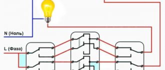
Often, the installation is controlled from 2 points. As a rule, this is caused by a certain production need. Typically, various electric motors operate using this technology, but other equipment can also operate.
Magnetic starter control circuit from two and three places
Hello, dear readers and guests of the Electrician's Notes website.
After publishing an article about a magnetic starter connection diagram, I very often began to receive questions about how to control a motor from two or three places.
And it’s not surprising, because such a need can arise quite often, for example, when controlling an engine from two different rooms or in one large room, but from opposite sides or at different height levels, etc.
So I decided to write a separate article about this, so that those who come back with a similar question will not have to explain every time what needs to be connected where, but simply give a link to this article, where everything is explained in detail.
So, we have a three-phase electric motor controlled through a contactor using one push-button post. I explained in great detail how to assemble such a circuit in an article about the magnetic starter connection diagram - follow the link and get acquainted.
Here is a diagram for connecting a magnetic starter through one push-button post for the example above:
Here is a mounting version of this circuit.
Be careful! If your linear (phase-to-phase) voltage of a three-phase circuit is not 220 (V), as in my example, but 380 (V), then the circuit will look similar, only the starter coil must be at 380 (V), otherwise it will burn out.
Also, control circuits can be connected not from two phases, but from one, i.e. use any one phase and zero. In this case, the contactor coil should be rated 220 (V).
Engine control scheme from two places
I slightly modified the previous diagram by installing separate circuit breakers for the power and control circuits.
For my example with a low-power engine, this was not a critical mistake, but if you have an engine of much higher power, then this option will not be rational and in some cases not even feasible, because the cross-section of the wires for the control circuits in this case should be equal to the cross-section of the wires of the power circuits.
Let's assume that the power and control circuits are connected to one circuit breaker with a rated current of 32 (A). In this case, they must be of the same cross-section, i.e. not less than 6 sq. mm for copper. What is the point of using such a cross-section for control circuits?! The consumption currents there are quite negligible (coil, signal lamps, etc.).
What if the engine is protected by a circuit breaker with a rated current of 100 (A)? Imagine then what wire cross-sections will need to be used for control circuits. Yes, they simply simply will not fit under the terminals of coils, buttons, lamps and other low-voltage automation devices.
Therefore, it would be much more correct to install a separate machine for control circuits, for example, 10 (A) and use wires with a cross-section of at least 1.5 sq. mm for the installation of control circuits.
Now we need to add another push-button control station to this circuit. I’ll take as an example a PKE 212-2U3 post with two buttons.
Operating principle
Such a device is a switching device, thanks to which the electric current is controlled and distributed along the circuits to which it is connected.
On the one hand, at the push-button station there are power contacts, which perform switching on, switching, normal and emergency shutdown of the equipment.
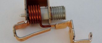
On the other hand, an electromagnetic coil is installed, due to which these contacts are switched on and off:
- In the first part, these power contacts, as a rule, are movable and are located on a dielectric traverse. If these elements do not have such a characteristic as mobility, then they are placed directly on the body, which must also be dielectric. With their help, power lines are connected. In a calm state, such contacts are open, and no electric current flows through them. There is no load on them in this state. They are held in this state thanks to a special spring;
- The second part is equipped with an electromagnetic coil. Until a sufficient amount of voltage is applied to it, it is also at rest. When the voltage increases, an electromagnetic field appears on the coil circuit, creating an electromotive force. Due to it, a movable core or armature with power contacts attached to it approaches the coil. As a result, the circuits connected through them are closed and a workload is formed.
- When the voltage is removed from the coil , the electromotive force disappears, and the armature cannot be held in the active position; under the action of the spring, it has to return to its original position. As a result of this, the power contact circuits open and the installation stops working.
Connection diagram for a 220 V magnetic starter
Here, the current is supplied to the magnetic coil KM 1 through a thermal relay and terminals connected in a chain of buttons SB2 for turning on - “start” and SB1 for stopping - “stop”. When we press “start”, electric current flows to the coil. At the same time, the starter core attracts the armature, resulting in the closure of the moving power contacts, after which voltage is supplied to the load. When “start” is released, the circuit does not open, since the KM1 block contact with closed magnetic contacts is connected parallel to this button. Thanks to this, phase voltage L3 is supplied to the coil. When you press “stop,” the power is turned off, the moving contacts return to their original position, which leads to de-energization of the load. The same processes occur when the thermal relay P operates - a break in the zero N supplying the coil is ensured.
Advantages
The main positive aspects of its operation are:
- The configuration of the device can be standard or tailored to the specific requirements of the direct customer.
- The body is made of non-flammable materials - special refractory fire-resistant plastic or metal.
- Between the cover and the body there is a small gasket made of rubber, which creates a good seal.
- The push-button post implies the possibility of installing 2 light indicators - one for each control button.
- The structure's seal is well protected from the negative effects of environmental factors.
- on the side of the structure through which the cable is inserted.
- All fasteners are made of stainless steel - grade 316 steel, which makes the fastenings of this device quite reliable.
Largely due to all these advantages, push-button posts have one of the highest degrees of protection.
Main types:
Typically used when working with woodworking devices for both industrial and domestic purposes.
Used in industry where there is no threat of explosion, and the total concentration of dust or gas will not lead to failure of such equipment.
Used when working with electrical equipment installed on mechanisms capable of lifting large loads, for example, beam cranes, overhead cranes, and so on. With the help of such a device, the tool will be controlled from the surface of the earth in manual mode.
How to change the direction of rotation of a motor using a starter
Three-phase electric motors make it possible to set the direction of rotation. There are many schemes for single-phase 220 V power supply. And for three-phase (380 V) switching, there is a connection diagram for a reversible magnetic starter.
The device consists of two independent circuits, with separate control of each group of contacts (pm1 and pm2). Each solenoid winding (PM1 and PM2) is controlled by its own button. In this case, there is only one stop key; it simply breaks the control circuit (as in a single starter). The connection of the input and output contacts of the second group is made with the so-called “phase shift”. In this case, the windings of the electric motor create torque on the shaft in the opposite direction.
The thermal relay is unchanged: their task is to open the starter in case of overload.
There is one feature:
To prevent a short circuit between phases, groups of contacts (pm1 and pm2) should not be closed at the same time. Therefore, they are mechanically placed on one rod, and purely physically cannot be connected to the power bus together. If you try to press the second button (while the first one is working), the power supply to the consumer will turn off.
Technical characteristics and operating conditions
Despite the huge variety of models available for sale, their technical characteristics are the same, but may differ slightly in parameters:
- Rated voltage (in the case of alternating current – up to 660V, with direct current – up to 440V).
- Lowest operating voltage (with alternating current - from 36, with direct current - from 24).
- Rated voltage across the insulating layers (up to 660V).
- Rated current (10A).
- Through current flowing through the push-button post for one second (200A).
- Nominal operating mode (there can be 4 types: short-term, intermittent, long-term and intermittent-long).
Operation largely depends on the type of control station, but there are a number of general points:
- First of all , the push-button post should not be located above 4300 m above sea level.
- The temperature in a workshop or other work area can be from -40 to +40 degrees.
- If the humidity regime exceeds 80% at a temperature of 20 degrees, then this will soon lead to damage to the contacts; at a temperature of 40 degrees, this figure should not exceed 50%.
- There are devices capable of operating in explosive environments, but most models are not designed for this.
- In addition , the environment should not contain large amounts of dust capable of conducting electric current, corrosive gas and water vapor.
- to expose the structure to direct sunlight.
Open starters
An open type starter (manual) can be connected via a regular trigger. Controllers are most often used with four connectors. The output contacts are connected to the post via zero phase, and the resistance should be about 45 Ohms. Wired type controllers are connected to the converter. To check the phase, a tester is used. Starters with a dinistor are installed through an electrode adapter. Quite often rectifiers are used with low conductivity. The closing contacts must be connected on the top panel. To avoid problems with failures, it is important to check the insulation and take care of the rectifier.
Model overview
Push-button station PKE 222-3-U2-IP54-KEAZ
It has 3 buttons, is placed in refractory plastic, meets all state standards GOST 15150-69 and GOST 15543.1-89.
Its price is 237 rubles.
Push-button station Electrician PKU 15-21
It has 2 buttons, an LED activity indicator, is housed in an aluminum case, and has all the necessary certificates of conformity.
Costs 1248 rubles.
Hanging push button station Schneider Electric Harmony XAC-B XACB6913
The starter is designed for starting, installing and reversing three-phase asynchronous electric motors with a squirrel-cage rotor, as well as protecting them from overcurrents of unacceptable duration.
As an element of automatic control systems, electromagnetic starters are subject to high wear resistance requirements. Wear resistance classes: A, B and C. Starters are produced in versions with varying degrees of protection from touches and external influences (IP00, IP20, IP40, IP54). Climatic modification and placement categories according to GOST 15150-69 and GOST 15543.1-89.
Installation is carried out on a vertical surface using mounting screws, with an inclination of no more than 15 degrees. The altitude above sea level is no more than 2000 meters (when placed at an altitude of 2000 meters to 4300 meters, the rated current of the starter is reduced by 10%).
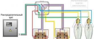
Connection
In most cases, a push-button station is used to switch the power supply to magnetic starters that are installed in the control circuits of asynchronous AC motors.
and controlling it using a three-button post is shown in the figure above, where the following notations are adopted:
- “Start forward/backward” and “Stop” are buttons on the control panel.
- KM1 and KM2 are coils of magnetic starters that perform direct and reverse activation of the electric motor.
- KM1.1…KM2.3 contacts of magnetic starters.
The scheme works as follows:
- When you press the push button “Start-forward” , power is supplied to the coil of the first magnetic starter (“KM1”); the group of normally open contacts KM1.1 closes, supplying power to the motor windings.
- Normally closed contacts “KM1.2” disconnect the pusher contacts “Start-backward”, blocking the activation of the coil of the magnetic starter “KM2”, and normally open contacts “” close parallel to the “Start-forward” button.
- When you press the “Stop” pusher, power is not supplied to the coils of both magnetic starters (“KM1”; “KM2”), they are turned off, the contacts “KM1.1” and “KM1.3” open, de-energizing the electric motor.
- When you press the “Start-Reverse” button, the contact closure procedures are similar, only they are carried out in relation to the second magnetic starter “KM2”.
Magnetic starter: purpose, device, connection diagrams
It is better to supply power to electric motors through magnetic starters (also called contactors). Firstly, they provide protection against inrush currents. Secondly, the normal connection diagram for a magnetic starter contains controls (buttons) and protection (thermal relays, self-retaining circuits, electrical interlocks, etc.). Using these devices, you can start the engine in the opposite direction (reverse) by pressing the corresponding button. All this is organized using diagrams, and they are not very complicated and can be assembled independently.
Design features
Depending on the number of controlled electricity consumers, the posts can be two-button ("Start" and "Stop" pushers) and multi-button. In addition, when performing electrical and electrical work, single buttons are used, which the user can independently install on any control panel.
Push-button stations are mounted in a plastic or metal case that has mounting holes for installing the fittings in a place convenient for use. A separate group consists of push-button stations designed to control hoists (PKT series), beam cranes and overhead cranes with ground control.
The main functional element of the device that starts, stops or switches the modes of the electricity consumer is a push button - an electrical switching fixture with manual control.
Today, control panels use two types of pushers:
- With self-return , in which the button returns to its original state due to a return spring installed on the pusher on the bottom side.
- Pushers with position fixation (self-holding), which close the contact and hold it until pressed again.
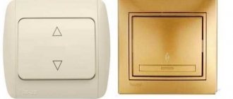
The most common is a two-button starting valve, the design of which is shown in Fig. 2. The remote control consists of a housing 1 and a front panel 2, which are connected to each other by screws 3. The buttons are painted in different colors and control a pair of contacts located inside the housing.
Instructions for PML-1100 series starters
The PML-1100 starter circuit has three adapters. The output contacts must be closed in the zero phase. The post is checked using a tester. Experts say that you should not use analog converters that have a low resistance level. If we consider simple switches, then the trigger is set to channel reception. The current relay is connected to the converter and closes in the first phase. If you have problems with overheating, you can try to reduce the load using a comparator.
Types of push-button control panels
Today, on the electrical equipment market, a fairly large number of different push-button remote controls are produced that control electrical equipment.
However, functionally and structurally, they are all identical and differ in design and brand. All model lines of this type of electrical fittings can be supplied in various placement categories and different designs.
Typically, these two parameters are reflected in the symbol of a specific model. Russian enterprises produce the PKE, PKT and PKT series for installation in industrial equipment control systems.
The PKE series has found the widest distribution in control circuits of wood and metalworking machines and industrial complexes.
The permissible operating parameters of these devices are as follows:
- Maximum value of switching voltage: constant – 400.0 volts; alternating (frequency 50.0 or 60.0 hertz) – 660 volts;
- Switching current – 10.0 amperes;
- Maximum number of actuation cycles – 5×10 6 .
The symbol for push-button stations of the PKE series is shown in Figure 3, in which the following characteristics are indicated by numbers:
- 1 – serial number designation;
- 2 – characteristics of the installation method (built-in or overhead);
- 3 – degree of protection category;
- 4 – body and panel material (metal or plastic);
- 5 – number of controlled contacts (the figure shows the designation for two contacts);
- 6 – a parameter indicating product modernization;
- 7 – category of accommodation and the corresponding climatic modification.
Rice. 4. Designation of the “PKU” series
Posts of the PKU series are intended for operation in an explosion-proof environment where the concentration of dust or gas will not impair their functionality.
The fittings have operational parameters similar to the PKE model line, however, the manufacturer has provided its own designation for this electrical fittings, which is shown in Figure 4.
The digital designations shown in the figure correspond to the following parameters, which allow you to characterize a specific device model:
- 1 – serial number designation;
- 2 – serial modification number;
- 3 – rated current switched by contacts of a separate button;
- 4 – the number of pushers installed in horizontal rows;
- 5 – the number of pushers installed in vertical rows;
- 6 – installation method (overhead, built-in or suspended);
- 7 – degree of electrical protection;
- 8 – category of accommodation and the corresponding climatic modification;
Fig.5 – PKT remote control
The PKT series is designed to work with electrical equipment of lifting mechanisms (electric hoists, overhead cranes and overhead cranes) with ground-based, manual control.
Operational and electrical parameters are similar to devices of the “PKE” and “PKU” series. Under the abbreviation “IEK”, Chinese fittings are sold on the Russian market of electrical products, whose characteristics are completely similar to Russian control posts.
The general view of this electrical fittings is shown in Figure 5.
In the designation “PKT-X1 X2 X3” the digital indices characterize the following parameters:
- X1 – series number;
- X2 – number of control buttons;
- X3 – placement category and corresponding climatic modification.
Explosion-proof starting fittings
Russian explosion-proof valves have in their letter designation an additional index “B” - “PVK”, or “KPVT”. They are most widespread in control circuits for electrical equipment operating in explosive environments in coal mines, oil storage facilities, paint shops and other similar facilities.
Hoist push-button controls “HAS-A” (“Schneider Electric” - Germany) and “KS” (“SN Promet” - Poland) are widely used. In addition, remote push-button control valves are becoming increasingly common in this category.
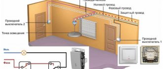
Connection diagram of a push-button post and its operating principle
To connect a contactor or starter to control the light from two buttons (like any other system), we need:
- Push button post.
- A contactor or starter with the number of power contacts (poles) equal to the number of phases.
- Three strands of wire.
Connecting the contactor to the push-button post is done as follows:
- The voltage of the device coil is determined (usually 220 or 380).
- The phase is taken from the power contacts (if the coil is 380, we take two opposite phases, if 220, we take phase and zero).
- Connect the phase wire to the normally closed contacts of the “STOP” button.
- The “START” button is connected in series with the “STOP” button.
- From a normally open pair of block contacts of a contactor or starter, lay two wires to the push-button post (from two contacts, respectively) and connect them to the “START”, so that its normally open pair and open block contacts are connected in parallel. In this case, the contacts to which the phase has now arrived will be conventionally called “1”, and to which the phase will be supplied after pressing the key and the block contacts are triggered “2”. Important note: by this step we already have an incoming phase through the normally closed “STOP” to the open “START”; the block contacts of the starter or contactor are also connected to the same circuit.
- We connect the coil output to block contact “2” (often on modern contactors they are designated as A1 and A2).
- We connect the second terminal of the coil to zero if it is designed for a voltage of 220V or to another phase - if for 380V, respectively.
- We connect the power supply wires; the phase to the push-button station is usually taken from these same terminals.
- Connect the wires from the lighting system (the lighting installations themselves).
Everything that is described above, but in graphical form, you can see in this diagram.
In the figure there is an additional power-on indication - a light bulb in the chain of control buttons and block contacts. It will allow you to understand whether the contactor and external light are turned on, without leaving the push-button post.
Note : the light control scheme using starters is also good because you can easily organize light control from two or more places - you just need to add push-button stations in parallel to the existing ones.
Cost indicators
The cost of Russian push-button posts is quite low and depends primarily on the number of buttons , category of placement and climatic design. Devices in a metal case are slightly more expensive than analogues installed in a plastic case.
For example, the price of two-button devices “PKE-222-2” is in the range of 250.0...280.0 rubles. A similar device with a mushroom-shaped “Stop” button will cost a little more – 380.0 rubles.
The price of one-button posts does not exceed 150 rubles. The six-button telpher remote control “PKT-60” costs 300.0 rubles. A device with a similar number of buttons and electrical parameters, equipped with a key (“foolproof”), will cost 200.0 rubles more.
>
Installation Tips and Tricks
- Before assembling the circuit, you need to free the working area from the current and check that there is no voltage with a tester.
- Set the core voltage designation which is mentioned on it and not on the starter. It can be 220 or 380 volts. If it is 220 V, phase and zero go to the coil. Voltage marked 380 means different phases. This is an important aspect, because if connected incorrectly, the core may burn out or will not fully start the necessary contactors.
- Starter button (red) You need to take one red “Stop” button with closed contacts and one black or green button with the inscription “Start” with invariably open contacts.
- Please note that power contactors only force or stop the phases, and the zeros that come and go, conductors with grounding are always combined at the terminal block, bypassing the starter. To connect a 220 Volt core to the addition, 0 is taken from the terminal block into the design of the starter organization.
You will also need a useful device - an electrician's tester, which you can easily make yourself.