If you have become the owner of an LED strip, power supply and all installation accessories and you are faced with the question of How to connect LED strip? then I ask you to pay attention to this article. In it we will answer the main questions that arise when installing and connecting diode strips.
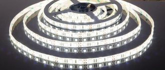
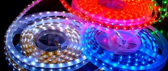
LED strips are known for their small size and increased flexibility. The efficient LEDs are mounted on a 10 mm wide circuit board and range in length from 3 to 20 meters. Flexible LED strips have many features that make them easy to use in a variety of situations.
LED strips are single-color and universal - changing their color using the control panel
What is needed for installation and installation of LED strip
To mount and install the LED strip, you need a working LED board with the correct technical characteristics:
- Length. The standard length of a board in a reel is 5 meters, but the maximum length of parallel connected sections is 15 meters. At the greatest length, distant sections have dimmer light and a high probability of conductor wear.
- The density indicator characterizes the number of diodes installed on 1 meter of the board. For example, 30, 60 or 120 diodes per 1 meter.
Density of diodes on the board
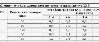
The power consumption, load current and supply voltage depend on the density of the crystals.
- Particle and moisture protection (IP) rating. The parameter ranges from 00 (no protection) to 68 (complete isolation). Thus, SDLs with IP20 are used indoors, for example, for interior lighting of furniture, and with IP67 - for external lighting of buildings, swimming pools and inside saunas/baths.
Particle and Moisture Protection Table
- Light flux color (monotonous/one-color or multi-color RGB strip).
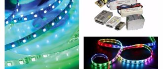
Characteristics of RGB strip
- Supply voltage. The board consists of groups of series-connected crystals that are connected in parallel to each other. Each crystal receives a supply voltage of no more than 3.3 Volts. Thus, knowing the density of the crystals, a supply voltage of 12 or 24 Volts is supplied to the board.
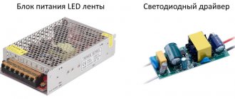
A special transformer installed between the SDL and the AC voltage source is responsible for building the required voltage level in the board. It supplies the required amount of electric current.
power unit
- Length of the supply cable line. The main rule is that the voltage drop of the supply cable should not exceed 8%. To do this, you need to calculate the load level and select a cable with the appropriate cross-section.
Permissible continuous current for wires and cords with rubber and polyvinyl chloride insulation with copper conductors
LED strip power calculation
The power consumption indicator directly depends on the density of crystals on the board:
| Density, pcs | Power consumption per 1 meter, W | Total power, W |
| 30 | 2,4 | The product of power consumption per 1 meter and the length of the board. For example, for a 3-meter tape with a density of 60, the power will be: 4.8*3=14.4 W. |
| 60 | 4,8 | |
| 120 | 9,6 | |
| 240 | 19,2 |
To select a power supply, the power value is 20 - 30% more than the power consumed by the board. For example:
LED strip with a density of 120 crystals per 1 meter. The total length of the SDL is 11 meters. Power consumption will be:
Plen = 9.6 * 11 = 105.6 W.
Pblock = 105.6 * 1.25 = 132 W.
Thus, the block with the closest power value is selected, this is 135 W. If you select a block with a power lower than the value that the board consumes, the latter will not light up. And the absence of a power reserve of 20-30% will lead to failure of the unit .
Common Mistakes
Quite often, beginning craftsmen connect 2 LED panels or more sequentially (directly 2 ends). However, this is wrong! The conductors between the segments have a thin cross-section, as they are designed for 1 piece of tape. When connected in series, there is a significant increase in resistance, which causes the lighting fixture to emit dimmer light. In addition, a higher current will pass through the first cut, which will lead to overheating of the tape and shorten its life.
To extend the life of the device, you need to connect them according to the correct circuit.
Features of installing LED strip
The process of installing the SDL does not require special professional skills, however, for its proper condition, you must follow the rules.
Installation occurs in several main steps:
- Preparation of SDL sites. The board is measured and cut in specially designated places.
Preparation of SDL sites
- Connecting board sections to each other. By soldering (a more reliable method) and using a connector.
Board connection methods (soldering and connector)
- Connecting a power supply or adapter.
How to connect the power supply and adapter
- Connecting a dimmer (controller) responsible for adjusting the light flux.
Example of connecting an RGB controller
Protect the benefits of power strips with fuses
But this is an important point. Suppose we have a powerful power supply, for example, 960 watts 24 volts. This is 40 amps. The power supply is of high quality; it can operate for a short time with an overload of up to 150%. Several tapes are connected to the unit at once, but some problem occurs in one of them, for example, the tape is flooded with water or it is partially shorted. If a short circuit occurs, the power supply will see it and turn off (this is called “short circuit protection”; most tape power supplies have it and, of course, all Meanwell units, among which there are models of this power). But if there is no short circuit, but the tape is partially closed, then the unit can supply a current of up to 60 amperes to this tape. With this current, the tape, the cable, and the amplifier will melt, and then short-circuit protection or overload protection of the unit itself will work. If the unit is turned off when the protection is triggered, after some time it will begin to turn on periodically, which is also quite bad.
You can install breakers on 24-volt lines. There are special machines for direct current (several times more expensive than regular ones); on the Internet you can find many discussions about how machines operate on direct current. My opinion is that DC circuit breakers work poorly. Not fast enough. Disconnection must occur instantly; even the minimum delay is unacceptable here. That's why I think fuses are the best option. For a cable with a cross section of 1.5 mm2 we put a 10 ampere fuse, for a cable with a cross section of 0.75 mm2 we put a 5 ampere fuse. We use the simplest fuses, 5x20. Such a blister of 10 pieces costs 120 rubles in Chip-Dip. You can find it cheaper on radio markets.
The fuses say “250 volts”, this does not mean that it only works with this voltage, it means that 250 volts is the maximum voltage for it. The fuse trips when the current is too high. The wire inside it is the thinnest point in our cable from the power supply to the tape; it will burn out first if the current is exceeded.
The fuse is conveniently inserted into the terminal on the DIN rail. The width of the ABB terminal is 8mm, the fuse is easily removed, you can quickly turn off the circuit by removing the fuse.
I have such fuses in my projects to protect all low-current cables coming from the switchboard: power supply to all drives and sensors, bus power supply. ABB has a model M 4/8.D2.SF with an additional feed-through second contact. There is a model M 4/8.D2.SFD with a 24-volt LED, which is used to monitor the integrity of the fuse and the presence of power.
A cheaper and simpler option is a regular fuse holder; it can be connected anywhere on the cable.
Such 1.25 ampere fuses are even included with Fibaro Dimmer dimmers so that you don’t forget to install them. In our case, the fuse rating is selected based on the maximum permissible current for the cable, possibly adjusted for the maximum current of the dimmer or amplifier.
When buying fuses, remember to spare. If you need 5 pieces, then buy at least 10, and preferably 20. It happens that by the time you figure out a problem, a dozen fuses have already burned out.
The fuse for each cable is convenient for us because it will immediately turn off the problematic branch, everything else will continue to work.
By the way, we put the fuse on the positive power supply of the tape.
Why do you need a power supply and controller?
The LED strip power supply is a device in the form of an aluminum/plastic/metal case, with terminals located on both sides.
Purpose: conversion of alternating electrical voltage of the network 220 V (input terminals) into direct voltage 12/24 V (output terminals), required for proper operation of the SDL.
A controller is a device that regulates the intensity of the glow of each diode, the total mixing of which produces a certain shade and brightness of the glow of the tape.
The controller can be controlled using the program embedded in it and/or manually - from the control panel.
When choosing a power supply and controller, it is important to calculate their power consumption, taking into account a 20-30% reserve.
What you need to connect
Not all novice craftsmen know how to connect an LED strip. To do this you need to prepare:
- A skein of flexible tape 5 m long. You can cut a suitable piece yourself.
- Power cable VVGng with three cores (section 1.5 mm²).
- Power supply with suitable power.
- Installation wire PuGV with PVC insulation.
- A profile with a protective sealed screen that diffuses light.
In addition, it is recommended to purchase a dimmer with a remote control.
Types of LED strip installation
LED strip installation is possible in several ways:
Aluminum profile. Its structure is pre-installed along the marked path, then a board with an adhesive base is glued into the channel itself. Afterwards, the entire structure is covered with a plastic profile, which creates a uniform dispersion of light.
The process of installing SDL using an aluminum profile
Pros : used for long high-power boards (more than 14 W); aluminum removes heat, thereby preventing the crystals from overheating, unlike plastic channels; smooth base and neat appearance.
Cons : higher price and time spent on profile installation.
Aluminum tape. It is attached along the intended path for attaching the board, then glue is applied to it, onto which the SDL is attached.
Pros : removes heat, ease of operation, used for small and medium power boards.
Minus : appearance.
Other fastening methods: plastic clamps, nylon ties, mounting clips.
These methods are applicable when the SDL is located in an invisible place, because visual perception deteriorates.
Double-sided tape and/or glue. One of the simple and reliable methods.
In all of these methods, the SDL is attached only along a straight path; if there are turns or corners, it is necessary to cut it and connect it using soldering or a connector.
How to glue LED strip
- Prepare the surface: smooth out any bumps, depressions, cracks, clean and degrease. Metal and plastic surfaces are degreased with acetone or white spirit; painted with vinegar. Wooden surfaces must also be varnished or painted.
- On the prepared surface, a marking (trajectory) of the SDL fastening is applied in a straight line.
- Stick the SDL using a convenient method:
- 3M double-sided acrylic tape is usually applied to the back of the board. Gradually opening the adhesive side, it is pressed tightly against the treated surface.
Fastening the tape with double-sided tape (self-adhesive base)
- Glue (super glue, instant installation, liquid nails). It is applied along the trajectory in small portions every 5 – 10 cm. Then the SDL is pressed tightly and fixed.
Pros: quick contact and grip.
Minus : lack of heat dissipation properties, which leads to overheating of the crystals.
Tape cutting and joining
Tape cutting is necessary in the following cases:
- level changes (corners, turns);
- shortening to the required length.
Cutting is carried out with scissors in the location indicated on the board (dotted tape and/or scissors icon). A cut in the wrong place will disrupt the nutritional pattern.
Place of cut designation on various tapes
To connect/extend/extend the SDL, two main methods are used: soldering or a connector (section “Connecting power using an LED connector”, “Connecting power using soldering”).
Connection methods
The connection of the LED strip to the power supply is serial. Therefore, we pay attention to the polarity: we connect “+” only to the same pole, and “-” to the minus.
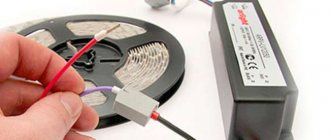
At the end of the tape that comes on a reel, conductors are soldered. If the glow is monochrome, there are two conductors - “+” and “-“, for multi-color ones there are 4, - one common “positive” (+V) and three colored ones (R - red, G - green, B - blue).
Bobbins in their purest form
But a 5-meter piece is not always needed. shorter lengths are often required. Cut the tape along the marked lines.
Cutting lines on LED strips
In the photo you see contact pads on both sides of the cut line. They are labeled on each tape, so it’s quite difficult to get confused when connecting. To make it even easier, use wires of different colors. It will be clearer this way and you definitely won’t get confused.
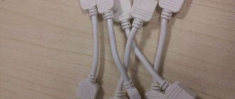
Connectors
You can connect the LED strip without soldering. There are special connectors for this. These are specially designed devices - plastic housings that ensure proper contact. There are connectors:
- for connecting conductors to the strip;
- connection of two tapes. Different types of connectors
Everything is very simple: open the lid, insert a tape or conductors with bare ends. The lid closes. The connection is ready.
The method is very simple, but not very reliable. Contact is ensured only by pressure, and if the cap is loosened a little, problems begin.
Soldering
If you have any soldering skills, it is better to use this method. To work, you will need a soldering iron of medium power, with a thin or sharpened tip. You need rosin or flux, as well as tin or solder.
We strip the ends of the conductors from insulation and twist them into a tight bundle. We take a heated soldering iron, lay the conductor on the rosin, and warm it up. We take a little solder onto the soldering iron tip and warm up the wires again. The veins should be covered with tin - tinned. In this form, the conductors are easy to solder.
How to connect a diode strip
It is advisable to tin the contact pads in the same way: dip the soldering iron in rosin and warm up the pad. Make sure that tin does not leak beyond the pads. Take the prepared conductor, place it on the pad, and heat it with a soldering iron. The tin should melt and tighten the conductor. Hold the conductor in place for 10-20 seconds (sometimes it’s easier to hold it with thin-nose pliers or tweezers - the conductor gets hot), tug. He must hold on tight. Similarly, we solder all the necessary conductors.
On RGB strips with 4 wires, make sure that the pads do not connect during soldering. The distance between the contacts is very small, the slightest drip can ruin the whole thing. Proceed carefully.
Watch the process of soldering the diode strip in the video. You will need to repeat everything.
Recommendations for placement of equipment and installation of LED strip
- Determine for yourself the method of installing the SDL. This is important when choosing it, because Not all SDLs are equipped with self-adhesive tape. In this case, they are attached to brackets and clamps.
- Carefully prepare the surface on which the tape will be applied. For more reliable fixation, additionally cover the entire path with double-sided or aluminum tape and apply instant glue.
- During the gluing process, the protective coating of the self-adhesive layer is removed gradually as it progresses.
- In order to save money, the plastic profile of aluminum channels can be replaced with a plastic corner. It is attached with glue/liquid nails.
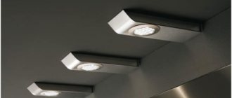
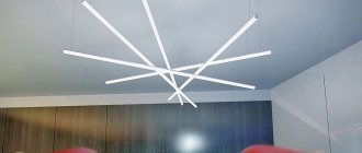
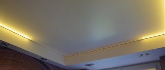
- When designing ceiling lighting, remember the degree of light dispersion. For the most effective lighting, the distance from the ceiling to the mounting location of the board should be at least 80 mm.
- To illuminate signs, display cases, and cabinet shelves, choose side-illuminated SDLs. This will help avoid being blinded by crystals and highlight the required interior details.
- Boards longer than 5 meters are connected to the power source in parallel. Otherwise, it will lead to damage to the diodes.
- PSUs equipped with a fan have a specific sound. Therefore, it is worth considering the location of its installation outside recreation areas. The controller, on the contrary, should be located nearby for ease of control from the remote control or manually.
- Choose trusted manufacturing plants. This will help you avoid unnecessary expenses.
How to do without a power source
If it is not possible to install a power supply, there are two options:
- use a tape rated for 220 V;
- power a low-voltage lamp without a transformer through a ballast element that limits the current and absorbs excess voltage.
In the first case, you cannot directly connect the LED device to the AC network . An LED, as a semiconductor device, will only transmit the positive part of the sine wave. But during a negative voltage, a reverse voltage will be applied to it, for which the LED or chain is not designed for. Therefore, the life of the lighting device will be short. It must be connected via a rectifier. Better across the pavement. The diodes must withstand the full current of the strip and a reverse voltage of at least 320 V.
Connecting the lamp via a rectifier.
This also applies to the second option, but here you will still need an additional resistor. Its resistance is calculated using the following method:
- The operating current is found using the formula I = Rud*L/Unom , where: Rud is the specific power consumed by 1 meter of tape, W; L – total length of the LED strip, m; Unom – rated voltage of the luminaire (12..36 V).
- The voltage drop across the ballast is determined Ubal=310-Unom , where 310 is the amplitude value of the voltage in the network.
- The ballast resistance is R=Ubal/I. If the current is in amperes, then the resistance will be in ohms.
- The resistor power is calculated as Рres = Ubal*I. The nearest larger value of the standard power series is taken.
Connection diagram with quenching resistor.
The calculation is somewhat simplified; the resistance of the LED in the open state is not taken into account. But for practice the accuracy is sufficient.
Expert advice
Starikov Mikhail
Senior Electronics Engineer
Ask a Question
This method has two disadvantages. All elements of the tape, when connected to the network, will be under a voltage of 220 V. It should also be borne in mind that the calculation relates to the specific length of a particular tape. When replacing a luminaire or changing the total length, the ballast must be calculated again.
Instead of a resistor, you can install a capacitor. The advantage is that it will not heat up. Capacity is calculated using the following formula:
С=4.45*I/(310 - Unom) , where:
- C – required capacitance in microfarads;
- I is the operating current found earlier;
- 310 – amplitude voltage of the network in volts;
- Unom – rated voltage of the luminaire (12..36 V).
But additional elements will appear in the scheme:
- R1 – resistor for discharging the capacitor after removing the power;
- R2 – to limit the inrush current on the capacitor charge at the moment of switching on.
Connection diagram with ballast capacitor.
The value of the first resistor is several hundred kilo-ohms, the second – several tens of ohms.
Basic errors in connecting tapes
Mistake No. 1 – the security level of the tape is not selected correctly. For example, the use of boards with an IP20 rating is unacceptable in rooms with high humidity and in open spaces. When used in baths and bathrooms, a short circuit and electric shock may occur to a person.
Error No. 2 – the power of the power supply is not calculated correctly. It is important to follow the rule of 30% power reserve. This will allow in the future to connect additional sections or replace them with more powerful ones.
Mistake #3 – sequential connection of new sections. As mentioned above, each new tape is connected in parallel to the power source.
Error No. 4 – lack of heat sink elements. Tapes with a power of over 14 W are installed only on an aluminum profile, SDL with a power of 6 to 14 W are installed on metal tape. They perform the function of transferring heat from heating the crystals to the external environment.
Incorrect connection
Diagram of incorrect serial connection of two LED sections:
Diagram of incorrect (serial) connection of two tapes
The connection in series leads to an uneven glow of the tracks and overheating of the beginning of the tape. Therefore, each section longer than 5 meters is connected in parallel :
Example of parallel connection with 1 block and two
When the power of the tape section is above 9.6 V, it is recommended to make a parallel connection on both sides of the section. This guarantees a stable, uniform light output.
Example of two-way connection of a section
Incorrect mounting (location)
When installing, pay attention to the external environment. There should be no devices or factors nearby (within at least 0.6 m) that cause additional heating of the elements (heating system, incandescent lamps, kitchen heating appliances, sunlight, etc.). Optimal operating temperature is +40 0C.
The path for laying the SDL must be cleared of unnecessary objects. During operation, the board should not touch additional objects or have unnatural corners or bends (unless they are made by soldering or a connector).
Selecting a Power Source
Switching power supply.
There are two main requirements for the power supply:
- its output voltage must correspond to the supply voltage of the lighting device;
- the power must provide power to the tape with a reserve.
Power is calculated using a simple formula:
Rbp=Rud*L*Kzap , where:
- Rbp – estimated power of the power supply, W;
- Ore – specific power consumed by 1 meter of tape, W;
- L – total length of the LED strip, m;
- Kzap – safety factor, taken equal to 1.2..1.4.
Important! As a result of the calculation, in most cases, the result will be power that does not fall within the standard range of power ratings of the power supply. You should round to the nearest higher value.
You also need to select the source version:
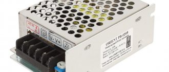
- hermetically sealed - suitable for use outdoors (it is irrational to use inside - such modules need better conditions for natural cooling);
- unsealed - usually installed indoors.
Safety precautions
- All installation work is carried out with the power turned off.
- When installing the SDL on a conductive surface, the attachment point is pre-insulated.
- Observe polarity when connecting contacts; multi-colored conductors help with this.
- Do not touch exposed conductive parts while the power is on.
- Do not expose the board to mechanical stress (kinks).
- Follow electrical safety rules when working with 220 V networks.
- Related Posts
- LED warehouse lighting: selection, calculation and installation
- Eliminating the cause of blinking and flickering LED lamps
- What are gas discharge lamps
Calculation of the cross-section of connecting wires
The cross-section of the conductors should not be less than permissible - this leads to overheating and subsequent problems. Too large a cross-section means financial costs and inconvenience of installation. The current on the low voltage side can be calculated knowing the total power consumed (Ptotal) and the operating voltage of the tape:
I=Ptotal/Uwork.
| Conductor cross-section, sq. mm | 0,5 | 0,75 | 1 | 1,2 | 1,5 |
| Allowable current, A | 11 | 15 | 17 | 20 | 23 |
The current from the 220 V side is calculated by the formula I220 = Ilow * (U tape / 220 V , where:
- I220 – current from the 220 volt side;
- Ilow – lamp current;
- U tape – the supply voltage of the lamp.
You also need to take a small safety factor for the efficiency of the power supply.
Important! For outdoor installation, the cross-section of the conductors must provide not only the required economic current density, but also mechanical strength.
Battery powered
This connection option allows you not to use electricity, which is convenient in some circumstances. Powering the LED device from batteries is possible if you plan to connect a short section with low power for short-term use. In this way, you can connect duralight, for example, to illuminate shelves, pictures or a work surface in the kitchen.
Any batteries will do; their total voltage should be from 8 to 12 V.
The work order is as follows.
- Strip the contacts on the batteries, tin the ends of the wires and solder them to the plus and minus of the battery, respectively.
- When connecting the toggle switch, the plus from the battery is connected to its input, and the output is connected to the minus of the duralight.
- Solder the free ends of the contacts to the tape, remembering the polarity.
LED strip connected to a battery.
Connection diagram via controller
A controller or dimmer is needed to control lighting, for example, adjust brightness, turn on/off individual sections of the tape, and create lighting effects. Depending on the desired result, you can install the controller on the wall or use a flush-mounted device.
Connection diagram for LED strip with controller.
You can choose the control method:
- turning;
- button;
- sensory;
- remote controlled.
When choosing a device, read its characteristics. So, the power of duralight should be less than the values indicated on the controller body. In the electrical circuit, the dimmer must be placed between the power supply and the tape itself and the connection must be made, remembering to observe the polarity.
A monochrome strip is connected to the dimmer with 2 wires; when connecting an RGB strip, a connection is made with 4 contacts, each to its own socket.
Use via computer
Duralight can be used to illuminate the workplace. In this case, you don’t have to connect it to a power outlet or through a switch and use the device without a power supply; just connect the LED strip directly to the computer. This can be done in several ways.
Via USB connector
Most standard duralights require a supply voltage of 12 V or 24 V, while the USB port has a voltage of 5 V with a permissible current of up to 500 mA.
The easiest option in this case is to purchase a non-standard 5-volt duralight with a connector for a USB connection (for example, made in China); it can be connected to any device equipped with a USB port.
A more complicated way is to use a step-up voltage converter from 5 V to 12 V; you can purchase it or make it yourself. When assembling with your own hands, you can use the LM3488 integrated circuit; all the necessary information on assembly is indicated in the instructions for it.
The option using USB is the only possible one for connecting to a laptop; there are other less labor-intensive methods for powering it from the system unit of a desktop computer.
Via one of the molex connectors
There are several of these connectors in the PC; they are located under the side cover of the system unit and have 4 contacts with insulation color coding - yellow (+12 V), 2 black (GND) and red (+5 V). To connect the LED strip, yellow and 1 of the black wires are used. To make the connection detachable, you can use a MOLEX-SATA adapter. To connect duralight, the following steps are required.
- Turn off the computer and remove the side cover of the system unit.
- Remove the SATA plug from the adapter; it will not be needed.
- Solder a duralight contact with a “-” sign to the free ends of 1 of the black wires, and a contact with a “+” sign to the yellow one.
- Cut or insulate the remaining black and red pins.
- Find an unused molex connector and connect it to the adapter to test turn on the duralight.
Direct to motherboard
Some PC models allow you to connect the LED strip to the corresponding connector on the motherboard, but not every device has it. The easiest and most convenient way to connect duralight to the motherboard is to purchase a ready-made installation kit, which includes an RGB strip and all installation components.
The main thing is to make sure that your computer allows this connection option.