Living comfort consists of many components, among which lighting system control plays an important role. It can be made more convenient by installing two-key electrical appliances.
Agree, it would be nice to learn how to do this kind of work yourself, especially if you have to do a major home renovation and update the electrical wiring. But before you connect a double switch to two light bulbs, you need to decide on the circuit and study the procedure.
We will help you achieve your plans. The article describes the nuances of implementing different connection schemes, and also provides step-by-step instructions for installing a two-key switch. The text material is supplemented with visual illustrations and video reviews.
Pros and cons of dual connection
An experienced electrician begins any project to improve a lighting system by optimizing the use of all electrical devices combined into one chain.
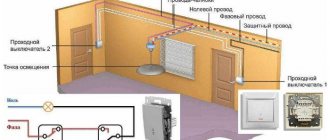
An example of an optimized circuit is the traditional lighting arrangement of the “toilet + bathroom” block. On the corridor side, one switch is usually installed, but with two keys.
Thus, the lamp in the bathroom is controlled by one key, and the light bulb in the toilet is controlled by a second. With one movement of your hand, you can perform two actions at once, turning off the lights in one room and turning on the lights in the next one, which is very convenient.
If the switch is installed in the wall between two parts of the bathroom, then choosing a key will not be difficult - it will be located on the side of the desired room
Installing a common switch for two rooms is advisable if they are located nearby. For rooms remote from each other, it is reasonable to use separate electrical installations.
A double switch may also be required when installing a chandelier or sconce with two bulbs. Separate control expands the functionality of the lighting device and allows you to increase or decrease the combustion intensity.
If you press one key, the lighting will be inadequate; when you press both keys, it becomes twice as bright.
To save energy, it is not necessary to use both bulbs at the same time. To create a relaxing atmosphere, it is enough to turn on only one of them
As you can see, the ability to connect a double switch to two separate light bulbs makes it easier to control lighting fixtures or adjust light intensity. When installing a single device for two rooms, not only electricity is saved, but the number of installation materials and devices is reduced.
Useful tips
- Calculate in advance the required (sufficient) cross-section and length of the wires depending on the power of the light sources. The cross-section cannot be less than one and a half square millimeters.
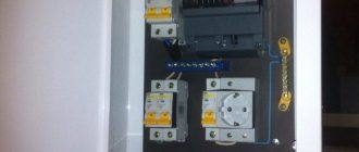
- In addition to the distribution box, it is also recommended to purchase an additional protective device that will protect against short circuits and overloads in the electrical network.
- Choose terminal switches rather than those with screw-in screws, as the first connection option is stronger and more durable: the screws will need to be tightened after a while.
- You can adjust the lighting using a single-key device! But for this, additional equipment is purchased and installed - the so-called dimmer.
- If you install a similar structure to illuminate a bathroom or other damp place, do not mount the switch indoors under any circumstances.
- Note: if the switch is modular, then there is always another one near the input terminal. These two terminals must be connected to each other with a separate wire.
- All connections and connections are strictly prohibited outside special junction boxes. And in the case of complicated environmental conditions, additional protection must be made (for example, from water, humidity, ingress of other solid and liquid substances).
- If you install a switch, for example, for a toilet, then one of the keys can turn on the light in this room, and the other can turn on the hood.
Connecting a switch that controls the light with two keys is not difficult if you strictly follow the instructions given above. Read all the instructions and useful tips first so that you don’t miss anything, then everything will work out!
How to choose a circuit for two light bulbs
There are differences in the connection of 1-key and 2-key switches. To better understand the difference, let's first look at the installation nuances of a single-keyboard player.
You can connect one or more light bulbs to a regular switch with a single key - the principle remains the same.
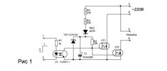
The diagram shows an option using a two-core cable, without using ground. The neutral core is pulled directly to the lighting fixture, and the phase is connected to the switch, from where it goes to the light bulbs (+)
This is the simplest scheme; it is traditionally used if simple control of a lamp or an entire group is needed. When the electrical installation is turned on, all involved light sources light up. If there is a chandelier or sconce with two lamps, then both will turn on at once; it will not be possible to use them one at a time.
Now let’s look at what changes if a single-key device is replaced with a two-key device. The first circuit for connecting a double switch to two separate light bulbs is relevant for the TN-C system, which is still found in old houses. For the lighting circuit, two-core wires are used.
The zero is sent through the junction box directly to the lamps connected in series, and the phase goes to the input terminal of the switch. But the output is already double: a phase conductor goes from each of the output terminals to a separate lamp (+)
It turns out that you can use either one or both light bulbs at the same time, using either one or two keys.
A positive point is the ability to change the lighting intensity in one room. If the lamps are in different rooms, then you can turn on the lights in each room separately or in both at once.
In new houses, grounding systems that differ in design are used, for example, TN-S. The difference between the second scheme for a home electrical network is that a three-wire wire is required: the third wire is the “ground”.
Like the neutral conductor, the grounding conductor is sent to the distribution box, and then connected to the wires of the lamps and connected to metal parts (+)
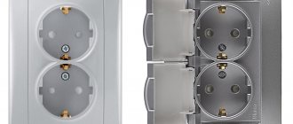
The grounding wire is connected differently if there is an outlet in the same block as the switch. Then the “ground” from the electrical panel reaches to the distribution box, and from there to the outlet.
Preparatory work
When working with electrical equipment, extreme precision and caution must be observed, therefore all materials and tools needed for the work must be prepared and purchased in advance:
- flat and Phillips screwdriver;
- pliers;
- side cutters;
- insulating tape;
- a good construction knife with a sharp blade (for stripping wire ends);
- for crimping it is more convenient to use a special tool - a crimper (it is not necessary if the wires are not stranded);
- switch;
- wires.
Attention! It is very important to turn off the power supply before starting work!
It is extremely important (especially for non-professionals) to correctly draw the connection diagram and lay out the wiring in advance.
The circuit should include the following three wires:
- Ground wire (exited to the light source, indicated on the diagram as “0” or with an arrow pointing down).
- Neutral wire (also led to the light source, designated by the letter “N”).
- Phase is a live wire that, when turned on, should provide power to the light bulbs (the terminals for the phase wire are designated by the Latin letter “L”).
You can install the wiring in one of two possible ways: open or closed. For the first, you will need additional materials - corrugated pipes or grooves, for the second - you need to cut grooves in the walls.
Please note that wiring is done before plastering the walls and ceiling. This means that only after all the wires have been laid and are sufficiently insulated, you can begin finishing work.
To make a small recess under the switch, you will also have to use a chisel and a hammer (this is not necessary if the switch will be installed in the old place).
What is an RCD in electrical engineering: types, principle of operation
How to connect a pass-through switch: connection diagrams
Step-by-step installation instructions
Conventionally, connecting a switching device can be divided into several stages. They start with the cables: if the wiring is old, then it definitely requires replacement.
Then you need to correctly connect the wires in the junction box, and finally in the switch mechanism. To install a chandelier or lamp, you usually use the instructions provided by the manufacturer.
Stage #1 – preparing the walls
It is recommended to skip the wall gating stage only if new wiring with copper conductors of a suitable cross-section has already been laid. When in doubt, it is best to consult an electrician.
For the lighting group, a regular VVGng wire with a cross section of 1.5 mm² is suitable. If sockets are connected along with lighting, then it is better to immediately take the same wire, but 2.5 mm².
The preparation of the walls includes gating, arrangement of installation sites for socket boxes and distribution boxes. At the same stage, you can install an additional circuit breaker in the electrical panel.
A separate protective device will come in handy when the lighting line requires repair - only one circuit can be turned off, the rest will work as usual.
The grooves are knocked out with a hammer drill, a circular saw, or even manually, but to cut even grooves, a special tool is used - a wall chaser equipped with a vacuum cleaner
The lighting system of a wooden house differs in the type of wiring. The hidden method is not used, since it is extremely fire hazardous and requires maximum cable insulation.
The wires are mounted from the outside on special insulators. Instead of internal switches, overhead switches are installed, but the principle of connecting the cores to the terminals does not change.
After gating of concrete, brick, and aerated concrete walls, the grooves in which the wires are laid are sealed with mortar or alabaster. Then you can plaster and decorate the walls, but it is better to save the location of the wires in a drawing or diagram - until the next repair.
Stage #2 – connection in the distribution box
The distribution box is the chamber where the wiring and connection of the wires takes place. When installing switches or sockets of different types, the connection diagram changes.
But first you need to choose the right junction box. Previously, metal products were used, but now they produce safer and easier-to-install plastic analogues.
There are internal and external models, but it is always easier and more efficient to work with external ones. If you need to urgently disconnect the wires due to replacing the electrical installation, then to access the built-in junction box you will have to dismantle the plaster and then make repairs.
The body of the external model is always visible: just unscrew the cover and perform the necessary actions.
The connection diagram of the cores is simple: the neutral wire from the panel is twisted with the zeros of the two connected lamps, and the phase is sent to the switch. Two output phases from the switch go to the lamps - one for each
If the wire is three-core – and now this is what is most often used – then in the junction box, similar to the neutral conductor, the “ground” is twisted. And if the wiring is old, but reliable, then there is no point in changing it, and you need to use the connection indicated in the schematic image.
There are several ways to connect wires. The most common are twisting followed by insulation and the use of terminals.
Soldering is used extremely rarely. If you are used to using terminal blocks, then you can consider the option of a distribution box with pre-installed terminals.
Stage #3 – installation of lamps
How to install a chandelier with two lamps or two separate lamps depends on many factors:
- lighting fixture models;
- wiring readiness;
- basics for installation.
The easiest way to change lighting equipment is when the wire is routed out at the installation location, for example, in the center of the room.
To install a chandelier, you need to perform two operations: hang the lighting fixture on a hook or bracket and connect the wires correctly
If the ceiling is new and is a suspended structure (tension, plastic or plasterboard), then additional fasteners or mortgages should be installed to install the chandelier.
When two phase wires are supplied from a two-key switch to the lamp, they are connected alternately - each to its own lamp. Also, two neutral wires are pulled from the distribution box - they are also scattered among different lamps.
If both bulbs are connected to the same wire, they will turn on/off at the same time, and there is no point in installing a double switch.
When installing two separate lamps in different rooms, the connection principle remains the same, only the routing of the wires from the junction box changes - they are directed in different directions. As a rule, the rooms are located next door. It is better to mount the distribution box above the switch, approximately 15-20 cm from the ceiling.
Stage #4 - installation of the switch
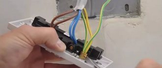
There are no difficulties in either installation or connecting the two-keyboard. It is installed in a socket box or directly into the wall, secured with claws or a screw connection. Exactly how the wires are connected is shown in the photo.
The double switch is always connected only to the phase conductor coming from the distribution box, where it comes from the electrical panel. The core is inserted into the terminal marked “phase L”. From the output contacts L1 and L2, the phase conductors go to the lamps (+)
If the chandelier has not two, but more lamps, which is much more common, then the connection is made in groups. All lamps are divided into two equal or unequal groups, and then the wire from contact L1 is directed to one, and the wire from contact L2 to the second.
Conditional division into groups is made depending on the desired degree of illumination of the room. If you need two intensity modes, weak and bright, then you can connect the first core to one lamp, and the second to the rest. To reach the maximum brightness level, just press both keys.
Design Features
Two-key devices for turning on/off the load are structurally almost identical to single-key devices, the main difference lies in the switching mechanism. Below, Figure 2 shows the main design elements.
Figure 2. Main design elements
Designations in the photo:
- A – keys;
- B – external panel-casing;
- C – internal panel;
- D – switching mechanism;
- 1 – input;
- 2 and 3 – contacts for control wires going to the chandelier.
Now let's look at how the contact group diagram of the switching mechanism is arranged; it is shown in Figure 3.
Drawing. 3. Contact diagram of a two-key device
As can be seen from the presented diagram, the switching mechanism has three contacts, “1” is a common input, “2” and “3” are two control outputs.
Now that we have figured out the design of two-key switches, we can move on to their connection diagram.
A few words about electric current
Without “loading” with theory and complex physical concepts, let us recall the elementary basics of electrics. The household electrical network has a voltage of 220 V, the type of current is alternating. What does it mean? One of the contacts, “phase,” has a constantly changing potential from “+” to “−” (50 cycles per second), and the other “zero” serves as a kind of battery, allowing electrons to either accumulate in excess or flow back.
Each lamp has two contacts: base and central. In order for our lighting device to start working, zero and phase must be connected to these two contacts. Moreover, in the case of alternating current and a regular household lamp, polarity does not play any role.
But it is still necessary to know the location of “zero” and “phase”. There is a special device - a “probe”, which is used to determine which of the wires is phase. This must be kept in mind for the correct inclusion of a disconnecting device - a switch - in the circuit. It must necessarily break the “phase”, these are the safety requirements.
What are the differences between the elements responsible for connecting the wiring?
Switches equipped with self-clamping terminals are more convenient for carrying out work. To fix the wire, you just need to strip it and secure it in the terminal. In the clamps, the cable has to be pressed with a screw. Moreover, over time the connection may weaken. You have to periodically check and tighten the screw if necessary.
The switch housing can be made of plastic or ceramic. The second option is used for heavy loads.
Some switch models have built-in backlighting. It is convenient if you need to find a device to turn on the light in a dark room.
Installation Safety Precautions
Here is a set of some standard rules to avoid trouble when installing lighting fixtures:
- The switch cannot be set to “zero”; it must always break the “phase”. Only in this case the switch is in the “off” position. allows you to carry out any repair work on the lamp, including replacing it, without cutting off power to the entire house.
- When making a twisted connection of wires in a junction box, under no circumstances should aluminum and copper wires be connected to each other. Metals with different potentials form a galvanic couple; the contact will weaken over time and begin to “spark.” Sometimes this leads to fires.
- Before starting work, you should stock up on a tester to determine the phase wire and, just in case, thick rubber gloves.
- You should not cover open wiring (either double insulated or triple insulated, it doesn’t matter) with paper wallpaper or other flammable finishing materials.
- Do not use used wiring. It is unknown what loads it was subjected to in the past, and it is impossible to check the condition of each core inside the braid along its entire length.