06/30/2016 master
In the world today, the most popular types of lighting are various LED products. And the most widely used LED products are LED strips.
Such products have become an excellent alternative to other lamps because they have many positive qualities, among which low energy consumption, as well as a long service life, should be highlighted. But there are situations when the LED strip needs to be checked for functionality. In this case, the good thing is that all the necessary manipulations can be carried out at home and avoid buying a new LED strip. This will be discussed further.
Features of the tape and its main component - LED
Light-emitting diode
LED strip today is one of the most profitable light sources. It is based on an LED, which resembles a small light bulb. Although in reality this is not the case. The design of an LED allows it to transmit electricity in only one direction while emitting light. The LED can only operate from a DC power source.
An LED is a semiconductor with an electron-hole pn junction, as well as a metal-semiconductor contact capable of generating optical radiation. The most important element of such a diode is the pn junction. This transition has the form of two parts of a semiconductor, characterized by different types of conductivity. The “n-type” end has an excess of electrons, and the “p-type” end has an excess of holes. In a situation where you apply “forward bias” to the p-n junction (connect a power source), current will begin to flow through it. At the heart of any LED strip is a diode. LED strips are a light source in which LEDs are arranged in series and on a flexible basis.
Tape section
In addition to the LEDs applied to a special base and connected to each other, the LED strip also includes a resistor. All LED products are characterized by low voltage. Therefore, the LEDs in the strip are placed three in one group. They are connected in series and terminated with a limiting resistor. This is due to the fact that such products can be cut into pieces of the required size only in certain places, which are indicated on the tape with a scissors symbol. There are such areas on every 5 cm of the base. Any LED strip should be connected to a power supply.
Note! Each product requires its own power supply. The required power for the power supply should be calculated based on the power consumption of the tape itself and the additional power used for reserve.
Knowledge of the structure of the strip and LED is necessary in a situation where they need to be tested for functionality. Without knowledge of the structure, it is difficult to understand how and with what you can check the operation of a particular LED product at home.
Infrared
As we acquire consumer electronic devices, each of us gradually becomes the owner of a whole battery of remote controls. As long as the equipment obediently responds to your commands, there is nothing to worry about.
But it is quite possible that desperate attempts to change the channel or turn down the brightness of the chandelier do not lead to any result. In such cases, first check the status of the infrared LED, through which the remote control transmits your requirements to the main device.
Read also: Wrought iron benches for a cemetery
There are several ways to check the IR LED in a remote control or other device. Let's start with the simplest:
If you don’t have a gadget capable of removing it, the suspected LED can be removed by replacing it with a super-bright or SMD-type LED. Just make sure that the operating voltage of both elements is the same.
If the test LED emits visible light when pressing buttons on the remote control (most likely, it will be dim), then the IR LED has already served its purpose.
A more complicated method, but it does not require a camera or soldering. You can use an infrared photodiode. When infrared radiation hits the sensor of this element, a potential difference is formed at its terminals.
If pulse curves appear on the device screen, the LED under test is in working condition. If you observe complete calm, then it’s time to buy a new IR LED.
Advantages and disadvantages of such LED products
LED strip is used today in a wide variety of fields due to its following advantages:
- the ability to give the product a variety of shapes;
Curved LED lighting
- the ability to install the product on any surface, as it is equipped with a self-adhesive base;
- the ability to increase the length of the product in an unlimited size;
- the ability to cut the tape to the desired size;
- high-quality luminous flux provided by LEDs;
- long service life;
- Possibility of use in rooms with high humidity;
Note! In rooms where there is high humidity, only waterproof products should be used.
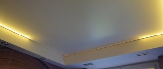
- the ability to use such a tape to create a wide variety of lighting designs that can be used both inside and outside buildings.
But in addition to the above-described advantages of this LED product, it also has some disadvantages:
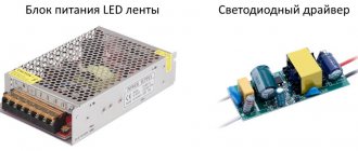
Power supply for LED strip
- quite high cost;
- the need to connect a power supply to the tape. In this case, the power supply can act as one of the weak links in the performance of a lighting system of this type. Very often, it is the power supply that should be checked for functionality in order to exclude incorrect functioning of the tape itself.
It is worth noting that the power supply in such a lighting system plays a leading role, since it ensures that the 220 V network voltage drops to the required level required to power the LED strip. And it may require a power supply of 12 or 24 V. Therefore, an incorrectly selected unit can lead to a decrease in the performance of the tape.
Rare cases of malfunctions
Tapes receiving 12/24V power supply have small sections of 3 diodes. This reduces the time spent searching for a faulty area and element. Subsequently, the burnt-out section is removed, and the sections of the board are connected to each other. Or a new section is soldered.
LED boards that operate directly from a 220 V network have an excellent design. All diodes on it are connected in series, its length reaches 1 meter (60 elements). This makes it difficult to find a non-working element and repair it.
If one diode fails, the entire section goes out. To find it, use the shunt method, i.e. create an artificial jumper through which the operating current passes, bypassing the faulty area.
Bypassing the faulty area
Then the faulty crystal is removed and a new one is soldered or a jumper remains.
Options for assessing the performance of LED products
Due to the fact that LED backlighting has a complex organization, its functionality can be tested in several ways. The choice of method depends on what exactly is worth checking for performance at home. The following elements of the lighting system can be checked for functionality:
- the LED strip itself;
- specific LED;
- power supply connected to the tape. It is worth noting that when the product is powered using several converters (power supplies), each of them must be checked for functionality.
Let's look at each option in more detail.
Main conclusions
Repairing an LED structure is not as difficult as finding the cause and location of the problem. There are typical problems:
- flicker;
- stopping the lighting of the entire backlight or one part;
- brightness reduction;
- disappearance of one or two colors in RGB lamps.
All of these faults are caused either by problems with the power supply or by faulty LEDs. Repair consists of replacing problematic components or individual elements, as well as restoring contact with the power supply or connector. Share your repair methods in the comments.
Previous
LEDsRequirements, characteristics and best manufacturers of waterproof lamps
Next
LEDs Do-it-yourself computer lighting: diagrams, instructions, necessary materials
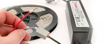
Checking the LED strip
Despite the fact that LED products (strips and light bulbs) are characterized by a long service life, they may stop functioning much earlier than the period specified by the manufacturer.
Working LED strip
In principle, you can understand whether the tape is working or not by simply connecting the power supply to it and supplying the amount of current required for operation. If the product glows evenly and brightly, then everything is in order. But if this does not happen, then you need to use a multimeter. Testing LED products of this type for performance with a multimeter is a fairly simple way to evaluate.
Note! In this situation, it is assumed that the power supply has previously been tested for functionality and found to be suitable for use.
To check the tape with a multimeter at home, you need to do the following:
- We “ring” the wires feeding the tape with a multimeter, since a local break is possible. For example, one wire may simply fall off due to the fact that it was poorly soldered during the circuit assembly stage;
- If there is no damage to the wires, then the whole problem is in the LED strip.
Such a conclusion may mean that the purchased products were of poor quality, there were violations in the assembly of the working circuit, or violations of the operating conditions of the house.
Broken track
Quite rarely, but such a malfunction as damage to current-carrying paths occurs. The SMD elements will be intact, but the entire backlight section, starting from the point where the track breaks, will not glow.
This can happen if you bend the LED strip at arbitrary angles without connectors or wires.
The test is done by the tester in dialing mode. Each section from one point (plus and minus) to another is called for integrity or breakage.
As you can see, finding the cause of the malfunction or, conversely, making sure that the LED strip is working, with just a tester or battery at hand at home, is not such a difficult task.
Checking for proper LED operation
Multimeter
There are situations when one specific LED fails. Current can no longer flow through it, resulting in a break in the serial connection and the LED strip does not light up. The most striking analogue of this situation is a Christmas tree garland, which also stops lighting when one bulb fails.
You should also use a multimeter here. But it must have a special function for this - “diode check”. This function may have a separate designation on the device body. When using this equipment, as a result of passing voltage through the desired LED, it can light up slightly if the positive at the output of the multimeter coincides with the anode on the diode. Such a check involves the following actions:
- If the polarity is observed, the display of the measuring device after connection will display the voltage drop on the direct junction. The required number can be found in the accompanying documentation of the diode;
- if reverse polarity occurred, the multimeter will show one. This will indicate that the LED is working properly.
Note! The presence on the display of a measuring device of a value different from one will indicate an existing malfunction.
This principle will remain unchanged in the situation of assessing the performance of both one individual LED and as part of an entire system or strip. You should know that this element needs to be checked in both directions in order to fully assess the correctness of its operation. When an LED passes electricity in both directions, this also indicates a malfunction.
Design
An LED is a semiconductor element similar in design to a diode. When current passes through the LED, optical radiation visible to the eye is created. This part consists of:
This is the standard design for lamps of all shapes. To achieve brightness, manufacturers only increase the number of layers or the number of crystals. These values directly affect power.
Checking the converter for serviceability
If the two methods listed above did not show the cause of the LED strip failure, then you should check the power supply. In such a situation, there is a very high probability that it was he who failed. Note! Many experts recommend checking the power supply for serviceability immediately when the light source stops working.
Types of power supplies
Typically, you can determine that the power supply is not working based on several signs:
- When it is connected to the network, the green LED does not light up, which indicates its operation. But here a situation may arise when the unit itself is working normally, but the LED is broken;
- when the converter is turned on, there is no characteristic noise;
- When you connect a multimeter to it, the measuring device shows that there is no voltage at the output. In such a situation, the display will display zero.
When you have found out that the “root of evil” is located in the power supply, then you have three ways to solve the problem:
- buy a new converter. But it is worth remembering that this is by no means a cheap device. Therefore, replacing it will cost you a pretty penny;
- give it away for repair. Here you also need to be careful, since the final cost of repair work will depend on what exactly broke/burnt out. Sometimes it's better to buy a new power supply than to pay almost the same amount to repair an old one that may become damaged again in the near future;
- repair the converter yourself. For people who understand radio engineering, this will be the best option. This way you will save your money and be able to repair the old power supply if possible.
Which option you choose depends on your financial capabilities and knowledge in the field of radio electronics.
Power determination
The operating power of the LED is necessary for its correct connection to the operating circuit of any device. Many people are faced with the problem of how to find out the power of an LED without markings on the case or packaging. There are 2 ways to determine this parameter.
Visually
LEDs are produced in a variety of sizes and colors. By color and size you can find out the power of this part:
You can determine the size of the LED using a regular caliper. Parts from 3 to 10 mm are considered small.
Multimeter
Determining the power of an LED with a multimeter is not difficult if you connect all the components according to the diagram. Next you will need:
This circuit will require a power supply with a voltage regulator. Further:
This method does not require desoldering from the circuit if the LED is already connected to the circuit. The main thing is to correctly determine the polarity of the connection.
How does it work
The field-effect transistor differs from other varieties in the features of its device. It can be one of two types:
- with control transition;
- with insulated shutter.
The first of them are n channel and p channel. The first of them are more common. They use the following operating principle.
A semiconductor with n-conductivity is used as a basis. The source and drain contacts are connected to it on opposite sides. In the middle part, on opposite sides, there are inclusions of a conductor with p-conductivity - they are a gate. The part of the semiconductor that is between them is a channel.
You might be interested in Features of kW and kVA units of measurement
Transistor with control junction
If a potential difference is applied to the source and drain of an n channel transistor, then current will flow. However, when a negative voltage is applied to the gate relative to the source, the channel width for electron movement will decrease. As a result, the current strength will become less.
Thus, by decreasing or increasing the width of the channel, it is possible to regulate the current strength between the source and drain or isolate them from each other.
In p-channel transistors, the operating principle will be similar.
This type of FET is becoming less common, and is being replaced by those that use an insulated gate. They can be one of two types: npn or pnp. Their operating principle is similar. The first of them will be discussed here in more detail: npn.
In this case, a p-type semiconductor is used as the basis for the transistor. Two parallel strips of semiconductor with a different type of main charge carriers are built into it. An insulator is laid between them on the surface, and a layer of conductor is installed on top. This part is the gate, and the strips are the source and drain.
Transistor device
When a positive voltage is applied to the gate relative to the source, a positive charge is applied to the plate, creating an electric field. It attracts positive charges to the surface, creating a channel for current to flow between source and drain. The higher the voltage applied to the gate, the higher the current flows between the source and drain.
For all types of field-effect transistors, control occurs by applying voltage to the gate.
Transistor open
Varicap testing
Unlike conventional diodes, the pn junction of varicaps has a variable capacitance, the value of which is proportional to the reverse voltage. Checking for open or short circuits for these elements is carried out in the same way as for conventional diodes. To check the capacity, you will need a multimeter that has a similar function.
Demonstration of checking varicap
To test, you will need to set the multimeter to the appropriate mode, as shown in photo (A) and insert the part into the connector for capacitors.
As one of the commentators on this article correctly noted, it is indeed impossible to determine the capacitance of a varicap without using the rated voltage. Therefore, if there is a problem with identification by appearance, you will need to assemble a simple attachment for a multimeter (I repeat for critics, a digital multimeter with the function of measuring the capacitance of capacitors, for example UT151B).
Multimeter attachment for measuring varicap capacity
Designations:
- Resistors: R1, R2 -120 kOhm (yes, two resistors, yes in series, no, one cannot be replaced, parasitic capacitance, no further comment); R3 – 47 kOhm; R4 – 100 Ohm.
- Capacitors: C1 – 0.15 µF; C2 – 75 pF; C3 – 6…30 pF; C4 - 47 uF ha 50 volts.
The device requires configuration. It is quite simple, the assembled device is connected to a measuring device (a multimeter with a capacitance measurement function)
Power must be supplied from a stabilized power source (important) with a voltage of 9 volts (for example, a Krona battery). By changing the capacitance of the substring capacitor (C2) we achieve a reading on the indicator of 100 pF
We will subtract this value from the device reading.
This option is not ideal, the need for its practical use is questionable, but the circuit clearly demonstrates the dependence of the varicap capacity on the rated voltage.