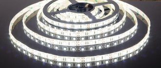
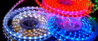
New linear light sources, LED strips, use ultra-bright light-emitting diodes (LEDs) as light-emitting devices. The operating voltage of LEDs is several volts. Therefore, a transformer for a 12 volt LED strip is used for power supply.
Often an inexperienced person has questions about what kind of transformer is needed to power LEDs? How to calculate the power of a transformer? Is it possible to make a transformer with your own hands? How to choose a transformer from those available? Is it possible to do without a transformer? In this material the reader will find answers to these and other questions.
Purpose
Industrially produced LED strips are powered by a constant voltage of 12 or 24 volts. Strips rated for 12 V are more often used. Therefore, LED strips cannot be powered directly from a 220 V lighting network. To power them, a step-down transformer is required. More precisely, a 12 V power supply. Since LEDs operate on direct current, the power supply, in addition to a step-down transformer, must contain a rectifier and an anti-aliasing filter.
A rectifier connected to the secondary winding of the transformer serves to convert alternating current into direct current. Diodes assembled in a bridge or half-bridge circuit can be used as a rectifier. The operating current of the diodes must exceed the total operating current of the LED strips connected to the power supply.
The output of the rectifier produces a pulsating voltage. The ripple frequency is equal to twice the mains frequency. To eliminate ripples, smoothing filters are used. In practice, to smooth out ripples, electrolytic capacitors with an operating voltage exceeding the output voltage of the transformer are used. The capacitance value of the capacitors depends on the power of the power supply.
Supply voltage ripple directly affects the light flux ripple factor. The lower the light pulsation coefficient, the more comfortable a person feels when in a room with artificial lighting. If the capacitance of the anti-aliasing filter capacitors is chosen correctly, then the pulsation coefficient of the light flux will not exceed a few percent, which is considered a good indicator.
Having a little knowledge in electrical engineering, you can independently make a power supply for LED from a transformer, diodes and capacitors.
Purpose and classification of transformers
The main purpose of a power supply or transformer is implied in its name - converting the mains voltage from 220 volts to 12V. In practice, four main types of blocks are used:
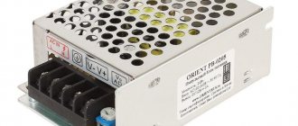
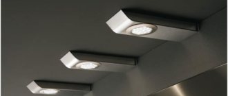
In plastic cases. Their main advantage is naturally their compactness, presentable appearance and light weight. We can also mention tightness, but at the same time it leads to the main disadvantage of such systems - the complexity of heat transfer. This directly limits the power of the lighting fixture that can be connected. In the picture on the right you can see a 12 volt block,
In aluminum cases. Compared to the previous type, it is more expensive and weighty. But the sealed metal case, on the contrary, does not complicate, but promotes heat exchange. Such devices are more durable, reliable and durable. They are resistant to the negative influence of the external environment, therefore they are used in external advertising products,
Open type. The most widespread and cheapest, due to its simplicity, version of the transformer. Larger than previous models, it also has a less presentable appearance. They also have a fairly low level of dust and moisture protection (if they are provided for by the design at all),
Compact type. A small, simple device in design and operation, which implements the principle of non-stationary installation. Their power does not exceed 60 W. Used to power belts of standard length (no more than 5 m). This unit is very easy to connect, which is its main advantage.
Kinds
To power LED strips, two types of power supplies are used containing:
- conventional step-down transformer;
- pulse voltage converter (electronic transformer).
As a step-down transformer, depending on the type of LED strip, any 12V or 24V transformer of appropriate power with a rectifier and smoothing capacitors is suitable. This can be a transformer wound on an W-shaped or toroidal core.
Well-suited commercially available toroidal transformers are designed to power low-voltage lamps for spotlights. They are compact in size and have sufficient power to connect an LED strip.
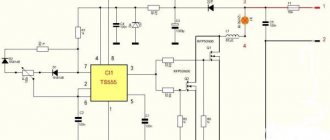
Power supplies for LED strips produced by industry are usually made in the form of pulse voltage converters (inverters). In them, the mains voltage is sequentially rectified, converted into high-frequency voltage (up to 40 kHz), transformed by a pulse transformer, rectified and smoothed. The operation of power supplies for computers, televisions and many other electronic devices is based on the same principle.
Due to the relatively high conversion frequency, switching power supplies significantly outperform transformer power supplies in terms of weight and size. For the same reason they do not hum, they have a low pulsation coefficient. The great advantage of switching power supplies is that they provide stable voltage over a wide range of input mains voltage.
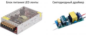
The difference between a power supply and a driver
A driver is a device similar in its tasks to a power supply, only at the output it stabilizes not the voltage, but the current at the same level. Since current is required to power a strip of LEDs, they have a so-called current-voltage characteristic of voltage drop.
Therefore, if LED lamps are connected from a pulse unit, and not from a driver, then their further operating mode may be unpredictable. They will shine, but with what mode and for how long is unknown. For each driver, a certain number of LEDs should be selected. When one fails, the driver will direct its current to the remaining ones. This may cause overheating and burnout.
Using a computer's power supply as a driver
Instead of a power supply for a diode strip from a store, you can take a unit from a personal computer. You just need to compare its characteristics with the parameters of the LED strip: the power and constant voltage of 12V correspond, then you can safely connect it.
Everything will work, but for high-quality and durable lighting it is better to choose special varieties.
Calculation
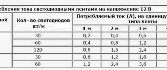
Regardless of what type of transformer is intended to be used to power the LED strip, you first need to determine the power of the connected load. To do this, you need to know how much power one linear meter of tape consumes and how many meters will be spent to organize lighting. Such information can be obtained from the technical documentation for this type of LED or obtained from the seller.
Unfortunately, often the stated technical characteristics do not correspond to the real ones. If in doubt, it is better to make simple measurements to find out the real numbers. To do this, the LED strip must be connected to a suitable voltage source and the current consumed must be measured. Such a source can be a laboratory power supply, a car battery charger, or the 12 or 24 volt battery itself.
Current measurements are carried out by connecting a DC ammeter into the open circuit or using a DC current clamp. You can calculate the power consumed by the connected tape using the formula:
P=U*I
Where P is power consumption; U – voltage; I – current consumption.
Dividing the obtained value by the length of the connected strip, we get the power of one linear meter of LED strip. Knowing the “footage” of the tape that is supposed to be installed, it is easy to calculate the power consumption. It is better to choose the power of the power supply with a margin of several tens of percent. This will avoid excessive heating and increase the reliability of the lighting system.
DIY monitor LED backlight
Time passes unnoticed and seemingly recently purchased equipment is already breaking down. So, having worked their 10,000 hours, the lamps of my monitor (AOC 2216Sa) gave up their life. At first, the backlight did not turn on the first time (after turning on the monitor, the backlight turned off after a few seconds), which was solved by turning the monitor on/off again; over time, the monitor had to be turned off/off 3 times, then 5, then 10, and at some point it could not turn on the backlight, regardless of the number of attempts to turn it on. The lamps brought to the light of day turned out to have blackened edges and were legally thrown into scrap. An attempt to install replacement lamps (new lamps of the appropriate size were purchased) was unsuccessful (the monitor was able to turn on the backlight several times, but quickly went into on-off mode again) and finding out the reasons for what the problem could be in the electronics of the monitor led me to the idea that it will be easier to assemble your own monitor backlight using LEDs than to repair the existing inverter circuit for CCFL lamps, especially since there have already been articles on the Internet showing the fundamental possibility of such a replacement.
Disassembling the monitor
A lot of articles have already been written on the topic of disassembling the monitor, all monitors are very similar to each other, so in brief: 1. Unscrew the mount that comes with the monitor and the only bolt at the bottom that holds the back wall of the case
2. At the bottom of the case there are two grooves between the front and back of the case, insert a flat-head screwdriver into one of them and begin to remove the cover from the latches along the entire perimeter of the monitor (simply turning the screwdriver carefully around its axis and thereby lifting the case cover). There is no need to exert excessive effort, but it is difficult to remove the case from the latches only the first time (during the repair I opened it many times, so the latches became much easier to remove over time). 3. We have a view of the installation of the internal metal frame in the front of the case:
We take out the board with the buttons from the latches, take out (in my case) the speaker connector and, bending the two latches at the bottom, take out the inner metal case. 4. On the left you can see 4 wires connecting the backlight lamps. We take them out by squeezing them slightly, because... To prevent it from falling out, the connector is made in the form of a small clothespin. We also remove the wide cable going to the matrix (at the top of the monitor), squeezing its connector on the sides (since the connector has side latches, although this is not obvious at first glance at the connector):
5. Now you need to disassemble the “sandwich” containing the matrix itself and the backlight:
There are latches along the perimeter that can be opened by lightly prying with the same flat screwdriver. First, the metal frame holding the matrix is removed, after which you can unscrew three small bolts (a regular Phillips screwdriver will not work due to their miniature size, you will need a particularly small one) holding the matrix control board and the matrix can be removed (it is best to place the monitor on a hard surface, such as a table covered with the fabric matrix facing down, unscrewing the control board, put it on the table unfolded through the end of the monitor and simply lift the case with the backlight, lifting it vertically up, and the matrix will remain lying on the table. You can cover it with something so that it does not gather dust, and assemble it exactly the opposite way order - i.e. cover the matrix lying on the table with the assembled case with backlight, wrap the cable through the end to the control board and, screwing the control board, carefully lift the assembled unit). The matrix is obtained separately:
And the backlit block separately:
The backlit block is disassembled in the same way, only instead of a metal frame, the backlight is held by a plastic frame, which simultaneously positions the plexiglass used to diffuse the backlight light. Most of the latches are located on the sides and are similar to those that held the metal frame of the matrix (they open by prying with a flat-head screwdriver), but on the sides there are several latches that open “inward” (you need to press on them with a screwdriver so that the latches go inside the case). At first I remembered the position of all the parts to be removed, but then it turned out that it would not be possible to assemble them “wrongly” and even if the parts look absolutely symmetrical, the distances between the latches on different sides of the metal frame and the fixing protrusions on the sides of the plastic frame holding the backlight will not allow them to be assembled “wrongly” " That's all - we disassembled the monitor.
LED strip lighting
At first, it was decided to make the backlight from an LED strip with white LEDs 3528 - 120 LEDs per meter. The first thing that turned out to be is that the width of the tape is 9 mm, and the width of the backlight lamps (and the seat for the tape) is 7 mm (in fact, there are backlight lamps of two standards - 9 mm and 7 mm, but in my case they were 7 mm). Therefore, after examining the tape, it was decided to cut 1 mm from each edge of the tape, because this did not affect the conductive paths on the front part of the tape (and on the back, along the entire tape, there are two wide power cores, which will not lose their properties due to a decrease of 1 mm over a backlight length of 475 mm, since the current will be small). No sooner said than done:
In the same way, the LED strip is carefully trimmed along its entire length (the photo shows an example of what happened before and what happened after trimming). We will need two strips of 475 mm tape (19 segments of 3 LEDs per strip). I wanted the monitor backlight to work the same way as the standard one (i.e. it was turned on and off by the monitor controller), but I wanted to adjust the brightness “manually”, as on old CRT monitors, because This is a frequently used function, and I got tired of navigating through on-screen menus pressing several keys every time (on my monitor, the right-left keys do not adjust the monitor modes, but the volume of the built-in speakers, so the modes had to be changed through the menu every time). To do this, I found a manual for my monitor online (for anyone who needs it, it’s attached at the end of the article) and on the page with the Power Board, according to the diagram, +12V, On, Dim and GND were found that are of interest to us.
On - signal from the control board to turn on the backlight (+5V) Dim - PWM control of the backlight brightness +12V turned out to be far from 12, but somewhere around 16V without a backlight load and somewhere around 13.67V with a load It was also decided that there would be no PWM adjustments do not adjust the brightness of the backlight, but power the backlight with direct current (at the same time, the issue is resolved that on some monitors the PWM backlight operates at a not very high frequency and for some this makes the eyes a little more tired). In my monitor, the “native” PWM frequency was 240 Hz. Further on the board we found contacts to which the On signal is supplied (marked in red) and +12V to the inverter unit (the jumper that must be removed to de-energize the inverter unit is marked in green). (photo can be enlarged to see notes):
The LM2941 linear regulator was used as the basis for the control circuit, mainly because at a current of up to 1A it had a separate On/Off control pin, which was supposed to be used to control the backlight on/off with the On signal from the monitor control board. True, in LM2941 this signal is inverted (that is, there is voltage at the output when the On/Off input is zero potential), so we had to assemble an inverter on one transistor to match the direct On signal from the control board and the inverted input of LM2941. The scheme does not contain any other excesses:
The output voltage for LM2941 is calculated using the formula: Vout = Vref * (R1+R2)/R1
where Vref = 1.275V, R1 in the formula corresponds to R1 in the circuit, and R2 in the formula corresponds to a pair of resistors RV1+RV2 in the circuit (two resistors are introduced for smoother brightness adjustment and reducing the range of voltages regulated by variable resistor RV1). I took 1kOhm as R1, and the selection of R2 is carried out according to the formula:
R2=R1*(Vout/Vref-1)
The maximum voltage we need for the tape is 13V (I took a little more than the nominal 12V so as not to lose brightness, and the tape will survive such a slight overvoltage). Those. maximum value R2 = 1000*(13/1.275-1) = 9.91 kOhm. The minimum voltage at which the tape still glows at least somehow is about 7 volts, i.e. minimum value R2 = 1000*(7/1.275-1) = 4.49 kOhm. Our R2 consists of a variable resistor RV1 and a multi-turn trimming resistor RV2. The resistance of RV1 is 9.91 kOhm - 4.49 kOhm = 5.42 kOhm (we select the closest value of RV1 - 5.1 kOhm), and RV2 is set to approximately 9.91-5.1 = 4.81 kOhm (in fact, it is best to first assemble the circuit, set the maximum resistance of RV1 and measure the voltage at At the output of LM2941, set the resistance RV2 so that the output has the required maximum voltage (in our case, about 13V).
Installation of LED strip
Since after cutting the tape by 1 mm, the power conductors were exposed at the ends of the tape, I pasted electrical tape (unfortunately, not blue but black) onto the body in the place where the tape would be glued. The tape is glued on top (it is good to warm the surface with a hairdryer, because the tape sticks much better to a warm surface):
Next, the back film, plexiglass and light filters that lay on top of the plexiglass are mounted. Along the edges I supported the tape with pieces of eraser (so that the edges on the tape did not come off):
After that, the backlight unit is assembled in the reverse order, the matrix is installed in place, and the backlight wires are brought out. The circuit was assembled on a breadboard (due to simplicity, I decided not to wire the board), and was fastened with bolts through holes in the back wall of the metal monitor case:
Power and control signal On were supplied from the power supply board:
The estimated power allocated to the LM2941 is calculated using the formula:
Pd = (Vin-Vout)*Iout +Vin*Ignd
For my case, it is Pd = (13.6-13)*0.7 +13.6*0.006 = 0.5 Watt, so it was decided to make do with the smallest radiator for the LM2941 (placed through a dielectric pad since it is not isolated from the ground in the LM2941). The final assembly showed that the design was fully functional:
Among the advantages:
- Uses standard LED strip
- Simple control board
Disadvantages:
- Insufficient backlight brightness in bright daylight (the monitor is placed in front of a window)
- The LEDs in the strip are not spaced closely enough, so small cones of light from each individual LED are visible near the top and bottom edges of the monitor
- The white balance is a little off and goes slightly greenish (most likely this can be solved by adjusting the white balance of either the monitor itself or the video card)
Quite a good, simple and budget option for repairing the backlight. It’s quite comfortable to watch movies or use the monitor as a kitchen TV, but it’s probably not suitable for everyday work.
Adjusting brightness using PWM
For those Habro residents who, unlike me, do not remember with nostalgia the analogue brightness and contrast control knobs on old CRT monitors, you can make control from the standard PWM generated by the monitor control board without moving any additional controls outside (without drilling the monitor body). To do this, it is enough to assemble an AND-NOT circuit on two transistors at the On/Off input of the regulator and remove the brightness control at the output (set the output voltage to constant 12-13V). Modified scheme:
The resistance of the trimming resistor RV2 for a voltage of 13V should be around 9.9 kOhm (but it is better to set it exactly when the regulator is on)
More dense LED backlight
To solve the problem of insufficient brightness (and at the same time uniformity) of the backlight, it was decided to install more LEDs and more often. Since it turned out that buying LEDs individually is more expensive than buying 1.5 meters of strip and desoldering them from there, a more economical option was chosen (desoldering LEDs from the strip). The 3528 LEDs themselves are placed on 4 strips 6 mm wide and 238 mm long, 3 LEDs in series in 15 parallel assemblies on each of the 4 strips (the layout of the boards for the LEDs is included). After soldering the LEDs and wires, the following is obtained:
The strips are laid in twos at the top and bottom with wires to the edge of the monitor at the joint in class=”aligncenter” width=”1600″ height=”1200″|fcw3qayjh5a| src=”https://habrastorage.org/getpro/habr/post_images/3bd/195/f7c/3bd195f7c18e070bc0ed930d0be5044e.jpg” class=”aligncenter” width=”1600″ height=”1200″[/img] Nominal voltage on LEDs 3.5V (range from 3.2 to 3.8 V), so an assembly of 3 series LEDs should be powered by a voltage of about 10.5V. So the controller parameters need to be recalculated:
The maximum voltage we need for the tape is 10.5V. Those. maximum value R2 = 1000*(10.5/1.275-1) = 7.23 kOhm. The minimum voltage at which the LED assembly still glows at least somehow is about 4.5 volts, i.e. minimum value R2 = 1000*(4.5/1.275-1) = 2.53 kOhm. Our R2 consists of a variable resistor RV1 and a multi-turn trimming resistor RV2. The resistance of RV1 is 7.23 kOhm - 2.53 kOhm = 4.7 kOhm, and RV2 is set to approximately 7.23-4.7 = 2.53 kOhm and adjusted in the assembled circuit to obtain 10.5V at the output of LM2941 at the maximum resistance of RV1. One and a half times more LEDs consume 1.2A of current (nominally), so the power dissipation on the LM2941 will be equal to Pd = (13.6-10.5)*1.2 +13.6*0.006 = 3.8 Watt, which already requires a more solid heatsink for heat removal:
We collect, connect, we get much better:
Advantages:
- Quite high brightness (possibly comparable, and perhaps even superior to the brightness of the old CCTL backlight)
- The absence of light cones at the edges of the monitor from individual LEDs (LEDs are located quite often and the backlight is uniform)
- Still a simple and cheap control board
Flaws:
- The issue with the white balance, which goes into greenish tones, has not been resolved
- LM2941, although with a large heatsink, gets hot and heats everything inside the case
Control board based on step-down regulator
To eliminate the heating problem, it was decided to assemble a brightness controller based on a Step-down voltage regulator (in my case, an LM2576 with a current of up to 3A was chosen). It also has an inverted On/Off control input, so for matching there is the same inverter on one transistor:
Coil L1 affects the efficiency of the converter and should be 100-220 µH for a load current of about 1.2-3A.
The output voltage is calculated using the formula: Vout=Vref*(1+R2/R1)
where Vref = 1.23V. For a given R1, you can obtain R2 using the formula:
R2=R1*(Vout/Vref-1)
In calculations, R1 is equivalent to R4 in the circuit, and R2 is equivalent to RV1+RV2 in the circuit. In our case, to adjust the voltage in the range from 7.25V to 10.5V, we take R4 = 1.8 kOhm, variable resistor RV1 = 4.7 kOhm and trimming resistor RV2 at 10 kOhm with an initial approximation of 8.8 kOhm (after assembling the circuit, it is best to set its exact value by measuring the voltage at the output of LM2576 at maximum resistance RV1). I decided to make a board for this regulator (the dimensions did not matter, since there is enough space in the monitor to mount even a large board):
Control board assembly:
After installation in the monitor:
Everyone is here:
After assembly everything seems to work:
Final option:
Advantages:
- Sufficient brightness
- Step-down regulator does not heat up and does not warm up the monitor
- There is no PWM, which means nothing blinks at any frequency
- Analogue (manual) brightness control
- No restrictions on minimum brightness (for those who like to work at night)
Flaws:
- The white balance is slightly shifted towards green tones (but not much)
- At low brightness (very low), unevenness in the glow of LEDs of different assemblies is visible due to the spread of parameters
Improvement options:
- White balance is adjustable both in the monitor settings and in the settings of almost any video card
- You can try installing other LEDs that will not noticeably disrupt the white balance
- To eliminate the uneven glow of LEDs at low brightness, you can use: a) PWM (adjust the brightness using PWM by always supplying the rated voltage) or b) connect all the LEDs in series and power them with an adjustable current source (if you connect all 180 LEDs in series, you will need 630V and 20mA), then the same current should pass through all the LEDs, and each one will have its own voltage drop; the brightness is regulated by changing the current and not the voltage.
- If you want to make a PWM-based circuit for LM2576, you can use a NAND circuit at the On/Off input of this Step-down regulator (similar to the above circuit for LM2941), but it is better to put a dimmer in the gap of the negative wire of the LEDs via a logic-level mosfet
You can download from this link:
- AOC2216Sa Service Manual
- LM2941 and LM2576 datasheets
- Regulator circuits for LM2941 in Proteus 7 and PDF format
- Board layout for LEDs in Sprint Layout 5.0 format
- Diagram and layout of the regulator board on LM2576 in Proteus 7 and PDF format
Choice
We have already discussed how to choose the power of a transformer. However, in some cases it is more advisable to use several low-power transformers instead of one powerful device. This can be done, for example, based on considerations of the location of individual sections of the LED strip. Or, based on the dimensions, when the question arises of where to hide a high-power transformer.
We have already dwelled on the advantages of “electronic” transformers. However, the electronic components used in them are more demanding for effective cooling. Often, to cool the electronics of such power supplies, fans are installed inside the case.
The choice of power supplies should be approached with some caution, since over time the fans sometimes begin to make quite loud noise and measures have to be taken to eliminate the noise. It is better to opt for converters in which the housing serves as a radiator for heat removal. Such cases have a developed ribbed surface.
When choosing a transformer, you need to consider the location of its installation. If the lighting is intended to be installed outdoors or in damp rooms, it is necessary to select a device with the appropriate protection class.
Additionally, you can watch an interesting video about choosing a transformer. The author gives useful comments that will definitely come in handy when choosing a transformer.
Which class of dust and moisture protection to choose?
We have determined the main parameters of the power supply - voltage and power - all that remains is to choose the type of case that would meet the operating conditions of the device. If the power supply will operate indoors, then protection from moisture is not so important, but lighting, for example, the facade of a building, of course, will require the purchase of a sealed device.
But there are many different types of cases, sometimes the most bizarre ones, so it is quite difficult to assess how reliably a particular power supply is protected from environmental influences by its appearance. How to choose a device for the conditions in which it will be used? This is simple if you pay attention to the marking, consisting of the letters IP and two numbers. The first of them indicates the class of protection against solids and particles, the second - against moisture. Now let's take a look at the table below.
Table of environmental protection classes according to DIN EN 60529
| 1st digit (protection against solids and particles) | 2nd digit (moisture protection) | ||
| 0 | No protection | 0 | No protection |
| 1 | Protection against penetration of particles larger than 50 mm | 1 | Protection against vertically falling drops |
| 2 | //-//-//-// more than 12 mm and length more than 80 mm | 2 | Protection against drops falling at an angle of 15° from vertical |
| 3 | //-//-//-// more than 2.5 mm | 3 | Protection against drops falling at an angle of 60° from the vertical (rain) |
| 4 | //-//-//-// more than 1 mm | 4 | Protects against splashes from any angle |
| 5 | Protection against ingress of dust in quantities that could interfere with the operation of the device | 5 | Protection against water jets from any direction |
| 6 | Complete protection against dust ingress | 6 | Protection against strong water jets from any direction |
| 7 | Protection against short-term immersion in water up to a depth of 1 m | ||
| 8 | Protection when immersed in water up to a depth of 1 m for a period of no more than 30 minutes | ||
| 9 | Protection against high temperature water jets | ||
If our power supply will work outdoors or in the bathroom, then, according to the table, we will have to choose a device with a degree of protection of at least IP65, and preferably IP67. Installing in a dusty room? IP54 will do. A dry, clean room, and even sewn under a false panel? Let's choose IP20. Well, if the power supply is built into some other device, then protection is not important at all.
Expert opinion
Alexey Bartosh
Specialist in repair and maintenance of electrical equipment and industrial electronics.
Ask a Question
Important! If we are going to use a power supply in conjunction with a dimmer, then we choose a device in a sealed case, since most open ones (class IP20) begin to “squeak” noticeably and unpleasantly when the brightness of the tape changes.
Connecting an LED strip to a transformer
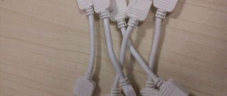
Connecting the LED strip to the power supply is not particularly difficult. When connecting, the main thing is not to confuse the polarity and connect plus to plus, and minus to minus. On the LED strip and on power supplies, the poles are usually marked. Often, special connectors are used to connect LED strips to factory power supplies. They have special protrusions - “keys” and, therefore, it is impossible to make a mistake with the connection.
To connect power supplies to the network, you must use a double-insulated cable. The cross-section of the cable cores must be at least 1.5 mm2. To connect low voltage, depending on the load power, a wire or cable with a core cross-section of 0.75 mm2 or more is suitable. Such a small cross-section is explained by the fact that LEDs consume 8 to 10 times less electricity than incandescent lamps. Cables must be connected to transformers using standard connectors or using screw or spring clamps.
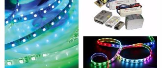
Connecting “three-color” (RGB) LED strips has some features. RGB strips usually work with special controllers. Therefore, when connecting three-color LED strips, it is not the strip itself that is connected to the power supply, but the controller, which in turn powers the LEDs. There is also a limitation on the length of the tape connected to the controller. Therefore, special amplifiers are used to extend the chain of LED strips. These amplifiers must also receive power from the power supply.
A few words should also be said about electromagnetic compatibility. Switching power supplies for LED strips can cause interference. Therefore, it is worth considering using network filters. To effectively suppress interference, they must be located in close proximity to the power supply.
Reasons for LED strip failure
Tapes or their fragments often burn out without producing the declared resource. The reasons for this may be:
- Non-branded LEDs, which fail when heated.
- Incorrect installation causes overheating of the LEDs and damage to the tracks. Gluing the tape tightly causes the entire tape to heat up more. The tape should not be bent more than 5 cm.
- Excess supply voltage. It is better to reduce it from 12 to 11.5 - 11.7 V using a construction resistor installed next to the wire terminals.
How to make your own transformer
You can make the simplest transformer for an LED strip yourself. First you need to calculate the power and current consumed by the LED strip. Based on the power consumption, choose a 12 V step-down transformer. You will also need four rectifier diodes or an integrated diode bridge. The maximum permissible current of the diodes must exceed the current consumed by the LED strip. To smooth out the ripples of the rectified voltage, electrolytic capacitors are required. The operating voltage of the capacitors of a 12-volt power supply must be at least 25V. The total capacity can be calculated based on 3000 microfarads per load ampere. All parts must be soldered according to the diagram below.
The resulting structure must be placed in a suitable housing.
Considering all of the above, we can say that the use of a high-quality transformer is a necessary condition for long-term and reliable operation of the LED strip. At the same time, it must have a power reserve, provide a low ripple factor, not be afraid of mains voltage surges and have a protection class corresponding to the operating conditions.
Connecting Wires and Terminals
You can choose the right block, purchase a high-quality tape, but when connecting, use a thin cable and not achieve the desired cross-section. To correctly select the cross-section and power wires, you can use two methods.
Selection by belt load
Since it is not always possible to use a table of correspondence between current and wire cross-section, you can use the universal dependence. It has been established that every 10A of connected load will require a copper wire of 1 sq. mm.
To determine the amount of current that the backlight consumes, it is necessary to divide the total power by the resistance value. Next, divide the calculated current value by 10A, according to the formula, to obtain the required wire cross-section used for installation.
Selection by block power
It is not the power of the belt that is used, but the power of the block. It is required that the condition be met: the device must withstand 1.35 of the rated current of the power source.
In addition to normal operation of the tape, short circuits may occur. The protection is triggered at overloads of 1.05 - 1.35.