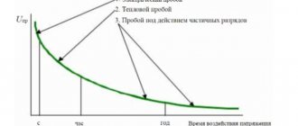
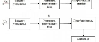
Systematic checks of the state and functioning of touch voltage are established by the requirements of PTEEP, PUE, GOST and POT. They can prevent failure of electrical installations and ensure electrical safety of their operation, including hand tools and equipment. These include devices, machines, machine tools, household appliances and much more.
The main purpose of measuring touch voltage is to assess its condition and compliance with regulatory documents.
Touch voltage is the amount of voltage that occurs during damage to conductive elements and is called breakdown on open parts of electrical equipment. Contact with them is possible for people who touch power tools, household appliances, machines or other electrical equipment, the elements of which are in contact with wires that have damaged insulation.
Therefore, measuring touch voltage is important to assess the likely hazard from contact with electrical equipment.
The measurement represents the potential difference between the point of contact of the electrical equipment and the position of the person on the ground.
Protection measures
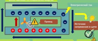
In addition to workwear, there are design considerations. To reduce the stress of step and touch, the potentials are equalized. This is achieved by introducing a grounding conductor into the soil at several points. Usually along the perimeter of a certain shape. It turns out that the potential is equal at all input points, and the touch voltage is highest outside the specified line. There remains a danger inside due to pseudo-random processes, but much lower than with a single circuit.
The shape of the perimeter depends on the conditions available on the ground: a line, if this increases the safety of movement, or a grid, square, hexagon, etc. If we take European standards, the design of the underground grounding circuit is found in the form of a comb. This is done to reduce the spreading current: moving charges fall on a larger perimeter, which naturally reduces the potential difference (according to Ohm’s law for a section of the circuit). A similar idea was used in the above case. The longer the perimeter, the lower the touch voltage.
So, the design of the ground electrode plays a big role in protecting personnel and bystanders from danger. In particular, the territory of the enterprise reveals a cluster of random grounding conductors combined into a single circuit. Including lightning rod circuit. All this is done to reduce the danger in case of an accident.
Let us continue to emphasize: it is leakage cases that are being considered. In other situations, the current through the protective and working neutral conductor is very small
This is achieved both by the serviceability of the insulation and by a uniform load across all phases.
Electrical injuries
They say that birds sit on bare wires and do not fall from the discharge, the resistance of the skin of their legs is high, the current flows mainly through the wire. If a person tries to grab the power line at a similar distance with both hands, the outcome will be disastrous.
Electrical injuries are usually divided into local and general. The first type accounts for a fifth of the total number of accidents in industry, the second – more than half. Other impacts are reduced to ordinary shocks (excitation of body tissues, involuntary muscle contraction), as a rule, without consequences. Local electrical injuries are accompanied by burns, metallization of the skin from molten metal, eye damage and electrical marks (relatively harmless marks on the skin of a varied nature). A strong electric shock can stop the heart and lungs.
The most common local injuries are burns. They account for two thirds of all symptoms. Electricians operating existing installations are at greatest risk. Electric shocks are usually divided into 5 groups:
- Unpleasant sudden loss of orientation, instant convulsion.
- Body reflexes accompanied by sharp pain.
- Loss of consciousness from electric shock without other visible consequences.
- Impaired cardiac activity with simultaneous loss of consciousness. Trouble breathing.
- Clinical death.
As you might guess, even briefly touching exposed parts of electrical equipment leads to unpleasant consequences. Electrical shocks account for five-sixths of the total fatalities reported in workplaces.
Definition of the concept
When a person or animal touches with his body exposed live parts, the body of a device that for some reason is under potential, a cable with damaged insulation, etc., while he himself is standing on the ground, then the potential difference between the point of contact and the ground is called voltage touch.
In other words, this is the voltage under which two exposed conductive parts are not connected to each other.
The conditions for occurrence are as follows - the enclosures of electrical appliances are usually grounded, but damage to the insulation of electrical equipment inside these enclosures causes touch voltage to appear when you put your hand on the metal part of the enclosure and associated metal parts.
Method of measurement
Measurement methods must meet the following basic requirements:
- the measurement error should not exceed 4% (if possible, it is necessary to carry out measurements using the direct method, the result of which is the value of the touch voltage and step when creating a real short circuit, limited in time - MRP-120 device);
— low labor intensity of measurement;
— electrical safety of personnel performing measurements, as well as persons who accidentally come into contact with grounded parts of the electrical installation during measurements.
Touch and step voltage measurement and test procedure
Purpose of measurements
The voltage between two points located at a distance of the average step length is called step voltage. The contact points between conductors and the ground or floor have the greatest potential. Moving away from the surface, the potential decreases. The increase in the cross-section of the conductor is proportional to the full square of the radius; at distances of about 18-25 m it can be conditionally equated to 0. With an increase in the support area, the danger of step voltage increases.
The voltage between points that can be touched at the same time is called touch voltage.
The voltage value depends on several factors:
- diagrams of the circuit being measured;
- neutral and its implementation;
- implementation of insulation of conductive elements;
- capacitance values of conductive elements.
For personnel safety, step and touch voltages must be measured and calculated. Without checking, you cannot protect your equipment during power surges.
Standards and testing methods
In accordance with regulatory documentation, measurements are carried out in rooms where electrical installations are short-circuited to the ground, in rooms with a large extent of metal and conductive installations. In such rooms, if the insulation breaks down, potentials may appear.
Touch voltage measurements are carried out:
- if it is not possible to disconnect the grounding for the duration of measurements;
- with a high risk of ground faults at a short distance from the ground being tested or near equipment connected to this ground;
- if the equipment circuit in contact with the ground does not differ significantly from the dimensions of the ground being tested.
To carry out measurements, special equipment is used, with its help the correct connection of the equipment is checked. The norms of quantities differ in the types and properties of the critical regime:
- single-phase short circuit of live parts to ground in networks up to 1 kV;
- short circuit of installation elements to ground from the highest voltage of the substation 6-10 kV/0.4;
- ground fault in networks with voltage 6-35 kV;
- single-phase short circuit to the body in networks up to 1 kV;
- ground fault from high voltage with deep input at a voltage of 110 kV;
- ground fault in networks with a voltage of 110 kV with deep input;
In each specific case, the voltage value, the maximum duration of exposure, and the response time of the protection elements are calculated.
When making measurements, a set of measures is developed to prevent any accidents, to implement the work plan, as well as to implement the operation process in accordance with electrical safety standards.
Application area
1.1.1. If an emergency mode occurs - a short circuit to the grounded (zeroed) part - voltage appears on the electrical installation body relative to the ground. This emergency mode is maintained during the duration of the protection of the electrical installation from short circuit currents. If a person or animal comes into contact with voltage between two points of the ground fault circuit (frame) - touch voltage - during protection, it can cause electrical injury. To reduce touch voltage to a safe value, electrical potential equalization devices (EPD) are used.
1.1.2. Potential equalization is an independent protective measure when ensuring electrical safety in electrical installations.
1.1.3. This Methodology applies to the measurement of touch and step voltages and establishes the method and means of measurement, the algorithm for preparing and carrying out measurements, processing measurement results, quantitative indicators of accuracy and methods of their expression.
1.1.4. The technique is mandatory for use by electrical laboratory personnel performing tests and measurements during the operation of consumer electrical installations.
1.1.5. The technique provides reliable indicators of measurement accuracy in stationary operation of electrical installations.
Is touch voltage safe?
Let's start with what exactly is dangerous? Tension in itself is not particularly dangerous. Electric current has destructive and dangerous effects. However, the likelihood of receiving an electric shock depends on the voltage. An alternating current voltage of 42 Volts is considered safe; previously it was considered 36 V. It is used for arranging portable lamps and for powering power tools, when working in hard-to-reach places, in garages, basements, wet rooms, as well as in places of temporary work. But touch tension and safe tension for a person are slightly different things.
The effect of electric current on a person is destructive, it can cause fibrillation contraction of the heart and death, therefore the values of permissible voltages and currents are prescribed in regulatory documents. According to the standards described in GOST 12.1.038-82, touch voltage under normal conditions (without accidents) should not be greater than:
- with alternating current with a frequency of 50 Hz – 2 V (current – 0.3 mA);
- with alternating current with a frequency of 400 Hz – 3 V (current – 0.4 mA);
- at direct current – 8 V (current – 1 mA);
These are the maximum permissible values for exposure up to 10 minutes per day. It is worth noting that for people who work at temperatures greater than 25°C and relative humidity greater than 75%, these values are reduced by 3 times.
Since touch voltage is measured between the place of a person’s position on the ground (his contact with a conductive surface) and the place of contact with electrical equipment, it follows that it depends on the location in the room, more precisely relative to the grounding point. The farther you stand at the moment when you touched a dangerous device, on whose body there was potential (from the grounding point), the greater the value of the touch voltage.
A few more definitions are worth noting:
- Spread zone. This area on the ground, beyond which the potential that arises when a ground fault current flows, is equal to zero. Outside the spreading zone, the touch voltage is numerically equal to the potential on the surface you touch.
- Step voltage. This is the voltage between two points on the ground (soil) around the point where the live part is shorted to ground. The idea is that if a high-voltage cable falls near you, you need to move away from it in small incremental steps, without lifting your feet from each other and from the ground, thus reducing the distance between steps. The potential from the ground fault point decreases exponentially. This means that at the point of the ground fault it is equal to the potential of the shorted conductor, and outside the spreading zone it is zero. Then the voltage between these two points is equal to the voltage of the closed cable.
You should have noticed that touch voltage, spread zone and step voltage are all related.
What is touch voltage, its norms, calculation and protective measures
When working with electrical installations in an alternating current circuit, the possibility of feeling its influence cannot be completely excluded. The cause may be accidental contact with live elements or indirect factors. We have already talked about one of them (step voltage) in detail on the pages of our website. This article will discuss another type of indirect effect of electric current on a person, called touch voltage.
What is “touch voltage”?
In electrical safety, this term refers to the potential difference between two points in an electrical circuit that occurs at the moment a person touches them simultaneously.
This situation can arise as a result of a violation of the insulation of current-carrying circuit elements, their short circuit to electrically conductive surfaces, which leads to the formation of dangerous zones of current flow.
Contact with such a surface is called indirect contact with the housing or electrically conductive elements (depending on the electrical installation design).
Rice. 1. Example of indirect touch
In such cases, the degree of exposure to electric current depends on both the resistance of the human body (R) and the magnitude (Upr). Let us assume in this case that R = 800 Ohm, Upr is close to the phase voltage (230 V). Using Ohm's law, it is easy to calculate the amount of current in the resulting electrical circuit: Ipr=Upr/R= 220/800 = 287.5 mA. This value is several times higher than the permissible standards.
In most cases, indirect contact is single-pole, that is, in this case, the threat is posed by phase rather than line voltage, which is 1.73 times higher. But this is little consolation, since electric shock can still be fatal.
The danger of indirect touching lies in the fact that the risk of its occurrence, in most cases, does not depend on human actions, unlike direct touching, which can occur through negligence, as a result of an error or non-compliance with safety regulations.
Measurement methods
The measurements are carried out by a visiting team of a special laboratory that has a license to perform such measurements. Work and non-work places are measured. Measurements are carried out at an ambient temperature of 5-400C and air humidity of 35-80%.
Measuring circuit at the workplace
Attention! The workplace is the area of operation of operational personnel within the framework of the regular work process. A non-working place is an area where there may be people who are not performing official duties related to work in electrical installations.
Before making measurements, the neutral conductor is disconnected from the shield to preliminary measure the resistance of the grounding loop. Next, when assembling the measurement circuit, one output of the device is connected to the protective grounding bus, and the second to the current electrode. Maintaining a distance of more than 25 m from the ground electrode, drive the pin into the ground and install a plate on which a load of 50 kg is placed. This is an imitation of a human leg. The soil under the plate is moistened. The voltmeter V monitors the touch voltage, the resistance R = 1 kOhm is equivalent to the resistance of the human body.
When performing measurements at non-working places, the terminal of the T2 device must be connected to the grounding point of the equipment housing located nearby.
The placement of the current electrode must be done so that the artificial reproduction of the phase voltage ground fault circuit is as accurate as possible.
Another measurement method is a circuit using a voltmeter and an ammeter.
The first tests the touch voltage, the second shows the amount of current flowing through the ground electrode. The power source of the measuring circuit is a transformer with an output voltage of 500 V and a rated power of 100 kVA.
Ammeter and Voltmeter Testing
Taking a measurement
5.1. When performing touch voltage measurements, you must:
— before each measurement it is necessary to check the functionality of the measuring instrument;
— checking the correct connection of the network socket before performing tests and measurements using the MRP-120 meter is not necessary. The meter automatically monitors the correct connection and signals connection errors.
— maintain normal operation of the measuring instrument.
5.2. To measure the touch voltage and tripping current of the RCD, you must:
— connect L
,
N
(the neutral wire may not be connected) and
PE
from electrical equipment in accordance with Fig. 1;
— use the switch to select the measurement function UB,IA;
— select the safe voltage value;
— select the initial phase of the test current;
Ub is measured
, the result is displayed on the main reading field.
If the touch voltage measured at 40% In exceeds the preset safety voltage UL
, the measurement will be interrupted and the
Ub
.
Figure 1 – Scheme for measuring touch with the MRP-120 device.
5.3. To start measuring, press the “start” key. The touch voltage value will appear on the display.
How to calculate touch voltage
Belyavin's textbook on electrical safety gives a good idea of how to correctly assess touch voltage when one point of current passage is the leg and the person is standing on the ground. The case of potential arising from leakage of short circuit current is considered. It is obvious that the ground potential decreases exponentially with increasing distance to the ground electrode. At a distance of 20 meters from the point of immersion in the soil it becomes equal to zero.
Belyavin suggests considering the issue of danger as if a person had his hand on the grounding point. Then the least danger (oddly enough) is when he stands nearby. Although the step tension is maximum, you cannot spread your legs far apart so as not to receive a fatal blow. Indeed, the potential of the conductor differs little from the ground; the section is short-circuited by the ground loop. In this case, you must immediately release the current-carrying structure and carefully goose-step away from the scene of the accident.
Step voltage
The situation looks much worse if a person stands half a meter or a meter from the point of immersion of the protective or working (neutral) neutral conductor into the ground. This is more dangerous than taking a step the same distance. Because the resistance between the hand and the metal is small, and the contours of the legs are connected in parallel, which increases the risk of breakdown (rubber shoes do not help either). But the case looks even worse when a piece of grounding conductor is laid in the air parallel to the ground, but does not come into contact with it at any point except where the neutral conductor enters the ground. In the latter case, the potential difference is the highest. Description of the situation:
- A man stands on the ground 20 meters from the entrance of the ground electrode into the ground. Here the potential created by the spreading current is already equal to zero.
- By accident or oversight, a structure running parallel to the ground on dielectric supports (pipeline, fence) with low electrical resistance (metal) turned out to be connected to the point of entry of the neutral conductor into the ground and is located 20 meters from it.
- A person stands on the ground, grasps the iron with his hand according to point 2. Immediately he finds himself under the phase voltage of the network. 220 V will not be able to pierce the sole of a shoe, if you stand barefoot or accidentally lean your other hand on the ground, the touch voltage will be the maximum of the possible options and extremely dangerous (the characteristics of the current path depending on the damage are given at the end of the Step Voltage review).
So, the damage is least if a person stands at the grounding point
In this case, the step voltage is maximum; you need to move away from the source carefully. At a point at a distance of 20 meters, it is permissible to walk freely, but if you accidentally grab the conductor,
2, dire consequences are expected.
Skeptics will say that in the situation described above, the fact of dividing the voltage between the resistance of the neutral conductor lying above and below the ground is not taken into account. In reality, everything is taken into account. The resistance of iron (especially copper) is much lower than the resistance of the ground electrode (the work function of electrons leaving the surface of the circuit into the soil). The last parameter is directly proportional to the soil resistance, and inversely to the geometric dimensions of the contour.
How to calculate voltage correctly
The manual by K. E. Belyavin describes in detail what this concept is and how to calculate it, for example, when the current passes through a conductor, namely through a person’s leg, which is on the ground. The leakage occurs from a short circuit at a distance of 20 meters. If the source is immersed in the ground, then danger is unlikely.
It also discusses issues when a person picks up a live wire, or simply stands next to it. It is in the second case that the danger is least.
How a broken wire can affect a person from a distance
Important! When there is tension in contact, you cannot spread your legs far apart, otherwise you can receive a fatal blow. In the event of a tragedy, you should leave the scene of the accident in a crouch.
When determining touch voltage, consider 2 schemes for calculating networks with a neutral:
Measurement
Touch voltage is measured with an ammeter and a voltmeter. The potential difference is estimated between objects accessible to touch and an imitation of human soles - a metal square plate with an area of 625 square meters lying on the ground. see. The body resistance is replaced by an equivalent resistor, and a voltmeter is connected in parallel to measure the voltage.
The current source is a transformer adapted for testing, which produces a voltage that could hypothetically occur on metal structures. If the circuit voltage is too high, the resistor value is taken higher, and the current will also need to be measured. Then the circuit resistance is calculated and according to the graph (straight line) the values for the “combat” conditions of a real accident are found.
One of the points of the secondary winding is grounded. If this is not possible due to the conditions, an isolation transformer is installed. And already the point of its secondary winding is grounded. This is necessary (in violation of safety regulations) for the “danger” to reach its maximum.
Preparing measuring instruments for measurement
4.1. In preparation for performing touch and step voltage measurements, you should check:
— availability and completeness of documentation necessary for the operation of measuring instruments and auxiliary devices;
— availability of valid verification marks for measuring instruments.
4.2. Prepare measuring instruments and auxiliary devices for operation in accordance with the instructions given in the operating instructions.
4.3. Correct installation of the measurement circuit in accordance with the technical description on the measuring instrument used.
4.4. If possible, reduce (eliminate) the number of factors causing additional error.
Security measures
There is a requirement when working with touch voltage, it should not exceed 65 V, it is considered safe when touched, but not longer than 3 seconds. The threshold depends on what interval it is in:
- 0.1 sec – 740 V;
- 0.2 sec – 370 V.
Necessary requirements:
- During measurements, use protective clothing;
- Preventive work carried out on metal structures involves equipping with insulating materials;
- In case of long-term current leaks, the contact points of metal structures (stairs, pipes, fences) should border on the ground electrode;
In the case of pipelines, we can say with confidence that they are under cathodic protection and the section isolated from the ground electrode is dangerous. The border is located at the junction of the territory of a building or factory. In the event of an accident, it is recommended to remove the power source.
Electrician - in the process of work, in appropriate protective clothing
Often people are injured from exposure to current or arc. Damage to the body can be general or local. The degree of damage depends on the path of the electric current through the victim’s body. There are 5 stages of electric shock:
- Reduction of muscle work;
- Convulsions;
- Heart failure and difficulty breathing;
- Lack of consciousness;
- Death.
The outcome of electric shock depends on the correctness and timeliness of assistance, as well as the correct calculation of the effects of electricity.
To prevent electric shock to people or animals, insulation of cables, windings of electrical machines and other necessary safety measures should be carried out in a timely manner. If the resistance decreases or a short circuit occurs in the electrical network, it is completely turned off.
Features of the Ground Resistance Meter
The is 10 device operates at temperatures from -15 to +55 0С, the permissible maximum ambient humidity is 90%. The housing design of the device has protection class IP42. This ensures safe use in adverse weather conditions.
A full range of measurements that can be performed using the IS-10 in working order:
- determination of the resistance of components of grounding devices;
- measurement of Rcross connection points and continuity of grounding conductors, during which the soil resistivity is automatically determined;
- work using clamps for continuous measurement of alternating current;
- determination of the distribution of currents as a percentage when assessing individual grounding conductors included in the circuit.
Measurements can be carried out using the 2, 3 or 4 wire method.
Ways to reduce the danger
GOST 12.1.038-82 (2001) dated March 01, 2022 is the main regulatory document that is used to guide when taking the necessary measures. This GOST considers the standards for the maximum possible values of touch voltage.
To ensure electrical safety for people, the following steps apply:
- installation of protective grounding devices;
- zeroing of working equipment;
- installation of potential equalization systems (EPS);
- fencing and installation of protective shields on live equipment;
- use of reduced voltage in work in areas with increased danger and especially dangerous ones;
- providing personnel with collective and individual protection items: insulated power tools and dielectric means;
- use of residual current devices (RCDs) and alarms.
Grounding devices are designed to protect against phase-to-frame short circuits. They are installed to reduce the voltage between the ground and live parts of electrical installations.
Important! All metal parts of installations, engines, switchboards, consoles, metal housings of power tools and other elements accessible to touch that can conduct current are subject to mandatory grounding. To protect against extraneous voltage in places where connection to the ground loop is impossible, grounding is used
Using a separate conductor, the device body is connected to a grounded zero. When a phase hits it through this conductor, the short-circuit protection device is triggered
To protect against extraneous voltage in places where connection to the ground loop is impossible, grounding is used. Using a separate conductor, the device body is connected to a grounded zero. When a phase hits it through this conductor, the short-circuit protection device is triggered.
To reduce the risk of electric shock to people, industrial and domestic premises are equipped with potential equalization systems (PES). They are basic (OSUP) and additional (DOSUP). The main system is independent and provides potential equalization on accessible metal surfaces of the equipment. DOSUP takes additional measures to reduce the level of potential difference in particular cases.
The implementation of protective fences and the installation of shields protect people from accidental contact with live parts. As an additional measure, warning posters are posted on the fences.
In places with increased danger and particularly dangerous work can only be done with power tools whose supply voltage is not higher than 42 V. For this, step-down transformers are used.
Information. Rooms with increased danger include those where there are: a chemically aggressive environment, high humidity (more than 70%), elevated temperature (above 500C), accessible contact with metal parts or concrete floors.
Collective and personal protective equipment (PPE) includes: dielectric mats and stands, boots, galoshes, gloves and tools with insulating handles. The use of such protective kits reduces the risk of touch voltage.
RCD - residual current devices installed in the apartment allow you to control the occurrence of current leaks and dangerous voltage in places with increased danger (kitchen, bathroom). When dangerous quantities appear, the device turns off the power supply until the cause of their occurrence is eliminated.
A way to reduce the risk of electrocutionGROUND IC - 10
Manual
This instruction manual (OM) is intended to familiarize you with the design and operating principle of the IS-10 ground resistance meter (hereinafter referred to as the device) and contains information necessary for its proper operation, safety measures and verification methods.
The device corresponds to group 4 according to GOST 22261. Operating temperatures range from minus 15 to plus 55 ºС with an upper relative humidity value of 90% at a temperature of plus 30 ºС. Normal conditions according to clause 4.3.1 of GOST 22261 (permissible temperature deviation 5 ºС).
The device is housed in an IP42 housing in accordance with GOST 14254.
In terms of electrical safety requirements, the device complies with GOST R 51350.
Single ground
This is the simplest type of equipment grounding, in which there is no need to construct a special circuit. Nevertheless, it is a very effective protective component that allows the protective shutdown to operate and “bypass” a person who has come under voltage.
Single protective earthing includes:
- grounding electrode 2500 mm long - angle steel 50*50*0.5 mm or pipe with a diameter of at least 4 mm;
- grounding conductor - rolled steel wire with a diameter of at least 0.8 mm outdoors and 0.6 indoors or a steel strip 25 mm wide and 0.5 mm thick;
- The connection point for the grounding conductor is a bolt for connection on the electrical installation body.
As a grounding conductor indoors, it is permissible to use a flexible stranded copper wire of yellow-green color, with a cross-section of at least 2.5 mm. All connections are made using electric welding. The seams are at least 10-15 mm long. Welding areas and metal grounding parts (except for the electrode driven into the ground) are painted with black paint to protect against corrosion.
Important! The minimum grounding resistance for a 220 V network should be no more than 8 Ohms, for a three-phase 380 V line the minimum value of R ≤ 4 Ohms. The ground electrode is driven or buried in the ground so that its upper part is 0.4-0.5 m below ground level
The ground electrode is driven or buried into the ground so that its upper part is 0.4-0.5 m below ground level.
2.4. Measurement of charger resistance of substations and power lines
2.4.1. Measuring the resistance of substation chargers
Resistance measurement is carried out without disconnecting lightning protection cables, outgoing cable sheaths and other natural grounding conductors. Measurements should be carried out during periods of greatest drying of the soil. When carrying out measurements under conditions different from those specified, it is necessary to apply the seasonal coefficient Kc (see Appendix 3). The resistance of the RGB is determined by the formula
RZU = Ks RZU meas(3)
where RZU meas is the resistance of the memory obtained during measurements.
The resistance of the charger is measured using the ammeter-voltmeter method using one of the following devices: MS-08, M-416, F 4103, EKZ-01, PINP, EKO-200, ANCH-3, KDZ-1, ONP-1 (see. Annex 1). The schematic diagram of measurements is shown in Fig. 2. Current and potential electrodes should be located on the same line in an area free from power lines and underground utilities. The distances from the substation to the current and potential electrodes are selected depending on the size of the charger and the characteristic features of the area around the substation.
Rice. 2. Schematic diagram of charger resistance measurements: charger - grounding device; P—potential electrode; T-current electrode
If the substation ground electrode is small in size, and there is a large area around it, free from power lines and underground communications, then the distances to the electrodes (current and potential) are selected as follows:
r
fl ≥ 5D;
r
ep = 0.5
r
fl.
Here D is the largest linear dimension of the charger, characteristic of a given type of ground electrode (for a polygon-shaped ground electrode, the diagonal of the charger; for a deep ground electrode, the length of the deep electrode; for a radial ground electrode, the length of the beam).
If the ground electrode is large, but there is no large area around it free from power lines and underground communications, the current electrode should be placed at a distance r
floor ≥ 3D.
The potential electrode is placed sequentially at a distance r
ep equal to 0.1
r
fl;
0.2 r
fl;
0.3 r
fl;
0.4 r
floor;
0.5 r
fl;
0.6 r
floor;
0.7 r
fl;
0.8 r
floor;
0.9 r
fl, and the resistance values are measured.
Next, a curve is constructed depending on the resistance value on the distance r
ep.
If the curve increases monotonically and has a horizontal section in the middle part (as shown in Fig. 3), the value at r
ep = 0.5
r
fl is taken as the true resistance value. If the curve is non-monotonic, which is a consequence of the influence of various communications (underground and above-ground), the measurements are repeated with the electrodes located in a different direction from the charger.
Rice. 3. Dependence of the measured resistance on the distance of the potential electrode to the current one: a - with a sufficient distance of the current electrode; b - with insufficient removal of the current electrode; 1 - curve at r
fl = 3D;
2 - curve at r
fl = 2D
If the resistance curve increases smoothly, but does not have a horizontal section (the difference in resistance measured at r
ep = 0.4
r
fl and
r
ep = 0.6
r
fl, exceeds by more than 10% the value measured at
r
ep = 0.5
r
fl) and there is no possibility of moving the current electrode to a greater distance, the following output is possible.
Two series of measurements are carried out at r
fl = 2D and
r
fl = 3D. The curves are plotted on one graph. The intersection point of the curves is taken as the true value of the grounding resistance.
When using M-416, EKZ-01, EKO-200, Anch-3 devices, the curves may not intersect. In this case, it is recommended to use MS-08, F 4103, PINP devices.
mm are used as auxiliary electrodes
.
The rods must be free of paint and, at the point where the connecting conductors are connected, free of rust. The rods are driven or screwed into the ground to a depth of 1.0 - 1.5 m
.
If necessary, the current electrode is made of several parallel-connected electrodes placed around a circle, with a distance between them of 1.0 - 1.5 m
. When choosing a current electrode, it is necessary to check that the resistance of the current circuit corresponds to the technical data of the device with which it is proposed to make measurements. The permissible resistance of the current circuit (with the electrode) has different values for different devices and also depends on the selected range for measuring ground resistance. For the F 4103 device, for example, the permissible resistance of the current circuit, depending on the selected measurement range, varies from 1 to 6 kOhm
.
To check the resistance of the current circuit, it is necessary at the beginning of all measurements to combine the terminals T1 and P1 of the device, connect them to the current electrode and measure the resistance of the current circuit.
When operating electrical installations, it may be necessary to determine the resistance of an artificial ground electrode or the communication resistance of equipment using the memory. Such measurements can be carried out using, for example, the KDZ-1 measuring complex (Appendix 4).
2.4.2. Measuring the resistance of grounding conductors of overhead line supports
The method for measuring the resistance of grounding conductors of overhead line supports without a lightning protection cable differs practically little from measuring the resistance of grounding conductors of a substation.
Since chargers with large dimensions in plan are rarely used on overhead line supports, in most cases, satisfactory results can be obtained by arranging the electrodes according to a two-beam scheme with a distance between the electrodes satisfying the relations:
r
ep =
r
fl = 1.5D;
r
tp = D,
where r
tp is the distance between the current and potential electrodes.
Distance r
ep must be measured from the edge of the charger and in all cases must be at least 30
m
from the support body.
If it is impossible or impractical to disconnect the lightning protection cable from the support body, measuring the resistance of the support grounding conductor can be performed:
using current clamps;
SibNIIE method;
pulse method MPEI - ELNAP.
The measuring method using a current clamp is to measure the total current flowing through all grounding slopes, legs or supports, and the potential of the grounding slope relative to an auxiliary electrode placed in the zero potential zone. Grounding resistance is defined as the ratio of potential to total current. On a 110 kV
the currents flowing into the ground along the supports range from several hundred milliamps to several amperes.
The SibNIIE method is based on the use of two potential (P1 and P2) and two current electrodes (comparative - SE and auxiliary current - VT).
The relative position of the indicated electrodes and the controlled charger is shown in Fig. 4.
Rice. 4. Diagram of the relative arrangement of electrodes when measuring support resistance without disconnecting the cables using the SibNIIE method
Serial grounding meters, as well as instruments from geophysical kits, can be used as measuring instruments when implementing this method. Given the very small values of the measured quantities, it is necessary to use amplification attachments.
Measurements are made three times with the inclusion of an independent current source and measuring instruments according to the diagrams in Fig. 5. In this case, three resistance values R1, R2 and R3 are determined sequentially, corresponding to the measurement circuits in Fig. 5, a, b, c. The required resistance of the charger support RZU (when using the device without an amplifier attachment) is determined by the formula
(4)
Rice. 5. Schemes of three sequentially used options for connecting measuring instruments when making measurements using the SibNIIE method (see Fig. 4)
The pulse method of measuring the resistance of grounding conductors MPEI - ELNAP allows you to perform work to check the grounding of not only free-standing overhead line supports and lightning rods, but also supports with attached lightning protection cables and lightning rods mounted on the portals of outdoor switchgear (Fig. 6). An aperiodic pulse generator is used as a source, simulating the shape of a lightning current pulse based on time parameters (for example, the IK-1 device).
A steel rod with a diameter of 16-18 and a length of 800-1000 mm is used as a current electrode, which is driven to a depth of 0.5 m into the ground at a distance of 50 m from the measurement object. The remote current electrode is connected through insulated wires.
Using a peak voltmeter, the voltage between the potential electrode and the charger of the overhead line support is measured at various distances between them (see Fig. 6). Based on the measurement results, a potential curve U (l) is constructed (Fig. 7), from which the steady-state voltage value (Uset) is determined.
The impulse resistance of the support (lightning rod) is determined by the formula
(5)
where Iism
— measured value of pulse current.
The actual resistance of the support grounding conductor will be less due to the formation of a corona zone around the grounding conductor during a lightning strike. Therefore, the value of the pulse resistance RZUimp
must be multiplied by the momentum coefficient
Ki
, determined by the formula
(6)
where S is the area of the ground electrode, m2
;
ρ—soil resistivity, Ohm m
.
If the soil resistivity exceeds 300 Ohm m
, it is recommended to measure the spreading resistance of supports using the KDZ-1 device, determining the portion of the current going into the ground.
Rice. 6. Scheme for measuring the resistance of grounding conductors of overhead line supports and lightning rods: 1 - pulse source; 2 - peak voltmeter; 3 - potential electrode; 4 - current electrode; 5 - grounding device
Rice. 7. Dependence of the potential difference between the grounding device of the support and the potential electrode on the distance between them
When carrying out measurements with the IK-1 device, work can simultaneously be carried out to determine the spreading paths of lightning currents and measure potentials in adjacent areas of an electrical installation when simulating lightning currents. For this purpose, the circuit shown in Fig. is assembled. 6, and the peak-voltmeter is connected between the remote grounding electrode and nearby grounded parts of the electrical installation or power facility. Measured potential values ( Umeas
) at the current from IK-1 are converted to lightning current
Im
:
(7)
Direct touch
Direct touch refers to human contact with a part of the electrical wiring that is energized during operation. In other words, a person’s shaking of open wires, contacts, terminals through which electric current flows in normal (not emergency) modes is a direct touch.
There are several types of direct touch
- Touching two different phases with two hands;
- Simultaneous touching of phase and zero;
- Touching only one wire in a 2-wire network.
When two phases touch, the human body is included in the full linear voltage of the network. This is the most dangerous of all touches. With it, current flows through vital organs. For example, when touched with both hands, current flows through the heart and lungs.
The current through the human body when touching phase conductors twice is practically independent of the network neutral mode. At any neutral, the current through the human body is determined by Ohm's simple law. The current through the body is directly proportional to the line voltage and inversely proportional to human resistance.
If we take into account the human resistance of 1000 Ohms, and the network voltage is 380 Volts, then the current through the human body is 380 mA (milliamps), which is the lethal threshold of the current. Note: The permissible time interval for current passing through the human body is 0.01 - 2 seconds
In this case, the magnitudes of currents passing through the human body are divided into five points according to the type of consequences of exposure
Note: The permissible time interval for current passing through the human body is 0.01 - 2 seconds. In this case, the magnitudes of currents passing through the human body are divided into five points according to the type of consequences of exposure.
Table of damage current values and its consequences for human exposure.
| Sensible current | 0.6 -1.5 mA |
| Threshold current | up to 5 mA |
| Release current | 5 -10 mA |
| Not releasing current | 10-15 mA |
| Fibrillation current (guaranteed death) | 100 mA |
When directly touching the phase and neutral wires and touching one wire, the value of the current through the human body is reduced due to an increase in resistance, but still remains deadly to humans.
To protect a person from direct touch, regulatory documents define measures of protection from direct touch.
Note: According to the International Electrical Code (IEC), protection against direct contact is called basic protection.
Basic protection from direct contact is divided into physical protection from contact (insulation of wires, fences, allocation of separate rooms for electrical installations) and additional protection.
Physical protection is preventive measures to protect a person from electric shock. In most cases, taken alone without additional protection, it cannot be considered reliable.
Additional protection against direct contact serves to protect a person in the absence or damage of the first protection. For additional protection against direct contact, a residual current device (RCD) with high sensitivity (I≤30 mA) and minimal response time is used.
I repeat. Direct touch is direct contact with parts of the wiring through which current flows in normal operating mode. A direct touch is most likely an accident caused by inattention or oversight. It is unlikely that anyone will independently grab a live wire.
It’s another matter if touching live parts occurs not intentionally, but during emergency conditions. In emergency mode, a person does not assume that the conductive structure is energized. Such contact is called indirect, and protection against indirect contact is called short circuit protection.
Touch current limits
Having analyzed a large amount of regulatory documentation, Kharechko Yu.V. in his book [2] he writes:
“ Information on the effects of electric current flowing through the human body, from which its limit values can be derived, is contained in the technical specification IEC 60479-1. However, despite this, and the fact that the specification or inclusion of certain limit values of touch current is not the scope of the GOST R IEC 60990-2010 (IEC 60990) standard, reference Appendix D “Selection of current threshold values” has been included in this standard. . It provides examples of electrical current limits and their selection that can be used by technical committees when selecting touch current limits for a particular electrical equipment. »
Let's look at examples of electric current limits.
The GOST R IEC 60990-2010 standard [3] notes that the current limit for ventricular fibrillation is not accepted. It is expected that the limits chosen for touch currents will be well below the threshold for ventricular fibrillation.
The approximate average threshold value of the release current1 is specified in the technical specification IEC 60479-1 to be 10 mA rms. A value of 5 mA (RMS) would cover the entire adult population2.
“ Note: 1) The term “release threshold” is defined in the technical specification IEC 60479‑1 as follows: the maximum value of touch current at which the person holding the electrodes can release the electrodes.
Note: 2) The GOST R IEC 60990-2010 standard states that men and women have an average release threshold of 16 mA and 10.5 mA, respectively, and 99.5% of men and women have 9 mA and 6 mA, respectively. The release threshold for children is lower. »
The response threshold3 specified in the technical specification IEC 60479-1 for low frequencies (15-100 Hz) is approximately 0.5 mA rms or 0.7 mA peak for sinusoidal current.
“ Note: 3) The term “response threshold” is defined in the technical specification IEC 60479-1 as follows: the minimum value of touch current that causes involuntary muscle contraction. »
Kharechko Yu.V. in his book [2] focuses on the following:
“The GOST R IEC 60990-2010 standard [3] also notes that touch current can be felt at very small values, such as several microamps. If this current is not accompanied by an unintended reaction resulting in harmful consequences, it is not considered to be a hazardous electrical current. The maximum permissible value of leakage and touch currents for Class II electrical equipment in IEC standards is usually set equal to half the response threshold - 0.25 mA (rms value). Limits less than 0.25 mA rms are specified for some medical applications. »
Appendix D of the GOST R IEC 60990-2010 standard [3] also contains general recommendations for the selection of electric current limits, which are usually expressed in maximum values of direct current and alternating current at frequencies up to 100 Hz. For electrical equipment with parts that can be grasped by hand, the highest electrical current limit is the release threshold.
Between the response and release thresholds, there may be an incidental risk of injury due to surprise or involuntary muscle contraction. However, it is not usually expected that a person will suffer injury directly caused by the flow of electrical current through his or her body. When a release limit is applied to electrical equipment, this electric current can be considered as acceptable under single fault conditions, such as a faulty connection when making a protective earth connection.
Reaction current limits and lower limits are used for electrical equipment for which there is a need to avoid unintended reaction where serious consequences could result (for example, a person falling down a ladder or falling electrical equipment). An electrical current limit of less than 0.25 mA rms or 0.35 mA peak value is set where the user is particularly sensitive or there is a hazard due to environmental or biological reasons.
The GOST R IEC 60990-2010 standard (see Appendix D.3) [3] also states that there is no generally accepted limit value for touch current, which in all cases will not cause electrical burns. According to research, skin burns begin to occur at electric current densities of approximately 300 mA/cm2 to 400 mA/cm2 (rms value).
Regulatory documents limit the maximum permissible values of touch currents for electrical equipment. For example, Table 5A “Maximum Current” of the GOST IEC 60950-1-2014 standard [4], part of which is reproduced below, shows the maximum permissible values of touch current of information equipment. The measurement of touch currents is prescribed to be carried out using a multi-terminal measuring network, the diagram of which is shown in Fig. 4 of the IEC 60990 standard (see Fig. 2 of this article), or using an alternative measuring device, the circuit of which is shown in Fig. D.2 of the GOST IEC 60950-1-2014 standard (Fig. 6 of the current article).
| Equipment type1 | Effective value of the maximum touch current, mA |
| Any | 0,25 |
| Portable equipment | 0,75 |
| Mobile equipment (other than portable, but including transportable equipment) | 3,5 |
| Stationary equipment with detachable connection type A2 | 3,5 |
| All other stationary equipment not subject to the conditions of clause 5.1.73 | 3,5 |
Extract from Table 5A of the GOST IEC 60950-1-2014 standard
Notes to Table 5A of the GOST IEC 60950-1-2014 standard:
1) For this electrical equipment, as erroneously stated in the IEC 60950-1 standard, accessible parts and circuits are not connected to protective earth. That is, electrical equipment is mentioned here that does not have accessible conductive parts and electrical circuits that are subject to protective grounding.
2) Type A plug-in electrical equipment is electrical equipment that is designed to be connected to the supply circuit through a non-industrial plug and socket and/or a non-industrial connecting device.
3) For electrical equipment subject to the conditions of clause 5.1.7, the IEC 60950-1 standard establishes a maximum protective conductor current, which should not exceed 5% of the line conductor current under normal operating conditions.
Clause 5.1.7 of the GOST IEC 60950-1-2014 standard [4] contains requirements for equipment that has a touch current exceeding 3.5 mA (rms value). Such equipment must have a main protective earth terminal and be:
- stationary permanently connected equipment;
- stationary equipment with plug-in type B connection;
- fixed type A plug-connected equipment with a single connection to the a.c. supply circuit, equipped with a separate protective earthing terminal in addition to the main protective earthing terminal, if any. Its installation instructions shall state that this separate protective earth terminal must be permanently connected to the earthing device;
- mobile or stationary equipment with a Type A plug connection for use in a restricted area, with a single connection to the a.c. supply circuit, equipped with a separate protective earthing terminal in addition to the main protective earthing terminal, if applicable. The installation instructions must state that this separate protective earth terminal must be permanently connected to the earthing device;
- fixed type A plug-in equipment with multiple simultaneous connections to an alternating current supply circuit, intended to be used in an area having potential equalization (such as a telecommunications center, specialized computer room or restricted area). The equipment must be provided with a separate, additional protective grounding terminal. Instructions for its installation must require the following conditions:
- the electrical installation of the building must provide means for connection to the protective grounding device and the equipment is connected to these means;
- The service person must check that the socket outlet from which the equipment is to receive its electrical power actually provides connection to the building's protective earthing device. Otherwise, the servicer must make arrangements to install a protective earth conductor from the separate protective earth terminal to the protective earth conductor in the building.
The GOST IEC 60950-1-2014 standard [4] provides some examples of national requirements. In Finland, Norway and Sweden, equipment with a touch current greater than 3.5 mA rms may be:
– stationary equipment with a type A detachable connection, which:
intended for use in a restricted access area where potential equalization is applied, for example in a telecommunications center; has a precaution for permanent connection of the protective grounding conductor; provided with instructions for installation of this conductor by the service person;
– stationary equipment with a detachable connection type B; – stationary, permanently connected equipment.
In Denmark, the specified equipment can only be permanently connected equipment and fixed type B plug-in equipment.
One of the following labels, or a label with similar wording, must be affixed to the AC supply circuit near the point where equipment having a touch current greater than 3.5 mA rms is connected:
| WARNING HIGH LEAKAGE CURRENT GROUNDING CONNECTION REQUIRED BEFORE CONNECTING POWER | WARNING HIGH TOUCH CURRENT GROUNDING CONNECTION REQUIRED BEFORE CONNECTING POWER |
The requirements for measuring touch current given in subsection 5.1 (Touch current and protective conductor current) of the GOST IEC 60950-1-2014 standard [4] are based on similar requirements set out in the GOST R IEC 60990-2010 standard [3]. Touch current is measured using special multi-terminals that simulate the total resistance of the human body. The schematic diagram of the main measuring device is borrowed from Fig. 4 standards GOST R IEC 60990-2010 (see Fig. 2 of this article). This device measures the voltage value U2 in the frequency range from 20 Hz to 1 MHz. The value of touch current IT in amperes is calculated by the formula:
IT = U2 / 500
It is also possible to use an alternative measuring device shown in Fig. D.2 of the GOST IEC 60950-1-2014 standard (Fig. 6), which was developed for earlier editions of this standard. However, its use for measuring touch current is less preferable, since it gives less accurate measurements than the main measuring device if the waveform is non-sinusoidal and the fundamental frequency exceeds 100 Hz.
Rice. 6. Alternative measuring device
Kharechko Yu.V. described in his book [2] the design and operating principle of an alternative measuring device as follows:
“An alternative measuring device is used to measure the effective value of the touch current. This measuring device consists of a magnetoelectric measuring device M, which has a measuring range of 0–1 mA, a rectifier D1-D4 (diode bridge), two additional resistances R1 and RV1, shunted by a capacitor C, which reduces sensitivity to harmonics and other frequencies above industrial frequency. In this case, the following numerical values of the characteristics must be provided at a constant current of 0.5 mA: R1 + RV1 + Rm = 1500 Ohm ± 1% and C = 150 nF ± 1% or 2000 Ohm ± 1% and C = 112 nF ± 1% . The measuring device must also have a measuring range of × 10, which is obtained by bridging the winding of the measuring device with a non-inductive resistor RS. To ensure maximum sensitivity of the device, you need to press the S button. »
To test single-phase equipment used in TN or TT systems having a star-connected power supply, use the test circuit shown in Fig. 5A standard GOST IEC 60950-1-2014 [4], three-phase equipment - in Fig. 5B (Fig. 7 and 8, respectively). These circuits are developed based on Fig. 6 and 11 of the IEC 60990 standard (see Fig. 4 and 5, respectively). In the case of the use of information equipment in low-voltage electrical installations that have an IT system grounding type or are connected to a delta-connected power source, the GOST IEC 60950-1-2014 standard requires the use of other test circuits that meet the requirements of the GOST R IEC 60990-2010 standard.
Rice. 7. Test circuit for touch current of single-phase equipment in a TN or TT system with a star-connected power supply
An isolation transformer T, intended to provide protection, is not required to be used for testing. The equipment port (port in the figures) intended for its connection to the telecommunications network is not connected to the specified network during testing. If single-phase equipment is connected between two line conductors, it is tested using a three-phase test circuit such as in Fig. 8.
Rice. 8. Test circuit for touch current of three-phase equipment in a TN or TT system with a star-connected power supply
During testing, the “B” terminal of the multi-terminal measuring network is connected to the grounded (neutral) conductor of the power source. Clamp “A” of the measuring multipole is connected as follows. For equipment having a protective or functional earth connection, the "A" terminal is connected through the measuring switch "s" to the main protective earth terminal of the equipment, with the protective earth conductor switch "e" open. The test is also carried out on the entire equipment, with terminal "A" connected through test switch "s" to each ungrounded or non-conductive accessible part and each ungrounded accessible circuit in turn, with switch "e" closed. The terminal “A” of the measuring multipole is connected to the non-conducting part using metal foil 100 × 200 mm, which is placed on this part. The foil test simulates contact between the equipment and a human hand.
Single-phase equipment is additionally checked with reverse polarity (switch “p1”). Three-phase equipment is also tested with reverse polarity (switch “p1”), with the exception of equipment that is sensitive to phase sequence.
Information equipment generates touch currents in the telecommunication networks and cable distribution systems connected to it, which the GOST IEC 60950-1-2014 standard [4] limits to 0.25 mA (rms value). The equipment is checked using the test circuits shown in Fig. 7 and 8.
For class I electronic equipment, the requirements of section 9 “Electric shock hazard under normal operating conditions” of the GOST IEC 60065-2013 standard [5] set the maximum permissible touch current value to 3.5 mA. The measurement of touch currents is prescribed to be carried out using a multi-terminal measuring network, the diagram of which is shown in Fig. 4 standards GOST R IEC 60990-2010 (see Fig. 2). The same maximum value of touch current is provided for by GOST IEC 60065-2013.
Subsection 10.3 “Touch current, protective conductor current and electrical burn” of the GOST IEC 60598-1-2017 standard [6] states that the touch current or protective conductor current that occurs during normal operation of the luminaire should not exceed the values established in the table 10.3 “Limit values of touch current or protective conductor current and electrical burns.” For all class II and class I luminaires with a rated current up to and including 16 A, equipped with a plug connected to an ungrounded socket outlet, the international standard sets a maximum touch current limit of 0.7 mA (amplitude value). The measurement of touch currents is prescribed to be carried out using multi-terminal measuring networks, the diagrams of which are shown in Fig. 4 and 5 of the GOST R IEC 60990-2010 standard (see Fig. 2 and 3), on the test setup shown in Fig. 6 of the GOST R IEC 60990-2010 standard (see Fig. 4).
Clause 18.5.1 “Touch current” of the GOST IEC 61558-1-2012 standard [7] states that the measured touch current must be equal to or less than in table 8b “Limit values for currents”. In this table, the maximum permissible touch current value is set to 0.5 mA rms for all class I and class II transformers equipped with a plug in accordance with technical report IEC 600831. For other transformers, the standard specifies the maximum value of the protective conductor current. The measurement of touch currents is intended to be carried out in a test circuit, the diagram of which is shown in Fig. 6 of the GOST R IEC 60990-2010 standard (see Fig. 4). As a measuring multi-port network, a multi-port network should be used, the diagram of which is shown in Fig. 4 standards GOST R IEC 60990-2010 (see Fig. 2 of this article).
Safety requirements
According to current standards, touch voltage should not exceed 65 V, which is considered a safe value for prolonged (over three seconds) touch. Then the permissible threshold increases as the interval decreases:
- 0.1 sec – 740 V.
- 0.2 sec – 370 V.
When these requirements are not met, protective clothing should be used. Particularly dangerous is the case of simultaneous contact with a current-carrying part of the equipment and the ground electrode. When carrying out preventive (repair) work, metal structures that are under ground potential and located closer than 2 meters to the equipment being serviced are covered with shields, insulating plates, etc.
Precaution at work
During long-term leakages of current, the touch voltage is applied to metal structures directly adjacent to the ground electrode: pipes, fences, stairs, etc. Like step voltage, it quickly decreases with distance, but the safe zone cannot be unambiguously drawn, much depends on the properties of the dangerous area, its conductivity .
Individual pipelines are under cathodic protection by creating a negative potential relative to the soil. In this case, the area is clearly isolated from the ground electrode and poses an increased danger. The boundary usually lies at the boundary of the plant or building area. It can be visually determined by the presence of an insulating flange in the pipeline. In the event of an accident, it is recommended to eliminate the source of danger as quickly as possible.
Technical characteristics of IS-10
The instruction manual that comes with the IS 10 has a section describing the technical parameters of the device. The main characteristics include:
- range of measured resistances, from 1 kOhm to 999 Mohm, with a resolution from 0.01 kOhm to 1 Mohm;
- relative measurement error under normal conditions (4-wire method):
- emr – low-order unit,
- Rк – final value,
- Rx – the value of the desired resistance within the subrange.
- the ability to determine the amplitude of harmonic alternating voltage up to 300 V on both connectors P1 and P2;
- in combination with an electrical clamp (if available) – the ability to measure current up to 250 mA.
The IS-10 device circuit operates on a voltage of 10-14 V. There is a removable 12 V battery. When the battery discharges to 9.5 V, the device turns off automatically. You can recharge the battery from the power supply included in the kit. The charging indicator indicates that the battery is fully charged. Operating time before battery discharge is 4 hours.
Advice. No more than 3 minutes should pass from starting the device to the start of measurements, otherwise it will automatically turn off.
Step Voltage Values
From the physical prerequisites for the occurrence of such an effect, it becomes clear that the magnitude of the step voltage depends on the distance from the ground electrode or fallen wire, and the distance between the feet.
In this case, the following main values can be distinguished:
- Maximum - occurs in cases where one foot is on the wire or on the ground above the grounding electrode, and the second at a distance of 80–100 cm. This is explained by the steepness of the drop in the curve of the potential versus the distance to the grounding point. It is in this area that the potential difference will be maximum.
- The minimum value is possible only at a significant distance from the point of contact of the wire with the ground. In this zone, the dissipation of electric current is no longer observed, so a potential difference does not arise at any step size.
- A zero value is typical for those situations when the feet are on points characterized by identical potentials. This becomes possible if you stand on the elements of a group grounding electrode or keep your feet almost close.
It is on these data that the rules for exiting the step voltage zone that occurs in an emergency are justified. Practice has shown that these recommendations should be followed until the distance to the center of the zone exceeds 20 m.
Also read: Purpose of voltage indicators
Safety requirements
According to current standards, touch voltage should not exceed 65 V, which is considered a safe value for prolonged (over three seconds) touch. Then the permissible threshold increases as the interval decreases:
- 0.1 sec – 740 V.
- 0.2 sec – 370 V.
When these requirements are not met, protective clothing should be used. Particularly dangerous is the case of simultaneous contact with a current-carrying part of the equipment and the ground electrode. When carrying out preventive (repair) work, metal structures that are under ground potential and located closer than 2 meters to the equipment being serviced are covered with shields, insulating plates, etc.
Precaution at work
During long-term leakages of current, the touch voltage is applied to metal structures directly adjacent to the ground electrode: pipes, fences, stairs, etc. Like step voltage, it quickly decreases with distance, but the safe zone cannot be unambiguously drawn, much depends on the properties of the dangerous area, its conductivity .
Individual pipelines are under cathodic protection by creating a negative potential relative to the soil. In this case, the area is clearly isolated from the ground electrode and poses an increased danger. The boundary usually lies at the boundary of the plant or building area. It can be visually determined by the presence of an insulating flange in the pipeline. In the event of an accident, it is recommended to eliminate the source of danger as quickly as possible.
What's included in the package
The is 10 device is equipped according to the list included in the package:
- IS-10 device – 1 pc.;
- user manual – 1 pc.;
- power supply unit BPN-A 12-0.5 – 1 pc.;
- clamp – 1 pc.;
- clamps – 2 pcs.;
- set of connecting cords: 2 pcs. 1.5 m each and 2 pcs. 40 m each (on a reel);
- storage case – 1 pc.;
- grounding electrode (L = 1 m) – 4 pcs.;
- current clamps – 1 pc.
Information. A set of electrodes and current clamps are optional elements of the kit. They are supplied separately. The external power supply may differ from the declared type, but has the necessary parameters.