Equipment is often subject to overloads and mechanical damage. Once you drop or spill something on the tool, rust appears on the rotor winding, and the armature itself moves. The consequences are dire: the electric motor overheats, sparks and vibrates. Working with such a tool is dangerous.
If you have the skills to repair equipment and a minimum set of tools, then rewinding the armature at home will help fix the problem. The fact is that it is the winding that takes the first “blows” of improper operation. The conductor strands are torn and burned. Replacing them will extend the life of the equipment and increase engine performance.
Insulation wear factors
The reasons for wear of the insulating shell include the conditions in which the electric motor stator is located. Intense thermal effects and strong vibrations cause changes in the structure of the insulation and it gradually becomes thinner, while its electrical conductivity increases. Dust and other contaminants that fall on the conductors both from the outside and from engine parts also reduce resistance and contribute to the occurrence of breakdowns. In addition, frequent contact with moisture on the insulation changes its properties and increases the likelihood of a short circuit. After prolonged exposure to these factors, electrical insulation becomes extremely sensitive to mechanical stress. Such processes occur most intensively in electric motors operating in difficult weather conditions and frequent load changes. Changes requiring rewinding of the electric motor usually appear during operation - increased vibration, unstable operation, and difficulty starting. For more accurate diagnostics, the insulation resistance and the motor housing are measured.
Features of the operation of a commutator motor
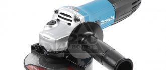
Universal models can be powered by both alternating and direct current. The advantage has significantly extended these units to domestic use. They are installed in various power tools, including grinders, screwdrivers, sewing and washing machines.
The windings of both components, namely the stator and the rotor, are made in series connection. Current is supplied to the last element performing rotation through special brushes. They come into contact with the commutator plates connected to the ends of the rotor coils.
The reversing effect occurs by changing the polarity of the inclusion of the stator and rotor in the power supply, and the speed is by varying the volume of current generated in the windings.
Flaws:
- a lot of noise - washing machines are proof. Modern washing machines are equipped with special parts that reduce noise;
- significant price;
- difficult control.
Machines used in everyday life are distinguished by mechanical switching with field coils (CB). The latter can be independent, parallel, or sequential. Mixed types of parts are often used. CDs equipped with permanent magnets do not have the disadvantage of high cost and management. They are easy to control, and to change the direction of rotation, just change the polarity.
Disassembly, inspection and preparation of the stator
You can do the rewinding yourself or send the electric motor for repair. Since the latter option often requires a lot of money and is not always feasible in small towns, it is best to rewind the winding yourself. In a home workshop this is quite feasible. Nowadays, three-phase AC electric motors with a squirrel-cage or phase-wound rotor are widely used. Therefore, the process of rewinding electric motors of this particular type will be discussed below. Rewinding, like replacing most other engine parts, begins with disassembling it.
After completing all safety preparations (turn off the power, disconnect the drive, etc.), the electric motor is thoroughly cleaned and washed in order to minimize the ingress of dirt inside.
Then unscrew several bolts of the fan and its casing, and then the fixing bearing shields. They are located on the end parts of the engine.
Having disassembled the engine, begin to remove the old winding. To do this, its protruding parts (frontal) are chipped off with a chisel from the side of the winding terminals.
The frontal part is cut down along the entire circumference of the stator.
After this, wedges are knocked out of the grooves, which fix the winding in the grooves, and then they are removed.
In small electric motors, as a rule, there are no wedges and the remaining winding can be immediately pulled out with pliers.
Having freed the stator from the damaged winding, it must be carefully inspected, cleaned and, if possible, blown with air. So, often after a short circuit to the housing, copper deposits, burrs and other metal defects remain in this place.
Most can be removed with fine grit sandpaper.
How to call
For high-quality diagnostics of the angle grinder stator, you should completely disassemble the power tool in order to remove all other structural elements, including the rotor, to ensure free access to all its parts. At the initial stage, it is necessary to perform a visual inspection. For a more complete picture, you should definitely check for defects using electrical instruments. What devices and how to ring the stator of an angle grinder are described in detail at the link “How to ring the stator of an angle grinder.”
Stator preparation
Now you need to place the insulating material into the stator grooves, having previously prepared it.
To do this, take measurements from the groove - measure its length and cut out a test section of material that fits into the groove.
The insulation should not protrude inward beyond the groove, and the creators protruded a length of more than 5 mm; the size of the protruding part depends on the material and the engine.
A dielectric fragment of the required size is called an insulating sleeve, and its insertion into the grooves is called a sleeve. Having decided on the size, cut out the required number of sleeves.
It’s better to immediately cut out the “arrows” - the insulating material covering the winding from the inside, from the open part of the groove.
They have the same length as insulating sleeves, and are half as wide.
Motor winding data
This is a reference data, so the most reliable way to obtain this information is to consult the appropriate sources. This data can also be provided in the product passport.
You can find advice online that recommends manually counting the turns and measuring the diameter of the wire when rewinding. It's a waste of time. It is much easier and more reliable to find all the necessary information using the engine markings, which will indicate the following parameters:
- rated operating characteristics (voltage, power, current consumption, speed, etc.);
- number of wires for one slot;
- Ø wire (as a rule, insulation is not taken into account in this indicator);
- information on the outer and inner diameter of the stator;
- number of grooves;
- with what step the winding is performed;
- rotor dimensions, etc.
Conductor preparation
At the next stage, a new winding is formed in accordance with the dimensions of the created template. However, before this you need to find out the characteristics of the winding - the diameter of the wire and how many turns there are in it. Such information can be found on the Internet or in the engine manual. Otherwise, this needs to be clarified during the rewinding process - after cutting out the frontal part of the winding. The number of turns is counted by the cut wires in one groove, and their diameter is measured with a micrometer.
It should also be borne in mind that the new winding should be formed according to the characteristics of the old one. When using a wire made of a different material or cross-section, you need to recalculate the resistance value. To do this, it is better to use tables with appropriate conversion factors. Having decided on the wire, we begin to form the winding. First, create a template, preferably from dense wire, remembering that the frontal parts of the winding should not stick out much, since they can touch the body. To wind the coils, special machines are used, the design of which includes two spikes fixed together by spacers.
They are placed at a distance corresponding to the template and fixed. Then, the wire is wound by rotating these spikes. The wire must be distributed evenly, trying not to overlap, as this will complicate further pouring of the winding into the groove. Having wound the required number of turns, you need to remove the spacer and remove the finished winding.
Required Tools
Solid forged metalworker's hammer 500 gr. Inforce. Photo VseInstruments.ru
Typical set of tools for repair.
- Various hammers : metal, wooden, several sizes.
- To manipulate the coils , pliers, round nose pliers, and pliers are used.
- Cleaning the stator surfaces from dirt and insulation is done using a metal brush.
- The required cleanliness of the stator surface can be achieved using an electric drill with appropriate attachments.
- In addition to the micrometer, for less critical measurements, calipers and a ruler are used.
- You can monitor the electrical parameters of the coils after rewinding with a multimeter.
- Cambrides, insulating cardboard, keeper tape, special varnish for impregnation are auxiliary materials for repair technology.
Conductor laying and insulation
Then the formed windings are placed in the groove, using for convenience a special tool - a tamper, which is used to compact the conductors poured into the groove.
It consists of an iron handle to which a rectangular plate is welded. Sprinkling is done by separating the windings into small bundles with your fingers and passing them through the open part of the groove.
After one side of the coil is poured into the groove, it is compacted with the tool described above and the other part begins to pour out in accordance with the pitch of the winding.
After laying the windings, close the surface facing the open part of the groove - insert the arrows previously cut from the insulation. In this way, the remaining sections of the winding are laid.
After this, it is necessary to insulate the coils of different phases in the frontal parts from each other. For this purpose, electric cardboard is used, from which circle-shaped figures are cut out and inserted between the phase coils.
Then the frontal part is tied so that the windings fit tightly to each other.
To do this, use nylon, special binding cord or taffeta tape. Before tying the frontal part, it is shaped by beating it with a rubber hammer. All procedures are performed from both creators - from the side of the circuit and from the opposite side.
The main part of the rewinding is almost finished. Tubes made of dielectric material are used to insulate the coil terminals. It is better to use TKR tubes, as they have greater heat resistance and will not melt during operation.
Before assembling the required circuit, make a continuity test between the phases using a megohmmeter, that is, measure the resistance between the coils belonging to different phases. Also, continuity testing is done between the phases and the housing. If the megohmmeter shows infinitely high resistance in both cases, then everything is in order and you can solder or weld the ends of the phase windings according to the desired circuit. Insulating tubes are put on the soldered ends of the wires, but with a larger diameter. Do not forget to compact the arrows, as they often protrude from the grooves.
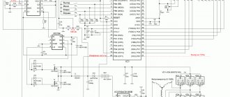
Capacitor starting circuits
Let me say right away that there are quite a large number of their developments in electrical engineering. I consider only the most popular ones. For them, it is necessary to select capacitors based on capacity and operating voltage.
Since the amplitude of the sine wave constantly changes its sign, only capacitors whose insulation is designed for 500 volts or more can be safely operated.
Launch scheme for star
The phase and zero potentials are applied to the beginnings of two windings, and the third is connected through capacitors. They are divided into two chains: a working chain, permanently mounted, and a starting chain, activated via a switch.
Sometimes a trigger circuit is used to overcome heavy loads. But you can’t work like this for a long time: the motor winding overheats and the insulation can burn out.
Trigger circuit for triangle
The principle of supplying voltage through chains of capacitors and a switch remains the same. The only peculiarity is that the potentials are supplied to the assemblies of the beginnings and ends of the windings.
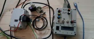
Startup circuit via a homemade converter
I present an option for developing the supply of phase-shifted currents to the delta windings.
· the active resistance of the resistor in one phase creates a current that matches the supplied voltage;
· the capacitor provides a 90-degree advance of the current;
An integrated approach ensures fairly good engine performance with high load resistance.
However, there is generally low efficiency and high electricity losses: the converter itself consumes as much energy as a three-phase motor. Its double expense is unlikely to pay off. An analysis of the operation of this scheme is presented in the article given at the first link.
Impregnation and drying
Next, you can begin impregnating the stator of the electric motor. Before impregnation, it is better to assemble the engine and again perform a continuity test between the coils and the housing, and also measure the current value during idle operation using a measuring clamp.
For impregnation, ML-92 varnish is used; instead, when impregnating at home, you can use the NTs brand, which dries faster and does not contain water-based additives.
The stator is immersed in a container of varnish and then suspended to remove excess. The impregnated stator is dried in an oven for 2 hours at a temperature of 120 °C. If NC type varnish was used, then oven drying lasts 20-30 minutes. The stator can also be dried in the open air for 3-4 hours.
- The final stage is engine assembly, after which the windings are checked again.
This must be done because during the drying process the insulation of the coils may become deformed and touch the motor housing. Thus, rewinding an electric motor with your own hands at home is quite feasible if you have some skills, materials and tools.
Causes of breakdowns
408-105 Stator for Hitachi G18SE3 and HAMMER angle grinders. Photo 220Volt
The most common cause of failure of the stator of an angle grinder is a violation of operating conditions . Asynchronous motors have the ability to maintain speed regardless of the magnitude of the current load. This is both an advantage and a disadvantage.
The ability to perform work under heavy loads is accompanied by overheating of the tool , which during long-term operation contributes to the occurrence of malfunctions in the rotor and stator windings . Under the influence of high temperatures, the protective layer of the insulating coating burns out, which leads to failure of electrical components.