Purpose and principle of operation of a voltage transformer
The measuring voltage transformer is used to reduce the high voltage supplied in alternating current installations to measuring instruments and protection and automation relays.
For direct connection to high voltage, very bulky devices and relays would be required due to the need to make them with high-voltage insulation. The manufacture and use of such equipment is practically impossible, especially at voltages of 35 kV and above.
The use of voltage transformers allows the use of standard measuring instruments for high voltage measurements, expanding their measurement limits; relay windings connected via voltage transformers can also have standard designs.
In addition, the voltage transformer isolates (separates) measuring instruments and relays from high voltage, thereby ensuring their safe operation.
Voltage transformers are widely used in high-voltage electrical installations; the accuracy of electrical measurements and electricity metering, as well as the reliability of relay protection and emergency automation, depend on their operation.
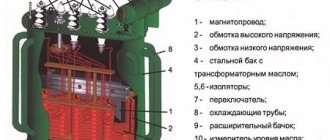
The operating principle of a voltage measuring transformer is no different from a power step-down transformer. It consists of a steel core made of electrical steel sheet plates, a primary winding and one or two secondary windings.
In Fig. 1a shows a diagram of a voltage transformer with one secondary winding. A high voltage U1 is applied to the primary winding, and a measuring device is connected to the voltage of the secondary winding U2. The beginnings of the primary and secondary windings are designated by the letters A and a, the ends by X and x. Such designations are usually marked on the body of the voltage transformer next to the terminals of its windings.
The ratio of the primary rated voltage to the secondary rated voltage is called the rated transformation ratio of the voltage transformer Kn = U1 nom / U2 nom
When a voltage transformer operates without errors, its primary and secondary voltages are in phase and the ratio of their values is equal to Kn. When the transformation ratio K n = 1, the voltage U 2 = U 1 (Fig. 1, c).
Legend: Z - one terminal is grounded; O - single-phase; T - three-phase; K - cascade or with compensation winding; F - with porcelain outer insulation; M - oil; C - dry (with air insulation); E - capacitive; D is a divisor.
The terminals of the primary winding (VN) are designated A, X for single-phase and A, B, C, N for three-phase transformers. The terminals of the main secondary winding (LV) are designated a, x and a, b, c, N, respectively; the terminals of the secondary additional winding are designated ad and xd.
The beginnings of the primary and secondary windings are connected to terminals A, B, C and a, b, c, respectively. The main secondary windings are usually connected in a star (connection group 0), the additional windings are connected according to an open delta circuit. As is known, in normal operation of the network, the voltage at the terminals of the additional winding is close to zero (unbalance voltage Unb = 1 - 3 V), and in the event of a ground fault it is equal to triple the value 3UО of the zero-sequence voltage UО of the phase.
In a network with a grounded neutral, the maximum value of 3U0 is equal to the phase voltage, with an isolated network - triple the phase voltage. Accordingly, additional windings are made for rated voltage Unom = 100 V and 100/3 V.
The rated voltage of a TV is the rated voltage of its primary winding; this value may differ from the insulation class. The rated voltage of the secondary winding is taken to be 100, 100/3 and 100/3 V. As a rule, voltage transformers operate in no-load mode.
Instrument voltage transformers with two secondary windings
Voltage transformers with two secondary windings, in addition to powering measuring instruments and relays, are intended to operate on earth fault signaling devices in a network with an isolated neutral or for protection against earth faults in a network with a grounded neutral.
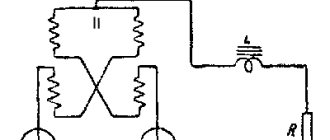
The circuit of a voltage transformer with two secondary windings is shown in Fig. 2, a. The terminals of the second (additional) winding, used for signaling or protection in case of ground faults, are designated hell and hd.
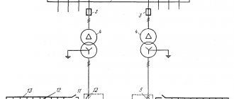
In Fig. 2.6 shows a diagram of the connection of three such voltage transformers in a three-phase network. The primary and main secondary windings are connected in a star. The neutral of the primary winding is grounded. Three phases and zero can be supplied to measuring instruments and relays from the main secondary windings. Additional secondary windings are connected according to an open delta circuit. From them, the sum of the phase voltages of all three phases is supplied to signaling or protection devices.
Rice. 2. Voltage transformer with two secondary windings. a - diagram; b - connection to a three-phase circuit; c - vector diagram
The sum of the vectors Uad, U b d and Ucd was obtained by combining them according to the connection diagram of additional windings, while it was assumed that the arrows of the vectors of both primary and secondary voltages correspond to the beginnings of the transformer windings.
The resulting voltage 3U0 between the end of the winding of phase C and the beginning of the winding of phase A on the diagram is zero.
The voltage that ensures reliable operation of relays connected to an open delta circuit occurs only when there is a ground fault on the side of the primary winding of the voltage transformer. Since ground faults are associated with the passage of current through the neutral, the resulting voltage at the output of the open delta according to the method of symmetrical components is called the zero-sequence voltage and is designated 3U0. In this designation, the number 3 indicates that the voltage in this circuit is the total for three phases. The designation 3U0 is also used for the open delta output circuit supplied to the alarm or protection relay (Fig. 2.6).
The voltage 3U0 has the greatest value during a single-phase ground fault. It should be borne in mind that the maximum voltage value 3U0 in a network with an isolated neutral is significantly greater than in a network with a grounded neutral.
Common circuits for connecting instrument voltage transformers
To detect “ground” using these voltmeters, they must show the values of the primary voltages between the phases and the ground (see vector diagram in Fig. 3.6). To do this, the zero of the HV windings is grounded and the voltmeters are switched on to the secondary phase voltages.
A feature of the open triangle circuit is the underutilization of the power of the transformers, since the power of such a group of two transformers is less than the power of a group of three transformers connected in a full triangle not by 1.5 times, but by √ 3 times.
If you liked this article, share a link to it on social networks. This will greatly help the development of our site!
Subscribe to our channel on Telegram!
Just follow the link and connect to the channel.
Don't miss updates, subscribe to our social networks:
Source
Connection diagrams for voltage transformers in open and open delta
An open delta connection means that the equipment is connected between the sides of two phases. In this case, electric current is conducted from the outside, from the secondary windings of a number proportional to this indicator. The relay and the main load are connected between the secondary network, which allows you to obtain the desired level of resistance.
This circuit allows you to connect three sources at a time. It should be noted that the supply is organized in a linear manner, and the passage of current from the first to the third source and vice versa must be avoided.
The open type of connection is used in rectifier equipment. Using a type connection, a current of triple frequency is achieved, which is impossible when working with a star or open symmetrical. An option is used when three transformers with one phase are connected to a device that increases proportionally the three operating frequencies.
Using the figure under consideration, a zero sequence is obtained, that is, in the normal functional UP will be equal to zero.
The neutral of the primary winding must be grounded, and for the secondary winding, parameters of at least 100 Volts are selected, if grounded. For an isolated one, the coefficient is taken to be 100 to 3 V. The coefficient is three times, therefore, the secondary windings sum up the transformation coefficient also three times. Therefore, for the example described above, it is 6 thousand to one hundred to three. The peak is obtained from the transformer windings of the outer surface, since the supply is carried out through the secondary. Grounding is required.
Note!
Ungrounded voltage transformers in (6-10) kV networks.
Ignatenko E.V., Chief Designer of OIT JSC Sverdlovsk Current Transformer Plant.
In accordance with the requirements of the regulations of PJSC "Rosseti" "On a unified technical policy in the electrical complex" and the PUE (edition 7), simultaneous connection to the measuring windings of current and voltage transformers involved in metering circuits, alarm and protection devices, automation or other electrical appliances is unacceptable. In other words, if a metering device is connected to the measuring winding, then nothing else can be connected to this winding. In connection with this requirement, a number of problems arise related to the operation of voltage transformers (VT).
To account for electrical energy, both grounded and ungrounded voltage transformers are used. The most common arrangement is three grounded VTs and three current transformers (CTs).
Grounded voltage transformers are manufactured in single-phase and three-phase versions. In my article we will talk about single-phase transformers that are connected into three-phase groups.
Grounded single-phase voltage transformers can be made with one or two secondary windings for measurement and metering, and one additional winding, which is designed to power protection circuits. Single-phase transformers are connected into a three-phase group, while the high-voltage windings are connected in a star with the neutral removed. The LV measuring windings are in a star, additional windings are connected according to an open delta circuit. The main purpose of grounded voltage transformers is to monitor network insulation in networks with an isolated neutral.
The rated voltage of the additional winding of a single-phase voltage transformer is, as a rule, 100/3 V. When connecting additional windings in an open delta circuit, in a symmetrical network mode, the voltage at the terminals ad - xd will not be zero, and should not exceed three volts. In the event of a single-phase ground fault, the voltage at the open delta terminals should be equal to 100 V. The ground fault alarm relay is designed for this voltage.
Often, grounded VTs are used only for electricity metering. In this case, the measuring windings are loaded onto the metering device, and the additional windings are either not used at all or are powered for their own needs. This mode of operation of grounded voltage transformers is determined by the requirements of the regulations of PJSC Rosseti “On a unified technical policy in the electrical complex” and the PUE. Such circuits are used in commercial metering points (CCPs), for powering GSM modules and heating electronic meters. When operating grounded voltage transformers with such circuit solutions, a number of problems are visible.
- As mentioned earlier, in a symmetrical mode of network operation, the voltage across an open delta does not exceed 3 V. The power consumed by additional windings tends to zero. The measuring winding is loaded in the range of 25% - 100)% of the rated power. This is the normal operating mode of the HP.
The mode when additional windings, in symmetrical network mode, are constantly powered to the load, will lead to overload of the transformer, which will affect the metrological characteristics of the transformer. Voltage errors will be outside the permissible range. If it is necessary for the transformer to operate in exactly this mode, this requirement is specified when ordering, and the secondary load must be symmetrical. During acceptance tests, the measuring winding will be verified for compliance with the specified accuracy class with all secondary windings simultaneously loaded.
2. The inclusion of an additional active resistance of 25 Ohms in an additional winding connected in an open triangle allows you to prevent ferroresonance in the network or significantly reduce its negative impact. If additional windings are not used or they are used as a voltage source, in the mode of short circuit of one of the network phases to ground, the current of the HV winding will not be limited. This will damage the VT. And in general, the resistance of voltage transformers to ferroresonant phenomena in networks in the case where additional windings are used for other purposes is not guaranteed. Testing (calculation) of transformers for resistance to ferroresonance is carried out under rated modes, which imply the inclusion of a secondary load of a nominal value set by the VT manufacturer in additional windings connected in an open delta circuit. Some manufacturers, to increase the reliability of voltage transformers, recommend installing other ferroresonance suppression devices, for example SZTn (developed by OJSC SZTT).
What to do when you need to create an metering system with voltage transformers, but at the same time you need to take power to power your own circuits?
Our enterprise has developed an ungrounded voltage transformer NOL.08.3-6(10)M with two secondary windings. The main winding is designed to power metering and measurement circuits, with accuracy classes 0.2; 0.5 or 1, according to GOST 1983-2015. The additional winding is intended to power the circuits for its own needs. Deviation of secondary voltage from nominal ±0.5%.
A three-phase group of ungrounded transformers is connected in a delta/delta/delta connection. The peculiarity of this transformer is that it is absolutely not affected by ferroresonance, since it does not have a grounded output of the high voltage winding, therefore, there are no conditions for the occurrence of ferroresonance. Additional windings can be loaded to power heating circuits, GSM modules and other purposes.
Another important advantage, compared to grounded transformers, is the ability to test the main insulation of transformers under operating conditions. The internal insulation of grounded voltage transformers is tested by induced voltage with a frequency from 100 Hz to 400 Hz, the choice of frequency is determined by the design of the voltage transformer. Test voltage level - in accordance with GOST 1516.3. As a rule, operating organizations do not have a high frequency voltage source. GOST 1516.3 allows testing of internal insulation with industrial frequency voltage, but the voltage level is no more than 1.3 rated. This test does not give a complete picture of the insulation condition of the transformer. Unlike grounded transformers, the internal insulation of ungrounded transformers can be tested by applied power frequency voltage. This means that they can be tested together with current transformers and the busbar of the high-voltage compartment.
The use of ungrounded voltage transformers in measurement and metering circuits leads to a reduction in losses from under-metering of electricity. Ungrounded instrument voltage transformers do not have all the disadvantages that are typical for grounded voltage transformers, therefore, at commercial metering points it is advisable to use the three-phase group 3xNOL.08.3-6(10)M.
Back
Top
Difference between connections
The main difference between an open triangle and an open one is that it can be used to obtain a zero-sequence voltage. In the case of an open connection, the values of the secondary terminals are always proportional to the phase-to-phase value.
But in any case, circuit breakers and fuses are used to protect transformers with such a circuit. If a phase is broken, a short circuit occurs.
Blocking with the help of automatic machines will avoid a surge, which leads to winding malfunctions. Control is carried out with the possibility of measurement.
Open triangle
An open triangle is used, for example, in rectifier installations to produce a triple-frequency current that biases an equalizing reactor (see the article “Six-phase star and double zigzag”, Figure 3, a) For this purpose, a frequency tripler , which consists of three single-phase transformers with highly saturated magnetic circuits. The primary windings of the frequency tripler are connected in a star with an insulated neutral, the secondary windings are connected in an open triangle (Figure 1, c). The strong saturation of the magnetic circuits, their low magnetic resistance, the impassability of the neutral of the primary winding for third harmonic currents - all this ensures the appearance in the secondary windings of an electromotive force (emf) of triple frequency, coinciding in time for all phases (see the article “The Concept of magnetic equilibrium of the transformer"). Therefore, a triple-frequency current passes through the UR, which closes the circuit of the secondary windings of the frequency tripler, which is what is required in this case (see the article “Six-phase star and double zigzag”).
Voltage transformers in high-voltage electrical installations and their secondary circuits
These transformers are used in high-voltage electrical installations to convert high voltage to a standard level of 100 V, suitable for processing by measuring instruments, relay protection and alarm devices.
In addition, they serve to isolate personnel and equipment from high voltages. High-voltage voltage transformers (hereinafter referred to as VTs)
They are divided according to the principle of operation into electromagnetic and capacitive voltage dividers.
Electromagnetic transformers
consist of HV and LV windings and a magnetic circuit. The principle of their operation is based on the excitation by the high-voltage windings of a flux in the magnetic circuit, which induces an EMF in the secondary windings.
By the magnitude of the EMF of the secondary windings, one can judge the magnitude of the primary voltage, taking into account the transformation ratio. Electromagnetic VTs
used up to 500 kV inclusive.
TN
35 kV is connected to the network through fuses so that damage
to the voltage transformers
does not cause an accident at the substation.
In electrical installations of 110 kV and above, VTs
are not protected from the high side and are switched on through a disconnector.
To protect the transformer
To protect against damage, fuses or circuit breakers are installed in secondary circuits.
To create a visible break in the secondary circuits, when the VT
for repair, switches are provided.
The most common TN
in networks 110-500 kV is NKF. It is assembled from single cascades, each of which is designed for 110 kV. The cascade is a single element in porcelain insulation filled with transformer oil.
The high voltage winding is wound on two rods of one magnetic circuit in order to reduce insulation. A connecting winding is used to connect two cascades to each other.
The main disadvantage of electromagnetic transformers, including NKF, is the nonlinearity of their current-voltage characteristic.
When connecting capacitive network elements and an electromagnetic transformer in series and series-parallel with a nonlinear current-voltage characteristic, ferroresonance occurs. This phenomenon is accompanied by a significant increase in current, the thermal effect of which leads to the destruction of the voltage transformer
and even its fire.
Capacitive voltage dividers
. Dividers are most widespread in electrical installations of 500 kV and above. If four coupling capacitors are connected in series at a voltage of 500 kV, the voltage between them will be divided in accordance with their capacitance.
The divider is based on the inverse relationship between the applied voltages and the capacitances of the capacitors. So, by selecting three capacitors with a capacity of 0.014 μF and one capacitor with a capacity of 0.107 μF, and connecting them in series, the voltage between the elements will be divided in an inverse relationship.
The first three capacitors will have 485 kV, and the last one with the largest capacity will have 15 kV. The signal from the voltage divider is taken from a capacitor to which a voltage of 15 kV is applied, so there is no need to use bulky equipment for processing the secondary signal.
Domestic dividers are marked NDE. Each is assembled from several SMR type capacitors, designed for 166 kV and one OMR power take-off capacitor. The number of unit capacitors depends on the magnitude of the primary voltage.
To the VT
on the low side, a high-frequency suppressor is switched on in series. It prevents high frequency signals from entering the secondary circuits from the line. In addition to the RF jammer, a reactor is installed in order to disrupt possible resonance phenomena.
TN connection diagrams
.
Secondary circuits of voltage
transformers in electrical installations of 110 kV and above, regardless of the principle of connecting the primary circuits, are connected to the secondary busbars in the same way.
So three single-phase transformers are connected into a three-phase group with a star-star winding connection with grounding of the high and low side neutrals. This connection diagram makes it possible to measure linear and phase voltage.
The additional winding of the transformers is connected in an open delta and in normal mode there is no voltage on it. It is used to check the serviceability of 3U0 circuits and when checking ground fault protection.
The secondary windings of transformers connected in a star configuration are used to measure line and phase voltages. Windings connected in an open delta circuit are used to measure the phase insulation resistance relative to ground in networks with an isolated or compensated neutral.
To reduce the number of switching devices in VT
, the secondary winding of phase b is grounded, and its serviceability is monitored by voltage relative to the other two phases.
Modern HP
manufactured by ALSTOM, ABB, Siemens have a more compact structure in comparison with outdated types NKF and NDE.
Despite the voltage class of the electrical installation, new transformers
are made as single-stage ones.
Maintenance of modernized HP
consists only of periodic high-voltage tests and inspections of equipment.
VT
windings are immersed in dry transformer oil and hermetically sealed with a metal cap. Thermal expansion of the oil is compensated by a bellows device located in the head of the equipment.
VT secondary circuits
located in close proximity to the equipment to reduce the risk of damage.
Boxes with VT
are placed on racks under the equipment.
In what cases is it used?
The schematic construction of an open-loop version for a transformer is used quite often in production. The fact is that thanks to it you can use synchronization on power vehicles. Used to connect transformers with one phase if it is not possible to install a three-phase one. Protects mechanisms, including electric motors, from supplying two if there is no voltage in one of the phases. The only acceptable assembly scheme is if the rotor is installed in the stator bore.
Voltage transformer design
Like all transformers, as mentioned above, this type of transformer has both primary windings (high voltage) and secondary windings (low voltage). There are single-phase and three-phase voltage transformers.
Each of them has a magnetic circuit, which is subject to fairly high requirements. The fact is that the greater the dissipation of the magnetic flux in such a transformer, the greater the measurement error. By the way. Depending on the error, transformers are classified into different accuracy classes (0.2; 0.5; 1; 3). The higher the number, the greater the measurement error.
For example, a transformer with an accuracy class of 0.2 can allow an error of no more than 0.2% of the measured voltage value, and, accordingly, an accuracy class of 3 - no more than 3%.
The designations on the diagrams and the natural design can be very different from each other.
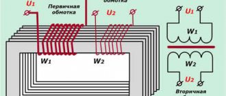
A single-phase two-winding transformer is shown in the figure as it actually looks.
In the diagrams it is designated as:
Please note that the transformer is a step-down, there are fewer turns in the secondary winding than in the primary, and this is reflected visually in the diagram in this case, although this is not always done. In addition, the beginnings and ends of the windings are indicated on the diagram and on the transformer itself. Primary windings are designated by large (capital) letters A and X. Secondary - small (lowercase) letters a and x.
There are also three-winding single-phase transformers that have two secondary windings. One of which is the main one, and the second is additional. The additional winding serves to control insulation and has the abbreviation KIZ. The markings of the terminals of this winding are as follows: ad - the beginning of the winding, xd - the end of the winding.
Three-phase transformers are available with two types of magnetic cores: three-rod and five-rod.
Beginnings and endings are designated slightly differently here. On the primary windings, the beginnings are designated by the letters A, B and C according to the phases to which they will be connected, and the ends by the letters X, Y and Z. The secondary windings, respectively, by small letters a, b, c and x, y, z.
The magnetic fluxes created by the AX, BY, CZ coils compensate each other under normal operating conditions. But in the event of a breakdown of one of the phases to the ground, too much imbalance is created in the magnetic cores and part of the flux will be looped through the air, which creates strong heating of the transformer due to an increase in the rated current in the windings. Additional rods are precisely designed to take over the resulting unbalanced flows and prevent overheating of the transformer. At the same time, additional windings are wound in it, but more on that later.
Vector diagram of triangle connection
A phasor diagram is a way of representing alternating voltages and currents using vectors.
Vector diagram of a three-phase EMF system and graph of the EMF of phases A, B and C:
Vector diagram of a three-phase symmetrical EMF system:
Vector diagram of voltages of a symmetrical load connected by a star:
Constructing a voltage diagram of a symmetrical load connected by a star:
Vector diagram of the currents of an active asymmetrical load connected by a star:
Construction of a vector diagram for an asymmetrical load when the neutral wire is broken:
Asymmetrical load when the neutral wire is broken:
Constructing a diagram for an asymmetric load. Star without neutral wire:
Vector diagram of a symmetrical load connected by a star:
Vector diagrams of voltages and currents when connecting receivers with a triangle:
Vector diagram of voltages and currents when connecting receivers with a triangle:
Vector diagram of voltages and currents when connecting receivers with a triangle (unbalanced load):
Vector diagram of voltages and currents of an asymmetric load connected by a triangle:
Features of connecting three-phase systems with a triangle.
The vector diagram for connecting the generator windings according to a triangle diagram is shown in Fig. 4.5, b
. This diagram assumes that the generator voltage vectors have the values
i.e. the generator is considered symmetrical with direct phase rotation.
When the loads are connected by a triangle, the phase voltages will be equal to the linear ones, and the linear currents will be equal to the geometric difference of the two phase currents approaching the apex of the load triangle, as shown in Fig. 4.6. In this case, for the positive directions of currents the following relations are valid, which establish the connection between linear and phase currents
Phase currents are calculated based on known linear voltages and conductivities YAB, YBC, YCA of the receiver phases
From equations (26.2) it also follows that for any values of phase currents the following expression is valid for linear currents:
It should be noted that switching on loads according to a delta circuit is possible with any connection of the generator windings, both in a delta circuit and in a star circuit. However, when the generator is turned on in a star circuit, the phase voltages of the receiver will be equal to the linear voltages of the generator. In this case, the zero point of the generator is not used.
Let's consider some particular operating modes when switching on loads according to a triangle diagram. These modes include:
□ uniform load of generator phases;
□ uneven load of generator phases;
□ break of one phase of the receiver;
□ break of two phases of the receiver;
□ line wire break.
A short circuit of any phase of the receiver leads to an emergency mode, since this short-circuits one of the generator windings, and is therefore unacceptable.
Uniform load of generator phases.
With a symmetrical system of generator voltages, determined by equations (4.1) and the same load on the receiver phases (YAB = YBC = YCA = Yn), the effective values of the currents in the phases are equal to each other, therefore the linear currents are related to the phase currents by the relation
Currents in the phases of the receiver are determined by formulas (4.3) and, if the conductivities are equal, have the values
The vector diagram for uniform load of generator phases is shown in Fig. 4.7 a
Uneven load of generator phases.
Uneven load of generator phases is the most common operating mode of a three-phase system. An uneven load is characterized by different values of the conductivities included in the receiver, i.e. YAB = YBC = YCA
. The effective values of currents in the phases of the receiver with an uneven load and a symmetrical generator are proportional to the load conductivities and are determined by formulas (26.3).
Connection diagrams for voltage transformer windings
The simplest way to measure phase-to-phase voltage is to connect a single-phase two-winding voltage transformer according to the diagram shown in the figure on the left.
In this case, at the ends of the secondary winding we have a voltage corresponding to the interphase BC, but reduced taking into account the transformation ratio.
All three phase-to-phase voltages can be measured using two single-phase transformers connected in a certain way.
In three-phase transformers, the primary windings are always connected in a star configuration.
The secondary windings can be connected either in a star or delta configuration.
With the top connection at the output points of the secondary winding, we have the ability to measure phase-to-phase voltages. With a lower connection, according to the so-called open delta circuit, we can detect the fact of a short circuit or wire break in one of the phases on the high side. The terminals are marked 01 and 02, since under normal operating conditions there is no voltage between these points.
To connect the protection relays, as mentioned above, additional windings in three-winding voltage transformers are used. Here is an example of connecting such transformers to a three-phase network. In this case, the ends of the windings are grounded in both the primary and secondary windings.
Here are a few more options for connecting single-phase transformers for measuring phase-to-phase and phase-to-phase voltages, as well as for powering control equipment.
More complex options for connecting voltage transformers containing a larger number of windings are studied in a special electrical engineering course.
Write comments, additions to the article, maybe I missed something. Take a look at the site map, I will be glad if you find anything else useful on my site.
Diagram of an incomplete and complete triangle and features of the operation of relay protection and automation according to these diagrams.
Connection diagram with 2 CTs and one relay connected to the difference between the currents of two phases (partial delta).
— the circuit is used to protect against phase-to-phase damage.
- in normal mode and during a 3-phase circuit, a current flows in the relay winding, which is > Iph.
— the protection has low sensitivity for 2-phase short circuit AB and BC, therefore sensitivity in
less than the sensitivity of protection circuits a, b.
Because of these shortcomings, it is used to protect electricity. engines.
In case of short circuit between AS Kch = Kch according to full and incomplete star schemes Kch =
Connection diagram of the CT in Δ, and the relay windings in Y (full triangle diagram).
1. Power supply system in which this scheme is used.
2. Equivalent circuit with Ikz
Disadvantage: Difficult and expensive.
Current flows in the relay for all types of short circuit, therefore the protection will work in all cases. When a ground fault occurs, the circuit is not very sensitive. This is due to the fact that with these types of short circuit, 0-sequence currents arise that do not go beyond the limits of Δ CT.
In this case, Q3 is protected by a full Δ circuit.
Maximum current relay RTV, RTM. MTZ with independent time delay on alternating operating current with de-shunting of the circuit breaker tripping coils.
An overcurrent relay with a mechanical time delay PTB, made on a solenoid-type electromagnetic system (Fig. 1), has a limited dependent time characteristic.
When sufficient force appears in the relay coil, the armature is attracted to the fixed pole. The force is transmitted through the spring as a rigid connection to the hammer and pushes it upward. The movement of the striker is prevented by the clock mechanism, with
by which it is connected by traction. The speed of movement is determined by the current strength in the relay, which determines the dependent part of the characteristic (Fig. 2).
After the time delay has expired, the striker is released and, striking the lever of the trip roller, releases the switch mechanism.
Starting with currents of approximately 3 times the actuation current, sufficient force is developed to compress the spring, causing the core to retract instantly. In this case, the speed of movement of the striker is determined by the properties of the spring and the braking effect of the mechanism and does not depend on the current strength in the relay, which provides an independent part of the characteristic.
Overcurrent relay RTM
The RTM instantaneous maximum current relay does not have a clock mechanism and differs from the RTV in a wide range of operating current settings (up to 150 A). There are instantaneous relay designs in which the operating current is regulated smoothly by changing the initial distance from the core to the fixed pole.
Due to the simplicity of protection circuits with RTM and RTV direct action relays, these relays are used for protection in rural power supply systems.
Electromagnetic solenoid drives PS-10, PS-30 do not have built-in relay coils. To perform protection with power supply to operational circuits directly from current transformers, a special attachment to the drive is used.
In addition to those mentioned earlier, they use instantaneous minimum voltage relays RNM and time-delay relays RNV.
Schemes with deshunting of switch tripping electromagnets are made using electromechanical relays (with dependent and independent time delay characteristics).
(4.20) where IВ03 and 1ср are the return and operation currents of the de-shunting relay. The corresponding primary current (4.21) The magnetizing current 1us can be found from the experimental characteristic U2 = f(I2) or from the CT error curves. 4. Reliability of operation is checked
Features of load connection circuits to a thyristor regulator
Most often in practice, four schemes for connecting loads to a thyristor regulator are used: star, triangle, star with working neutral and open delta.
Star and delta connection diagrams are shown in Figure 1.
Figure 1. Connecting a load to a three-phase thyristor regulator using star and delta circuits
The main advantage of these two circuits is their simplicity and minimal amount of power wire, due to which they are most widely used. When the load is connected by a star, the maximum voltage across the load resistance is equal to the phase voltage Uph, and when connected by a triangle - to the linear voltage Ul. Accordingly, a star is connected to a load designed for a voltage of 220 V, and a triangle is connected to 380 V.
The curve of the current flowing through the phase wire is shown in Figure 2.
Figure 2. Phase current curve for star or delta connection, resistive load
However, the simplicity of the circuit has a downside - the voltages across the load resistances are distributed equally only if the phase voltages are strictly equal (Uа = Ub = Uс) and the load resistances are equal (Ra = Rb = Rc or Rab = Rbc = Rca). As a rule, in practice this condition is almost never met and a voltage imbalance occurs: unequal voltages are established at different load resistances with the thyristors fully turned on, for example, at one resistance 210 V, at another 215 V, at the third 230 V.
For the most part, these unbalances are small: the voltage spread is small and amounts to no more than 4-8%, which is quite acceptable. But sometimes, if the parameters are poorly correlated - a strong “skew” of phases with simultaneously unequal load resistances - the voltages can be distributed with a large spread, for example, 190, 220 and 250 V. This leads to uneven wear of the heating elements and premature burnout of one of them.
Quite often it happens that in one of the phases the heating element constantly burns out for no apparent reason. This is usually a consequence of the phenomenon described above.
In connection diagrams of a star with a working neutral and an open triangle (Figure 3), this phenomenon manifests itself to a much lesser extent.
Figure 3. Connecting loads according to star circuits with working neutral and open delta
When the load is connected according to a star-zero circuit, the maximum voltage at the load resistance is equal to the phase voltage of the network, while the current of each phase is determined only by the phase voltage and the resistance of the load resistor included in this phase, and does not depend on the voltages of other phases and on the resistances of the remaining load resistances, that is, Ia = Ua / Ra, Ib = Ub / Rb, Ic = Uc / Rc.
Another important property of the circuit is the ability to equalize currents, voltages and powers at the load resistances in the event of a “misalignment” of the phases of the supply network. For example, thyristor current regulator can automatically adjust the load voltage so that equal power is allocated at each load resistance. This helps to extend the service life of heating elements, as well as energy saving - by eliminating phase imbalances, additional energy savings of 1-3% are achieved.
Another advantage of this circuit is the lower level of radiated electromagnetic interference.
All of the above is also true for an open delta circuit, with the only difference being that the maximum voltage across the load resistances is equal to linear, and the load current is determined by the linear voltage Iab = Uab / Rab, Ibc = Ubc / Rbc, Ica = Uca / Rca.
The star-neutral circuit has two disadvantages. The first is the need to connect the neutral wire, which in practice is sometimes difficult. For example, a heating apparatus may have three terminals for connecting phase wires, and the common point of the star is inside the apparatus and is not accessible for connection. In this case, it is impossible to implement a star-neutral connection.
The second drawback is the flow of current through the neutral during phase-pulse control, even with completely equal load resistances and phase voltages, which is illustrated in Figure 4: in the upper part there are current curves flowing through phases A, B and C, and at the bottom - the current in the neutral wire.
Figure 4. Current flow through the neutral conductor
In this case, the current value in the neutral wire can be 1.5-2 times greater than the current in the phases. This leads to the need to lay a neutral conductor with an increased cross-section, which, of course, increases the cost of cable lines. Ignorance or underestimation of this phenomenon leads to gradual failure of the neutral wire.
This sometimes causes surprise: it would seem that the phase voltages are equal, the phase resistances are equal, where does the current come from at zero?! But this phenomenon is explained simply. The fact is that with phase-pulse control of thyristors, the current shape becomes non-sinusoidal and therefore the currents in the neutral wire are not fully compensated, as when a three-phase load is supplied with a sinusoidal current.
Hence the conclusion - in order for the current in the neutral wire to be minimal, it is necessary to use period skip control. In this case, the phase currents will be sinusoidal, which means the current in the neutral will be determined only by the imbalance of phase voltages and resistances. In practice, this leads to the fact that the current at zero becomes no more than 10% of the phase current.
Finally, consider the open triangle connection diagram. The circuit has a remarkable property - thyristors with such a connection do not switch phase currents, but linear ones, which are 1.73 times less. For example, if the phase current is 650 A, then the currents in the linear wires are Il = 650 / 1.73 = 380 A. Compared with a conventional delta connection diagram, this makes it possible to purchase a thyristor regulator with a lower rated current, which is correspondingly cheaper and smaller in dimensions. This is shown in Figure 5. In the upper part of the figure, the load is connected by a triangle, while currents of 650 A flow through the thyristors, which means it is necessary to purchase a thyristor regulator with a rated current of at least 700-800 A. And in the lower part, the load is connected by an open triangle, while the phases carry the same current of 650 A, but since thyristors switch a current of 380 A, it is enough to have a thyristor regulator with a rated current of 400-500 A, which is 1.5-2 times cheaper.
Figure 5. Comparison of triangle and open triangle circuits
It’s a pity, but despite this advantage, this scheme has not become widespread. Why? First, as for a star with a neutral, to implement such a connection scheme, both ends of the load terminals must be accessible, which, again, is not always possible. For example, a transformer, the primary winding of which is connected by a triangle, most often has only three ends brought out, and the second three are hidden inside. The second is the increased cost of cable management - look carefully at Figure 5: when connecting with an open delta, an additional power cable is required (“return” cable from the load). Considering the high cost of cables, we can say that such a scheme is advisable only for short cable line lengths of up to 20-30 meters when laid with copper cable and up to 50-70 meters when laid with aluminum. With a long length, the savings obtained from purchasing a cheaper regulator are nullified due to the higher cost of cable management.
Connection diagrams for voltage transformers in open and open delta
An open delta connection means that the equipment is connected between the sides of two phases. In this case, electric current is conducted from the outside, from the secondary windings of a number proportional to this indicator. The relay and the main load are connected between the secondary network, which allows you to obtain the desired level of resistance.
This circuit allows you to connect three sources at a time. It should be noted that the supply is organized in a linear manner, and the passage of current from the first to the third source and vice versa must be avoided.
The open type of connection is used in rectifier equipment. Using a type connection, a current of triple frequency is achieved, which is impossible when working with a star or open symmetrical. An option is used when three transformers with one phase are connected to a device that increases proportionally the three operating frequencies.
Using the figure under consideration, a zero sequence is obtained, that is, in the normal functional UP will be equal to zero.
The neutral of the primary winding must be grounded, and for the secondary winding, parameters of at least 100 Volts are selected, if grounded. For an isolated one, the coefficient is taken to be 100 to 3 V. The coefficient is three times, therefore, the secondary windings sum up the transformation coefficient also three times. Therefore, for the example described above, it is 6 thousand to one hundred to three. The peak is obtained from the transformer windings of the outer surface, since the supply is carried out through the secondary. Grounding is required.
General information
Voltage transformers, as a rule, are a type of transformer that are designed not to transmit power, but to galvanically separate the high-voltage side from the low-voltage side.
Such transformers are designed to power measuring and control devices. On the “high” side of various voltage transformers, naturally, the voltage can be different, it can be 6000, 35,000 volts and even much more, but on the “low” side (on the secondary winding) it does not exceed 100 volts.
This is very convenient for unifying control devices. If you make measuring and control devices, and these are mainly relays, for high voltage, then, firstly, they will be very large, and secondly, very dangerous to maintain.
The transformation ratio is indicated on the transformer itself and can look like Ku = 6000/100, or simply 35000/100. Dividing one number by another, we get in the first case this coefficient is 60, in the second 350.
These transformers are available as “dry” transformers, in which electrical cardboard is used as insulation. They are usually used for voltages up to 1000 volts. Example NOS-0.5. Where, H means voltage, meaning a voltage transformer, O - single-phase, C - dry, 0.5 - 500 volts (0.5 kV). And also oil ones: NTMI, NOM, 3NOM, NTMK, in which oil plays the role of both an insulator and a cooler. And cast, to be precise, with cast insulation (3NOL - three-winding single-phase voltage transformer with cast insulation), in which all windings and the magnetic circuit are filled with epoxy resin.
Difference between connections
The main difference between an open triangle and an open one is that it can be used to obtain a zero-sequence voltage. In the case of an open connection, the values of the secondary terminals are always proportional to the phase-to-phase value.
But in any case, circuit breakers and fuses are used to protect transformers with such a circuit. If a phase is broken, a short circuit occurs.
Blocking with the help of automatic machines will avoid a surge, which leads to winding malfunctions. Control is carried out with the possibility of measurement.
Open triangle
An open triangle is used, for example, in rectifier installations to produce a triple-frequency current that biases an equalizing reactor (see the article “Six-phase star and double zigzag”, Figure 3, a) For this purpose, a frequency tripler , which consists of three single-phase transformers with highly saturated magnetic circuits. The primary windings of the frequency tripler are connected in a star with an insulated neutral, the secondary windings are connected in an open triangle (Figure 1, c). The strong saturation of the magnetic circuits, their low magnetic resistance, the impassability of the neutral of the primary winding for third harmonic currents - all this ensures the appearance in the secondary windings of an electromotive force (emf) of triple frequency, coinciding in time for all phases (see the article “The Concept of magnetic equilibrium of the transformer"). Therefore, a triple-frequency current passes through the UR, which closes the circuit of the secondary windings of the frequency tripler, which is what is required in this case (see the article “Six-phase star and double zigzag”).
ELECTROlaboratory
Good day, dear friends!
Today we will continue our conversation about instrument transformers. Let's talk about voltage transformers.
In the course of my work, I most often come across the following types of voltage transformers: STMI, which is now being replaced by NAMI and ZNOL.
Purpose of voltage transformers (VT
).
At voltages above 1000 V, direct switching on of devices is unacceptable both due to insulation conditions and the safety of operating personnel. In this regard, at high voltages, measuring instruments are switched on through intermediate instrument transformers, called voltage transformers (VTs).
VTs are designed both for measuring voltage, power, energy, and for powering automation, synchronization and relay protection of power lines from ground faults.
Designations of some voltage transformers most used in electrical installations.
NOM – TN. Single-phase, oil;
ZNOM – grounded HV input, voltage, single-phase, oil;
STMI – voltage, three-phase, oil, with a winding for monitoring network insulation;
Figure 1. Appearance of VT NTMI-6(10) kV.
Figure 2. Connection diagram of the windings of the TNMI-6(10) kV voltage transformer.
NAMI - voltage, anti-resonance, oil, with a winding for monitoring network insulation;
Figure 3. Appearance of TN NAMI-6(10) kV.
Figure 4. Connection diagram of TN NAMI-6(10) kV windings.
NKF - voltage, cascade, in a porcelain cover;
SR – series of voltage transformers: measuring, single-phase, capacitive with voltage 110-500 kV.
NOL.11-6.05; NOL.0.8; NOL.12; NOL – ungrounded voltage transformers 3-6-10 kV;
ZNOL.06; ZNOLE-35; ZNOL – grounded voltage transformers;
ZxZNOL; ZxZNOLP – three-phase anti-resonance groups TN;
Figure 5. Appearance of TN 3xZNOL-6(10) kV
Figure 6. Connection diagram of TN 3xZNOL-6(10) kV windings.
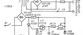
I would like to note that in high-voltage metering units installed on 10 kV overhead lines instead of resistors R1; R2; R3 (2.4 kOhm) one resistor R (0.8 kOhm) is installed. A frequently occurring defect is insulation burnout at the point of connection between the terminal X of the VT and resistor R1 (R2 or R3), which leads to a blown fuse in the phase in which the damaged resistor is located.
ZNOLP; NOLP – grounded and ungrounded transformer transformers with built-in protective safety devices. In transformers of these series, the high-voltage terminals of the primary winding are made with built-in protective safety devices (PSD), which, like the magnetic core with windings, are filled with an insulating compound, forming a monolithic block. The ZPU is made in the form of a collapsible structure with a fuse-link, which is a metal-dielectric resistor selected for each type of transformer. This device operates at currents less than 1 A, the shutdown time is from 5 to 10 seconds. After operation, the ZPU is subject to recharging, which is carried out by the personnel of the enterprise operating the transformer.
Figure 7. VT location in a high voltage cell.
What voltage is accepted in the secondary winding of the VT
.
For the main secondary winding of a VT with a rated voltage corresponding to the linear voltage of the network, the voltage is set to 100 V. Accordingly, for a VT with a phase rated voltage of the main secondary winding of 100 /V, when they are connected according to a star-star circuit, the secondary linear voltage corresponding to the rated one will also be 100 IN.
The rated voltage of the additional secondary windings is set in such a way that the maximum voltage value 3Uо (on an open delta) in the event of a single-phase ground fault in the network, when the line voltage corresponds to the rated voltage of the VT, is 100 V. Therefore, for additional VT windings intended for a grounded network neutral, set Unom = 100 V, and in a network with an isolated neutral Unom = 100/3 V.
Voltage transformers are manufactured with the following internal insulation design:
· Dry (voltage transformers up to 10 kV inclusive, type NOSK-6, ZNOLT-3, ZNOLT-6, ZNOLT-10, etc.).
· Oil-paper (transformers with voltage up to 35 kV inclusive, type NOM-10, NOM-35) with insulation of winding terminals at the full rated voltage.
· Cast epoxy (Czech single-phase voltage transformers and NOL type transformers).
TN tests.
Scope of voltage transformer testing:
1) measurement of the insulation resistance of the primary and secondary (secondary) windings (K, M)
2) high voltage testing of voltage transformers with cast insulation (K, M).
3) testing transformer oil (K, M). I would like to note right away that in transformer voltages up to 35 kV, transformer oil may not be tested
Note: K – major overhaul, testing upon acceptance into operation; M – overhaul tests
for voltage transformers 3-35kV
- when carrying out repair work in the cells where they are installed, if work is not carried out - at least once every 4 years.
The measured insulation resistance values during commissioning and operation must be no less than the values given in Table 5.
High voltage tests should be carried out in accordance with Table 6 or the requirements of the manufacturers.
That's all I have for today. If you have questions, ask, we will look for answers together.
Good luck!
In what cases is it used?
The schematic construction of an open-loop version for a transformer is used quite often in production. The fact is that thanks to it you can use synchronization on power vehicles. Used to connect transformers with one phase if it is not possible to install a three-phase one. Protects mechanisms, including electric motors, from supplying two if there is no voltage in one of the phases. The only acceptable assembly scheme is if the rotor is installed in the stator bore.
Vector diagram of triangle connection
A phasor diagram is a way of representing alternating voltages and currents using vectors.
Vector diagram of a three-phase EMF system and graph of the EMF of phases A, B and C:
Vector diagram of a three-phase symmetrical EMF system:
Vector diagram of voltages of a symmetrical load connected by a star:
Constructing a voltage diagram of a symmetrical load connected by a star:
Vector diagram of the currents of an active asymmetrical load connected by a star:
Construction of a vector diagram for an asymmetrical load when the neutral wire is broken:
Asymmetrical load when the neutral wire is broken:
Constructing a diagram for an asymmetric load. Star without neutral wire:
Vector diagram of a symmetrical load connected by a star:
Vector diagrams of voltages and currents when connecting receivers with a triangle:
Vector diagram of voltages and currents when connecting receivers with a triangle:
Vector diagram of voltages and currents when connecting receivers with a triangle (unbalanced load):
Vector diagram of voltages and currents of an asymmetric load connected by a triangle:
Features of connecting three-phase systems with a triangle.
The vector diagram for connecting the generator windings according to a triangle diagram is shown in Fig. 4.5, b
. This diagram assumes that the generator voltage vectors have the values
i.e. the generator is considered symmetrical with direct phase rotation.
When the loads are connected by a triangle, the phase voltages will be equal to the linear ones, and the linear currents will be equal to the geometric difference of the two phase currents approaching the apex of the load triangle, as shown in Fig. 4.6. In this case, for the positive directions of currents the following relations are valid, which establish the connection between linear and phase currents
Phase currents are calculated based on known linear voltages and conductivities YAB, YBC, YCA of the receiver phases
From equations (26.2) it also follows that for any values of phase currents the following expression is valid for linear currents:
It should be noted that switching on loads according to a delta circuit is possible with any connection of the generator windings, both in a delta circuit and in a star circuit. However, when the generator is turned on in a star circuit, the phase voltages of the receiver will be equal to the linear voltages of the generator. In this case, the zero point of the generator is not used.
Let's consider some particular operating modes when switching on loads according to a triangle diagram. These modes include:
□ uniform load of generator phases;
□ uneven load of generator phases;
□ break of one phase of the receiver;
□ break of two phases of the receiver;
□ line wire break.
A short circuit of any phase of the receiver leads to an emergency mode, since this short-circuits one of the generator windings, and is therefore unacceptable.
Uniform load of generator phases.
With a symmetrical system of generator voltages, determined by equations (4.1) and the same load on the receiver phases (YAB = YBC = YCA = Yn), the effective values of the currents in the phases are equal to each other, therefore the linear currents are related to the phase currents by the relation
Currents in the phases of the receiver are determined by formulas (4.3) and, if the conductivities are equal, have the values
The vector diagram for uniform load of generator phases is shown in Fig. 4.7 a
Uneven load of generator phases.
Uneven load of generator phases is the most common operating mode of a three-phase system. An uneven load is characterized by different values of the conductivities included in the receiver, i.e. YAB = YBC = YCA
. The effective values of currents in the phases of the receiver with an uneven load and a symmetrical generator are proportional to the load conductivities and are determined by formulas (26.3).
Monitoring the health of voltage circuits
Open delta voltage transformer connection diagram
Connection diagram of voltage transformer windings in an open delta
Star voltage transformer connection diagram
Voltage transformer connection diagrams
The circuit is designed to obtain phase voltages relative to ground and line voltages.
Grounding the neutral of the primary winding of the transformer and the presence of a neutral wire in the secondary circuit is a prerequisite for obtaining phase voltages relative to the ground.
Relay windings 1,2,3 are connected to phase voltages; 4,5,6 – for linear voltages.
The VT connection according to the Y/Y can be performed in 6 and 12 groups. A typical connection is group 12.
In Fig. 6.3.1: F – fuse; FA – fuse in relay protection circuits
The considered connection diagram can be made using three single-phase VTs or one three-phase five-rod VT (Fig. 6.3.2). Three-phase three-rod VTs are not used, since in their magnetic circuit there is no path for closing the zero-sequence magnetic fluxes Ф0 , created by the current I0 in the primary windings at ground fault in the network. Flow F0 is closed through the air, this sharply increases INAM , causing unacceptable heating of the transformer.
Additional winding on the main or additional rods is possible to obtain a zero-sequence voltage (Fig. 6.3.2).
Rice. 6.3.1
Rice. 6.3.2
Two single-phase VTs are connected to two phase-to-phase voltages. Relays are switched between the secondary circuit wires. The circuit allows you to obtain 3 phase-to-phase voltages.
Rice. 6.3.3
The connection diagram shown in Fig. 6.3.4, allows you to obtain the zero-sequence voltage:
(6.4)
In normal mode UP =0.
A necessary condition for the operation of the circuit is the grounding of the neutral of the primary winding of the VT. If there is no grounding, there will be no voltage to the relay. For the secondary winding, UNOM = 100 V is accepted - for networks with a grounded neutral and 100/3 V - for an isolated one. Practically under normal conditions, the voltage on the relay is Unb = 0.5...2 V.
For a single-phase short circuit in a network with a grounded neutral (Fig. 6.3.5):
UA=0; UB+UC=UФ=UP .
In a network with an isolated neutral (Fig. 6.3.6): UP = 3UФ, therefore, VTs intended for such networks have secondary windings with a transformation ratio increased by 3 times (for example: 6000/100/3).
Rice. 6.3.4
Rice. 6.3.5
Zero sequence voltage can also be obtained from special windings of three-phase voltage transformers (see Fig. 6.3.2). VTs with two secondary windings are most often used. One is connected in a star pattern, and the second is connected in an open triangle (see Fig. 4.3.1 b).
The secondary windings of VTs are subject to mandatory grounding. It is protective, ensuring the safety of personnel when high voltage enters the secondary circuits. Usually the star point or one of the phase wires is grounded. The wires connecting the grounding point to the VT windings should not contain switching or protective devices.
Rice. 6.3.6
Damage in the secondary circuits of voltage transformers (short circuits and breaks) can damage relay protection equipment or lead to its incorrect operation.
During a short circuit, the current increases dangerously; fuses or circuit breakers are installed to protect the equipment.
Damage to the secondary circuits distorts the magnitude and phase of the secondary voltage, which leads to improper operation of the protection.
When a phase is broken, the voltage supplied to the relay windings disappears, which is perceived by the protection as a short circuit in the network. To prevent false actions, special devices (blocking) are provided.
One of the simplest circuits for signaling a break in VT circuits is shown in Fig. 6.4.1.
Rice. 6.4.1
In Fig. 6.4.2 shows a schematic diagram of protection blocking in case of fault in VT circuits of types KRB-11 and KRB-12.
Rice. 6.4.2
In normal mode, there is no voltage on relay KV0 . If one or two phases fail, U0 KV0 relay and it is triggered, giving a signal and disabling the protection.
Relay KV0 operates not only during breaks, but also during a short circuit to ground in the primary network; to prevent blocking of the protection in this case, a KVA that responds to the appearance of current I0 in the primary network.
The considered interlocks, which do not respond to a simultaneous break in all three phases of the voltage circuit, to a three-phase short circuit in secondary circuits and a break in the neutral wire, are produced by the Cheboksary Electrical Equipment Plant.
Open delta circuit monitoring
Control is carried out by periodically measuring the unbalance voltage. If the circuit is working, UNB = 1...3 V. If the circuit is broken, the readings disappear.
More complex devices are also used for control. For voltage transformers with two secondary windings: Y/Y/ – Circuit with a seven-winding transformer or circuit with three single-phase transformers.
Complex circuits are used to block protection on power lines of 220 kV and above.
Diagram of an incomplete and complete triangle and features of the operation of relay protection and automation according to these diagrams.
Connection diagram with 2 CTs and one relay connected to the difference between the currents of two phases (partial delta).
— the circuit is used to protect against phase-to-phase damage.
- in normal mode and during a 3-phase circuit, a current flows in the relay winding, which is > Iph.
— the protection has low sensitivity for 2-phase short circuit AB and BC, therefore sensitivity in
less than the sensitivity of protection circuits a, b.
Because of these shortcomings, it is used to protect electricity. engines.
In case of short circuit between AS Kch = Kch according to full and incomplete star schemes Kch =
Connection diagram of the CT in Δ, and the relay windings in Y (full triangle diagram).
1. Power supply system in which this scheme is used.
2. Equivalent circuit with Ikz
Disadvantage: Difficult and expensive.
Current flows in the relay for all types of short circuit, therefore the protection will work in all cases. When a ground fault occurs, the circuit is not very sensitive. This is due to the fact that with these types of short circuit, 0-sequence currents arise that do not go beyond the limits of Δ CT.
In this case, Q3 is protected by a full Δ circuit.
Maximum current relay RTV, RTM. MTZ with independent time delay on alternating operating current with de-shunting of the circuit breaker tripping coils.
An overcurrent relay with a mechanical time delay PTB, made on a solenoid-type electromagnetic system (Fig. 1), has a limited dependent time characteristic.
When sufficient force appears in the relay coil, the armature is attracted to the fixed pole. The force is transmitted through the spring as a rigid connection to the hammer and pushes it upward. The movement of the striker is prevented by the clock mechanism, with
by which it is connected by traction. The speed of movement is determined by the current strength in the relay, which determines the dependent part of the characteristic (Fig. 2).
After the time delay has expired, the striker is released and, striking the lever of the trip roller, releases the switch mechanism.
Starting with currents of approximately 3 times the actuation current, sufficient force is developed to compress the spring, causing the core to retract instantly. In this case, the speed of movement of the striker is determined by the properties of the spring and the braking effect of the mechanism and does not depend on the current strength in the relay, which provides an independent part of the characteristic.
Overcurrent relay RTM
The RTM instantaneous maximum current relay does not have a clock mechanism and differs from the RTV in a wide range of operating current settings (up to 150 A). There are instantaneous relay designs in which the operating current is regulated smoothly by changing the initial distance from the core to the fixed pole.
Due to the simplicity of protection circuits with RTM and RTV direct action relays, these relays are used for protection in rural power supply systems.
Electromagnetic solenoid drives PS-10, PS-30 do not have built-in relay coils. To perform protection with power supply to operational circuits directly from current transformers, a special attachment to the drive is used.
In addition to those mentioned earlier, they use instantaneous minimum voltage relays RNM and time-delay relays RNV.
Schemes with deshunting of switch tripping electromagnets are made using electromechanical relays (with dependent and independent time delay characteristics).
(4.20) where IВ03 and 1ср are the return and operation currents of the de-shunting relay. The corresponding primary current (4.21) The magnetizing current 1us can be found from the experimental characteristic U2 = f(I2) or from the CT error curves. 4. Reliability of operation is checked