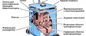
One of the most durable and airtight methods of joining metal parts is electric arc welding. This method has been actively used for more than a hundred years. It consists of melting the edges of the elements being welded and filling the voids between them with the liquid metal of the welding electrode under the influence of an electric current. Initially, bulky power transformers were used for this, reducing the mains voltage to the required 50-60 volts. Nowadays, an inverter welding machine with a modern design and wide technical capabilities is used everywhere.
What it is? Varieties
The general principle of operation of all welding machines is to melt the edges of the workpieces being joined with an electrode, in the process a weld pool is formed. If welding is carried out with a coated electrode or copper-plated wire, then they are also an additive. If a tungsten rod is used, the additive must be supplied manually. Thin sheets can be joined without filler materials.
Simple welding machines consist of a power transformer and a current regulator; inverter circuits involve the use of electronics.
Its purpose:
- Allows you to smoothly regulate the welding current.
- Change the voltage in accordance with other characteristics.
- Maintain stable parameters during welding work.
Modern devices most often use an inverter circuit, the reasons for this are:
- Reduced equipment size – the presence of electronics eliminates the need for large transformers.
- Stable characteristics of the welding arc - the circuit adjusts the parameters during welding.
- Slightly lower requirements for the quality of the electrical network - the inverter circuit consumes less energy.
Expert opinion
Kuznetsov Vasily Stepanovich
The downside is considered to be lower reliability compared to previous generation transformer devices. This applies to all inverters. The second disadvantage is the complex device, which does not allow you to repair equipment without knowledge of electrical circuits.
Craftsmen have learned to restore popular models, but manufacturers do not officially publish schematic diagrams of their welding machines.
For manual arc welding (MAW)
Designed to work with coated electrodes.
Their advantages:
- Simplicity, minimal size and weight.
- Devices that produce a small (up to 190 A) welding current are inexpensive.
- Welding does not require additional materials other than electrodes.
Devices for RDS are the most common and universal. For welding, you will need to purchase coated electrodes, available diameters: 2, 3, 4, 5 mm. Or imported: 2.6 and 3.2 mm.
If the device produces alternating current at the output, then you should purchase electrodes designed for welding with such a device (for example, ANO and similar), and if it is constant, then you can use any: ANO, UCNI, or the like are suitable.
For semi-automatic welding
Welding inverters are suitable for wire welding in carbon dioxide or mixtures.
The advantages of such equipment:
- High welding speed.
- Easy to learn how to work.
- The result is neat seams.
- It is not necessary to beat off the slag crust (it does not form if you use uncoated ordinary wire).
There are also disadvantages: you need to purchase additional equipment. This:
- Gas reducer.
- A hose that can withstand pressure of 2-4 kg/cm.
- Cylinder: volumes of 5, 10, 40 liters are available on sale.
In this regard, it is difficult to carry out welding work in strong winds, carbon dioxide will be blown away, and pores (and other defects) will appear in the seams. Gas will have to be refilled from time to time, and to do this, take the cylinder to the station. Consumption depends on the amount of work and the pressure set on the reducer. Recommended 1-1.5 kg/sq.cm.
Carbon dioxide cylinders are painted gray.
It is possible to cook semi-automatically and without gas, but for this you need to purchase a special cored wire. Sold in small spools of approximately 0.5-0.8 kg. But its cost is almost 2.5 times higher than the price of a regular one including gas.
For argon arc welding (TAW)
The devices are designed for joining non-ferrous alloys: brass, copper, bronze, aluminum, and any others.
The main difference is that the work will require expensive materials:
- Cylinder with gas – argon (Ar+CO2 mixture).
- Non-consumable tungsten electrodes.
- Hose and gas reducer.
- Filler material.
Therefore, the device is worth purchasing if there is an urgent need for welding various alloys. Another unpleasant point: aluminum should be welded with alternating current, while other materials should be welded with direct current. Therefore, you will have to either choose one of the devices, or get a more expensive one - a combined one.
The latter type refers to professional equipment, but manufacturers most often allow RDS mode on such devices. This allows you to save money when connecting steel and cast iron workpieces.
Expert opinion
Kuznetsov Vasily Stepanovich
The last two disadvantages of RAD devices are the difficulty of welding work; it is recommended to practice on thick parts, and you need to learn how to sharpen tungsten correctly.
Operating principle and modes of the inverter source
Transistor inverter source
Transistor inverter source circuit
(Figure 3.10) is most convenient for explaining the inversion process.
The network rectifier unit V
1 converts the alternating voltage of the network into direct voltage, which is smoothed using a low-frequency filter
L
1 -
C
1. Then the rectified voltage
U
sun is converted into single-phase alternating u
of high
1
and
VT 2
.
Next, the voltage is lowered by transformer T to
u
2
,
rectified by a block of valves
V
2
,
passes through a high-frequency filter
L
2 -
C
2 and is supplied to the arc in the form of a smoothed voltage
and
in
.
Figure 3.10 – Schematic diagram (a) and voltage oscillograms (b) of a rectifier with a transistor inverter
Let's take a closer look at the inversion process. When a signal is applied to the base of transistor VT1
its collector circuit is unlocked and current flows through the primary winding of the transformer T in the time interval
t
1 in the direction shown by the thin line.
When the signal is removed from the base, this current stops. With some delay, transistor VT
2 is unlocked, and in the time interval
t
2 the current through the transformer flows in a different direction, shown by the dotted line.
Thus, alternating current flows through the primary winding of the transformer. The duration of its period T and the frequency of the alternating current f = 1 / T
depend on the frequency of the transistors, determined by the control system.
Typically the frequency is set at 1–100 kHz. Since this frequency does not depend on the network frequency, such an inverter is called autonomous. Sometimes an inverter is structurally combined with a transformer T,
a rectifier block
V
2 and a filter
L
2 -
C
1. This device is called a converter; at its output, as at the input, there is a constant voltage, but of a smaller value.
If a powerful storage capacitor (or their battery) is installed at the inverter input C
1, then the inverter voltage
and
1 has a rectangular shape, as shown in Figure 3.10, b.
This design is called an autonomous voltage inverter (AVI). On the contrary, if a powerful inductor L
1 is installed at the inverter input, and the winding of the transformer T is shunted with a capacitor, then the current will be smoothed out. Such a converter is called a current inverter (CIT). Finally, a design is possible in which, due to the presence of inductance and capacitance connected in series, an oscillatory circuit with a sinusoidal current is formed; it is called a resonant inverter (RI).
An inverter is a device that converts direct voltage into high-frequency alternating voltage. Converter is a device for lowering or increasing DC voltage with an intermediate high-frequency link.
Welding mode adjustment
carried out in several ways.
For example, with an increase in the voltage of the network rectifier U
U
also increases, the average value
of U
in the rectified voltage (Figure 3.11, a). For the same purpose, the width of the inverter pulses is changed (Figure 3.11, b). However, a more convenient and common way is to change the pulse frequency (Figure 3.11, c)
The inverter rectifier uses amplitude, width and frequency mode control.
Figure 3.11 – Oscillograms of an inverter rectifier when regulating voltage by changing the amplitude (a), width (b) and frequency (c) of pulses
External characteristics
inverter rectifier depend mainly on the design features of the inverter and transformer (Figure 3.12, a).
The natural external characteristic of the inverter itself is almost rigid (line 1). But since the inductive reactance of the transformer X
T, proportional to the inversion frequency f,
is large
For example, to obtain steeply falling characteristics, negative current feedback
, in which, with an increase in welding current, the inversion frequency decreases, which leads to a decrease in the rectified voltage (line 2):
In a similar way, rectified voltage feedback is introduced to obtain rigid characteristics:
Figure 3.12 – External characteristics of inverter rectifiers
In an inverter rectifier, it is relatively easy to obtain a broken external characteristic (Figure 3.12, b), formed from several sections. Steeply falling section 1 is necessary to set a relatively high open circuit voltage, which is useful when igniting the arc. The flat-sloping main section 2 ensures effective self-regulation during mechanized welding in carbon dioxide. Vertical section 3 limits the welding current, which will prevent burn-through when welding thin metal. The last section 4 sets the value of the short circuit current. Of course, the position of each section is adjusted using separate controls. So, when welding in carbon dioxide, moving the section vertically 2
The welding voltage is regulated, and when welding with coated electrodes, the current strength is set by moving section 3.
The natural external characteristics of the rectifier depend on the design of the inverter and transformer. Artificial characteristics are formed using current and voltage feedback.
The circuit design of a transistor inverter is simpler than that of a thyristor inverter. Of course, this only applies to powerful transistors, when no more than one valve is installed in each arm of the inverter. Previously, Figure 3.10 explained the operation of a push-pull inverter with a zero terminal. The most common circuits in welding rectifiers are shown in Figure 3.13.
Push-pull bridge inverter
shown in Figure 3.13, a.
In the first half-cycle (cycle), the control system starts transistors VT
1 and
VT
4, and the current flows through the primary winding of the transformer in the direction shown by the thin line.
In the second half-cycle, the current path through transistors VT
2 and
VT
3 is shown with a dotted line.
Single-ended half-bridge inverter
in Figure 3.13, b is shown as part of the converter; it has half the number of transistors.
At moment t
1, when transistors
VT
1 and
VT
2 are unlocked, a current pulse, shown by a thin line, flows through the primary winding of the transformer.
This is followed by a pause t
1
-t
4, after which the same current pulse passes in the same direction (Figure 3.13, c).
Thus, in a single-cycle inverter, the current turns out to be variable only in magnitude, but not in direction. The disadvantage of this scheme is significant overvoltages on the transistors at the moment they are turned off. This defect is eliminated by installing diodes VD
1,
VD
2
.
From the moment
t
2 the transistors are turned off, the energy stored in the inductance of the primary circuit returns to the network.
In this case, a current flows through the primary winding through the diodes along the path shown by the dotted line, gradually decreasing by time t
3.
Figure 3.13 – Circuits of transistor inverters
Now let's turn to the processes in the welding chain. Current pulse transformed in the secondary winding from moment t
1 is transmitted to the load through diode
VD
3 along the path shown by the thin line.
From the moment t 2,
the current in the load is maintained mainly due to the energy stored in the inductance L.
For
this purpose, a reverse diode VD
4
,
the current
With a sufficiently large inductance L
the rectified voltage
UB
can be smoothed to a level acceptable under the conditions of the technological process (Figure 3.13, c).
The reliability of a transistor inverter is still low; the most vulnerable element here is the transistors. When designing a welding rectifier, they strive to reduce the number of valves, reduce the current and voltage on them. If the permissible current is insufficient, several parallel-connected transistors must be installed in each arm. In this case, the control system becomes more complicated and the problem of selecting valves with similar characteristics arises. Therefore, it is rational to parallel connect not transistors, but transistor modules, each of which is equipped with its own control and protection elements. In this case, the redundancy principle can be implemented, according to which faulty modules are switched off without compromising the overall performance of the entire rectifier. An example is the MTKD-40-7 module, specially designed for use in key converter circuits. Its maximum collector current is 40 A, and the maximum reverse voltage of the collector-emitter circuit is 700 V. It is a composite transistor with resistors and diodes in the control and protection circuits, its current transfer coefficient can reach 100.
Table 3.1 - Comparative characteristics
small-sized welding inverters
| Model | Manufacturer country | Supply voltage | Power consumption | Welding current range, A | PV, % | Overall dimensions, mm | Weight, kg |
| Master-1600 MLS (Kemppi) | Finland | 4,8 | 10-160 | 410x180x390 | 14,0 | ||
| Minar-140 (Kemppi) | Finland | 4,1 | 10-140 | 305x123x250 | 4,2 | ||
| Invertec V 140-S (Lincoln Electric) | USA | 6,2 | 5-140 | 254x145x350 | 6,0 | ||
| OrigoArc 150 (ESAB) | Sweden | 5,0 | 4-150 | 380x180x300 | 6,9 | ||
| TE 161 (Merkle) | Germany | 3,7 | 3-150 | 290x152x235 | 5,3 | ||
| MOS 138 E (Deka) | Italy | 2,5 | 5-130 | 310x120x160 | 4,0 | ||
| Tecnica 140 (Telwin) | Italy | 4,2 | 5-130 | 315x135x210 | 5,1 | ||
| Technology 150 (Telwin) | Italy | 4,2 | 5-130 | 430x170x290 | 9,2 | ||
| Discovery 140 (Weco) | Italy | 6,9 | 5-140 | 120x310x215 | 4,3 | ||
| Handy S 200 (Lorch) | Germany | 4,5 | 10-140 | 280x138x220 | 4,5 | ||
| S 1601 (Cemont) | Italy | 4,5 | 5-150 | 235x145x340 | 7,7 | ||
| Transpoket 1500 (Fronius) | Austria | 7,0 | 10-150 | 315x110x200 | 4,7 | ||
| Piko 140 (EWM) | Germany | 6,0 | 5-140 | 335x110x220 | 4,5 | ||
| DC 140 ("Technotron") | Russia | 6,9 | 10-140 | 310x120x215 | 4,0 | ||
| Torus-200 (Thor) | Russia | 5,0 | 40-200 | 115x185x280 | 5,0 | ||
| Fast and Furious-125 (GRPZ) | Russia | 4,0 | 40-125 | 330x142x245 | 6,7 | ||
| Progress-130 (“Electric”) | Russia | 5,0 | 3-130 | 367x266x163 | 6,0 | ||
| Adonis-2 ("Kord") | Russia | 5,1 | 35-160 | 165x360x370 | 14,5 | ||
| VDUCH-1371 (“Spetselektromash”) | Russia | 4,0 | 5-130 | 365x140x196 | 8,0 | ||
| VME-120 (“PromEl”) | Russia | 2,7 | 10-120 | 140x240x65 | 2,2 | ||
| VME-140 (“PromEl”) | Russia | 3,2 | 10-140 | 147x250x65 | 2,3 | ||
| VME-160 (“PromEl”) | Russia | 3,7 | 10-160 | 170x296x90 | 3,6 |
The welding properties of inverter rectifiers are significantly better than those of all modern sources, and this is explained by the high speed of the inverter. If other sources have a duration of the transient process that is not less than the period of standard alternating current, i.e. about 0.02 s, then the speed of an inverter rectifier is characterized by values of 0.001 s or less. When mechanized welding in carbon dioxide, the inverter rectifier is capable of providing a complex algorithm for changing the current to control the transfer of electrode metal with a duration of individual cycle stages of about 1 ms. The high dynamic properties of the inverter rectifier are also manifested in the case of program control of the manual arc welding process. In this case, a “hot start” at the beginning of welding, a quick transition from one of the preset modes to another when alternating welding of lower and vertical seams, pulsating arc welding with an adjustable pulse shape, etc. are easily ensured.
The advantages and disadvantages of an inverter source are closely related to each other. Here the energy undergoes at least 4 stages of transformation. Nevertheless, such a rectifier is economical and very promising. The fact is that the core of a high-frequency transformer has a very small cross-section and mass. Typically the core weighs almost 10-20 times less than the core of a 50 Hz transformer. In general, the rectifier also has remarkable mass-energy characteristics: 0.1-0.3 kg per 1 A of welding current and 4-8 kg per 1 kW of power consumption, i.e. weighs 3-5 times less than other rectifiers. And yet, an inverter rectifier is more expensive than other sources, so it is recommended to use it in cases where low weight and dimensions are important - when welding during installation, at home, and during repair work. In operation, such a source is extremely economical. Its efficiency is not lower than 0.7. and sometimes reaches 0.9. The main disadvantage of the inverter rectifier is the excessive complexity of the device and the associated low reliability and maintainability.
The main advantages of inverter sources include:
1. Saving transformer iron metal by 10 or more times compared to a 50 Hz transformer.
2. Good characteristics in terms of mass and energy indicators (0.1...0.2 kg/A, 4..8 kg/kW).
Which device to choose for your home and garden?
The first stage when choosing a device is determining the scope of work. You also need to understand what metals and alloys need to be welded. The second stage is determining the type of food. If 380 V power is available in a country house, workshop or garage, then it is preferable to buy just such a professional device. In this case, the inverter will operate much more stable than from 220 V.
For large volumes, it is better to purchase a semi-automatic machine; with its help, the process of assembling and welding metal structures will speed up by 2-3 times. If you plan to use the device for small jobs, then it is enough to acquire an RDS inverter of 190-250 Amperes. This is enough for welding (channels, angles, fittings) and for cutting steel, if necessary.
Machines for ADS with manual arc welding mode are the most expensive option, but for small workshops they are the best. Allows you to perform work both for yourself and to order.
What else to pay attention to:
- Indication on the panel - will help novice welders set the required welding current.
- Number of settings – will allow you to fine-tune the parameters during operation.
- Load duration (LOD) – how long (in percentage) the inverter will operate within the cycle (5 minutes). This parameter indicates the rated welding current.
- The type of ignition of a tungsten electrode is contact (by touching the part) and non-contact (the electrode is only brought to a distance from the surface). The second type is better - tungsten will last longer and will not stick.
- Stabilization of the welding arc - helps with voltage surges to keep the current at the desired level and prevent the electrode from sticking.
Expert opinion
Kuznetsov Vasily Stepanovich
If the device is purchased for constant work on the road, then you need to pay attention to the weight, dimensions, and length of the welding cables. The duration of the warranty provided by the manufacturer is also important. A number of companies guarantee trouble-free operation for several years.
What do you pay attention to when buying an inverter?
The choice of a welding inverter is based on the welding conditions and the modes to which it must comply. First of all, they are determined by the input voltage. The vast majority of devices are designed for 220 V power supply, but there are also models connected to a 380 V network. In the device passport it is designated as an acceptable range: 220 V + 15% - 30% or 160-240 V. In rural areas with frequent power surges, this can be of great importance.
The most important characteristic of the welding mode is the welding current: it directly depends on the thickness of the parts being welded and the diameter of the electrodes used . In domestic conditions it is rarely necessary to cook products thicker than 10 mm. In this case, it is better to choose an inverter capable of delivering a current of 160-180 A. When welding carbon steel sheets up to 20 mm thick, you should count on 200 A. It is advisable to purchase more powerful units only for specialized workshops. The method of setting is also important. The possibility of smooth control, as opposed to discrete, is always preferable to achieve a high-quality seam.
Advice! When working with thin parts, you should pay attention to the lower limit of the outgoing current, which is preferably at 10 A.
The ease of ignition of the welding arc is related to the open circuit voltage. For most models it is in the range from 40 to 90 volts. The higher this indicator, the easier it will be to cook.
During intensive use, the percentage of operating time at maximum current, designated PV, has a great influence on the performance of the unit. A good device should have this indicator at a level of at least 70%. This means that with a production cycle of 10 minutes, 7 of them can be welded at full load, and 3 minutes should be spent replacing the electrode, cleaning the seam and cooling the device.
Popular models. Reviews
It is necessary to consider several common and proven devices of all three types. It is pointless to study the segment of cheap welders, since buying such inverters is a lottery. They can work for just a week, and sometimes for several years without any problems.
If we talk about manufacturing countries, then you should not be afraid of the inscriptions “Made in China”. The vast majority of welding equipment is manufactured in China. Devices assembled in Europe are almost never supplied to Russia, since due to their excessively high cost there is no demand for them.
For RDS
The three best devices according to ratings from various buyers and sellers.
RESANTA SAI-190
- Maximum welding current – 190 A
- Electrode diameter – up to 5 mm
- Weight – 4.7 kg
- Warranty period – 2 years
Even with unstable mains voltage it cooks well. It is better to use MP-3C 3 mm electrodes. Overheat protection.
Cons : short cables.
Wester MINI 220T
- Maximum welding current – 220 A
- Electrode diameter – up to 5 mm
- Weight – 3 kg
- Warranty period – 60 months
Lightweight and powerful device. Digital display on the front panel.
Cons : no handle for transportation.
Fubag IR 180
- Maximum welding current – 180 A
- Electrode diameter – up to 4 mm
- Weight – 4.6 kg
- Warranty period – 2 years
Convenient carrying handle (there is a belt), reliable body, sufficient power for home and garden use.
Advantages of inverters
A comparison of welding inverters with machines of alternative designs demonstrates the convincing advantages of such equipment.
- Light weight, not exceeding 10 kg, and compact dimensions of most models make them easy to store and transport.
- The absence of heat losses spent on heating the windings has a beneficial effect on the efficiency of the inverter, which, other things being equal, consumes approximately 1.5 times less energy than a typical welding transformer or rectifier.
- The universal inverter has a wide range of output characteristics, which allows you to select modes, including for welding stainless steel and non-ferrous metals.
- Even models for home and garden do not require long breaks in operation to cool the device.
- The welding inverter is equipped with a simple control system with smooth adjustment of all necessary parameters, which allows even a novice welder to achieve high quality welds.
Inverters also have disadvantages, which include a relatively high price and strict requirements for storage and operating conditions. They are sensitive to dust, excess humidity and low temperatures.
How to use and maintain correctly
In order for the equipment to last longer, it is necessary to promptly remove the particles that accumulate inside. To remove it, you must either frequently use a powerful vacuum cleaner, blowing dust out of the ventilation slots, or periodically remove the casing and clean the insides manually - with a brush or compressed air.
Before the end of the warranty period, the bolts securing the body panels cannot be unscrewed.
The semi-automatic burner must be cleaned of splashes during operation. It is recommended to treat the nozzle with non-stick compounds: sprays or paste.
You should not cook at maximum current for a long time, this will lead to a decrease in the service life of the device.
Be sure to follow safety precautions: use a protective mask, mittens or leggings. Do not cook near flammable objects. You should always have fire fighting equipment on hand.
Do you already have an inverter welding machine?
Of course! No, but it will be!
Possible problems
Frequently encountered problems:
- The device turned off during welding - modern boards have temperature sensors that turn off the power. Often an indicator with a graphic symbol “Thermometer” lights up on the panel. In such cases, there is no need to turn off the device. The fan will help cool the inside faster.
- During RDS welding, the electrode sticks all the time - the voltage in the network is low, it is not enough for work. You need to turn off all unnecessary electrical appliances, reduce the current on the inverter, and use electrodes of a smaller diameter.
- When welding with a semi-automatic inverter or ADS, pores appear. Or tungsten does not excite the arc - low gas pressure. It is necessary that a flow of carbon dioxide or argon blows over the welding zone. The optimal pressure is 1-1.5 kg/sq.m. cm. For welding aluminum, sometimes a little more is required.
- There is an electric shock from the body of the device - this often happens outdoors in high humidity. You need to ground the device or work on a rubber mat.
If smoke comes out of the ventilation slots or sparks escape, you need to turn off the power and take the inverter to a service center.
The choice of welding inverter depends on what work will have to be performed in the future.
Examine all possible problems that may arise when working with a welding machine.
Also important:
- Professionalism of the future owner.
- How much money is allocated for the purchase?
- For how long is the device needed?
For frequent and varied work, it is better to buy professional equipment.
Operating principle of a welding inverter
The main difference between an inverter-type welding machine is a more complex chain of transformations to which a standard alternating electric current is subjected with an oscillation period of 50 Hz and a voltage of 220 volts before it is supplied to the electrode. First, it is straightened and smoothed when passing through a special filter. Then rapidly opening and closing transistors invert it into alternating current with an oscillation frequency reaching tens of kHz. Only after this stage the current is transformed to the required 100-200A for welding with a voltage of 50-60V. A high-frequency rectifier operates at the output, achieving the passage of direct current necessary for the highest quality types of welding.
Control and adjustment of the outgoing values of the welding inverter operating parameters is carried out by a transistor control unit. It forms the optimal characteristics of the current supplied to the electrode, necessary for any types and modes of welding.
The main difference between a welding transformer and an inverter is the transformation of low-frequency currents by a power transformer, which is implemented only on large-sized devices, while the high-frequency equipment of the inverter is characterized by compactness and low material consumption.