Home > Tools > Force measuring device
Among the many types of measurements, it is necessary to measure the force of impact, thrust, rotation and others. The device for this is called a dynamometer. This word itself comes from two ancient Greek words: δύναμις - “dynamo (power)” and μέτρεω - “metrio (measure)”.
Dynamometer
What is a dynamometer?
The device determines the relative power of available or required effort to perform any physical action.
Industrial, medical and consumer devices differ:
- dimensions;
- principle of operation;
- calculation method;
- scale type;
- technical parameters and other characteristics.
A dynamometer is used to measure the strength of a person, unit, machine, etc. The designs and types of such devices vary over a wide technical range. In the International System of Units, force is measured in newtons. Dynamometers, depending on their purpose, are equipped with different scales. Some devices measure the force applied in kilograms. It is common European practice to define force in newtons.
It reflects the amount required for 1 second. change the speed of movement of a solid object weighing 1 kg. This indicator is calculated by the computational link of the dynamometer. Most models for household, industrial and medical purposes use decanewtons or kilograms, which is necessary to unify the obtained values. Newtons are used only in some laboratory and educational dynamometers.
Airplane jet engine thrust
The traction force of the engine, or its driving force, is equal to all the forces of air pressure on the internal surface of the power plant. The thrust of some types of jet engines depends on the speed and altitude of the flight. To calculate the thrust of a jet engine, it is often necessary to determine the thrust at a specific altitude, near the ground, during takeoff, and during a particular speed. For a liquid-propellant rocket engine, the thrust force is equivalent to the product of the mass of the outgoing gases and the speed with which they fly out of the engine nozzle.
For a jet engine (air-jet engine), the thrust force is measured as the result of the mass of gases per speed difference, namely the speed of the air stream leaving the engine nozzle and the speed of the air entering the engine. Simply put, this speed is equal to the flight speed of an aircraft with a jet engine. The thrust of a jet engine is usually measured in tons or kilograms. An important qualitative indicator of a jet engine is its specific thrust. For a turbojet engine, thrust related to a specific unit weight of air that passes through the engine per second. This indicator allows you to understand how efficient the air in the engine is to generate thrust. Specific thrust is measured in kilograms of thrust per 1 kg of air consumed per second. In some cases, another indicator is used, which is also called specific thrust, which shows the ratio of the amount of fuel that is consumed to the thrust force per second. Naturally, the higher the specific thrust of a WRD, the smaller the lateral weight and dimensions of the engine itself.
Flight or propulsion power is the force exerted by a jet engine at a specific flight speed. Typically measured in horsepower. The magnitude of the frontal thrust indicates the degree of design optimum of the jet engine. Frontal thrust is the ratio of the largest cross-sectional area to thrust. The frontal thrust is equal to the thrust in kg divided by the area in square meters.
In world aviation, the engine that is most valued is one that has high drag.
The more advanced the WRD is in terms of design, the lower the indicator of its specific weight, namely the total weight of the engine along with instruments and service units, divided by the value of its own thrust.
Jet engines, like thermal engines in general, differ from each other not only in power, weight, thrust and other indicators. When assessing the VFD, a huge role is played by parameters that depend on their own efficiency, namely, efficiency (efficiency factor). Among these indicators, the most important is the remote fuel consumption per specific unit of thrust. It is expressed in kilograms of fuel, which is consumed per hour to produce one kilogram of thrust.
Purpose
Compact devices and stationary equipment have different areas of application. Regardless of the technical modification, dimensions and design of the measuring element, all such devices are designed to determine the applied force.
In construction, a dynamometer is used to measure the degree of pressure on the holding frame:
- vertically suspended load;
- concrete slabs;
- various floors;
- external elements of buildings;
- balconies;
- flights of stairs.
Such large-sized equipment is used in the mining industry to determine the force required to destroy rock using a non-explosive method. In industrial production, stationary dynamometers are used to calculate the strength of materials and structures.
Electronic devices that are used in medicine to determine the physiological parameters of muscle fibers are highly accurate. Such devices measure the power indicators of critical components, mechanisms and assemblies.
Industrial Application
In the metalworking industry, similar equipment is used to determine the functional characteristics of press dies. Dynamometers make it possible to determine with relative accuracy the cutting, bending and deformation forces of metal workpieces and products.
One of the purposes of industrial-type devices is to measure the traction capacity of production plants and torque, which are indicated in the technical data sheet of vehicles, engines and other units.
Dynamometers of different types are used in the manufacture of:
- robotic mechanisms;
- space technology;
- military vehicles and installations;
- prostheses;
- implants;
- heat and electric locomotives;
- electronic and analog scales;
- control and measuring equipment for various purposes;
- power units;
- turbines;
- lifting and rigging devices.
Such devices are used in the production of torque wrenches designed for tightening threaded fasteners with a given force. Dynamometers are needed in the production of agricultural and municipal machinery, mining dump trucks and heavy installation equipment.
In construction
Devices and equipment for measuring force are used in the construction of residential complexes and administrative buildings. They are necessary when designing overpasses and transport interchanges.
Dynamometers are designed to measure the load-bearing capacity of building structures, beams and architectural fragments. Such equipment is used in the construction of dams and other hydraulic structures. They have found application in bridge construction, design of Ferris wheels and amusement rides.
In medicine
Any physiological and anatomical parameter of the human body can be accurately assessed in digital terms. For this purpose, specialized medical devices are used.
The dynamometer is used to measure muscle strength and muscle contractions. Devices for medical purposes have a wrist or postural design. There are optical dynamometers that are used to determine the strength of the muscle fibers that support the eye lens.
The use of such monitoring and measuring equipment for medical purposes allows you to accurately:
- Establish the patient's physical condition.
- Determine the speed of recovery after exhaustion, serious illness or injury.
- Assess the dynamics of postoperative rehabilitation.
- Calculate muscle functionality.
- To find out the degree of muscle development in patients with birth defects and genetic pathologies.
Indicators of muscle strength provided by a medical dynamometer vary within a certain range depending on the degree of fatigue of the subject, his age, and gender. Using a dynamometer, the strength of the handshake is determined, which, according to recent scientific data, can be used to determine the functional state of the heart apparatus and predict the risk of an acute cardiac crisis.
An important medical purpose of the device is to assess children's health. Scientists from Baylor University (Texas, USA) found that the functional state of a child’s body can be determined by the strength of the hand’s grip. There is evidence of a relationship between muscle weakness and life expectancy. To determine this parameter, such a measuring device is used.
Vibration analyzer
The most commonly used measuring instruments are computer-based: shape analyzers, spectral analyzers and envelope spectrum analyzers, the structure of which is shown in figures , , . The functions of the shape analyzer () are to measure the amplitudes and phases of individual signal components and to comparatively analyze the shape of individual signal sections, the beginning and end of which is determined by the angle of rotation of the shaft. Such analyzers are widely used for diagnosing reciprocating machines and rotors during the balancing process. The spectrum analyzer () thanks to the use of the same type of elements allows you to reduce the processing time of the vibration signal. The introduction of an envelope detector into the circuit makes it possible to detect damage to rolling bearings and elements of the mechanical system at the early stages of its inception ().
Figure 89 – Structure of vibration and noise waveform analyzer
Figure 90 – Structure of the spectrum analyzer for vibration and noise signals
Figure 91 – Structure of a spectrum analyzer with an envelope detector
Analyzers are produced that implement the capabilities of personal computers, the structure of which is shown on. Such instruments for measuring and analyzing signals are large in size and are used in laboratory or bench conditions.
Figure 92 – Structure of the input device (ADC - analog-to-digital converter)
The development of the design of vibration analyzers is inextricably linked with the development of computer technology. Reducing dimensions, increasing memory capacity and functions are the main directions of development of spectrum analyzers.
Types of dynamometers
In accordance with the design of the power unit and the implemented operating principle, electronic, hydraulic and mechanical devices are distinguished. The latter are further divided into spring and lever. There are combined models that combine several operating principles to ensure high accuracy of measurements for various purposes. A special category of dynamometers are diagnostic devices that have their own classification.
Some models are intended exclusively for use in medical institutions, hospitals and physiotherapy offices. There are compact household dynamometers.
The range of such devices is varied and includes dozens of manual options. There are specific devices for single use, called disposable sensors.
They are used to determine the strength of destructive loads - powerful explosions, extreme dynamic pressure, colossal impacts. Before losing integrity and failing, they manage to transmit a signal to a receiving unit located at a safe distance about the characteristics of the destructive impact.
Mechanical models
The simplest and most unpretentious products to use. In a spring-type mechanical dynamometer, the applied force is transferred to a spirally twisted steel wire. Depending on the design features and purpose of the device, the working element is subjected to tension or compression. The recorded indicator of elastic deformation is recorded by the arrow of the measuring scale. The result is considered proportional to the mechanical force.
Dynamometers with a lever instead of a spring are no less common. It is attached to the needle of the measuring scale. The acting force deflects the lever rod or plate by a certain number of units. The recorded value is considered to be indicative of the applied mechanical pressure. Such dynamometers cannot be called very precise measuring instruments.
The simplest and well-known stretching instrument is the cantar or steelyard. This is a manual scale with a spring design. A common example of a lever tool for household use is a torque wrench for cars.
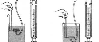
Hydraulic modifications
Devices of this type measure the force of an external influence by moving (pushing) a liquid contained in a special flask. The displaced substance moves through the pipe onto a scale that records its level. A dynamometer is used to measure torque in turboprop engines. Hydraulic models are installed in aircraft equipment for automated feathering of the propeller in the event of a power plant failure.
Such devices are much more accurate than their mechanical counterparts, but have a more complex design. Depressurization of the cylinder with liquid instantly leads to loss of functionality of the device.
Errors in dosage when filling a hydraulic dynamometer have a significant impact on the performance of the device and the accuracy of calculations. In aviation technology, devices are used that are made in the form of several cylinders from a high-strength and heat-resistant composite or metal alloy.
Electronic dynamometers
The design contains a pair of sensors for different purposes. One, considered the main one, converts deformation energy into an electrical impulse. An auxiliary sensor is needed to amplify the signal and record it in RAM.
The electronic unit is:
- inductive;
- piezoelectric;
- vibration-frequency;
- capacitor;
- strain gauge.
Such devices are extremely accurate and maintain synchronization with additional equipment - mechanisms for determining cutting force or wire devices that are used to evaluate resistance. Electronic dynamometers are equipped with a small display and a touch or keypad control panel. The calculated result is displayed as a numerical value and in the form of an oscillogram.
Reference models
This category includes electronic devices with particularly precise calibration. They are used in laboratory practice, for setting up other dynamometers, and on test benches. Reference devices are designed for testing critical components, assemblies and mechanisms. This dynamometer has a force sensor connected to a digital measuring unit. The performance of exemplary models is not affected by environmental conditions.
They are equipped with an integrated self-diagnosis mechanism. Such devices have the function of automatically compensating for lateral loads, preventing them from distorting the value displayed on the display. The dynamometer, which is given the name reference, is used to measure strength indicators with maximum accuracy. Such devices have compact dimensions, resistance to external factors and durability.
They have a user interface, a variety of digital indicators and a port for connecting to a computer. Reference models are compatible with other types of control and measuring equipment, which allows for a comprehensive assessment of the operating parameters of the tested mechanisms and products.
Medical dynamometers
Highly specialized devices designed to test the physiological parameters of the body, performance and endurance of people. Such dynamometers are used in clinical practice and sports medicine. Existing models are wrist and backbone. The former are diagnostic devices for determining the compressive capacity of the upper limbs.
Devices of this class are used to assess the condition or monitor professional suitability in:
- physiotherapy practice;
- sports;
- Ministry of Emergency Situations;
- military units;
- law enforcement agencies;
- companies providing forwarding services;
- transport enterprises.
A separate group consists of children's hand dynamometers. The most common domestic model in this category is DMER-30-0.5. Milling devices have great functionality. They are intended to test the strength of different muscle groups responsible for straightening the body, maintaining balance and stabilizing the spinal column. The most popular model of deadlift dynamometers is DS-500.
Torque measurement using angular rotation sensors
There is another way. It is not new, but it seems to have been successfully forgotten. This option was first used in the 50s of the last century to measure torque in internal combustion engines - most clearly in the turbojet engines of heavy cargo aircraft Hercules and C-130. The technicians measured the amount of twist, and therefore the torque, by measuring the amount of phase shift between two multi-period resolvers mounted and aligned on the shaft. The term "multi-period" refers to the output of the resolver - so a two-period resolver has a cyclic output signal that determines the absolute position with an accuracy of 180°; The 36-period resolver has a cyclic output signal that determines the absolute position with an accuracy of 10°.
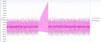
When the shaft rotates, each of the resolvers produces two signals: the first changes according to a sinusoidal law, the second - according to a cosine law. For simplicity, Figure 1 below shows only two demodulated sine waves.
Figure 1 — Torque measurement using multi-period resolvers.
When zero torque is applied, the signals from both resolvers are identical and have no phase shift. In the case when a real torque is applied to the shaft, the signal of one resolver has a phase shift relative to the signal of the other resolver. The magnitude of this phase shift is directly proportional to the applied torque. Using multi-period resolvers with a large number of cycles (for example, 128), it is possible, even with a small amount of twist, to obtain a response in the form of a relatively large amount of phase shift. In other words, this technique is precise enough to measure shaft torsion not only at levels less than 1°, but even at levels less than 0.1°. From which it follows that the shaft on which the measurement is made does not have to be long. Indeed, the shaft length required for successful measurements may be less than 25 mm. This can be achieved by using a deliberately flexible shaft or by placing the resolvers concentrically - one inside the other - and connecting the outer and inner parts of the shaft using a spring of increased torsional rigidity.
Unlike strain gauges, resolvers are known for their reliability, robustness, and accuracy, and are often used in aerospace, defense, and oil and gas applications where high accuracy and ruggedness are required. Because the resolver is a non-contact measuring device, it also eliminates the need for current collectors or RF transmission equipment.
So why has this measurement technique become unfashionable? Probably one of the reasons is that resolvers themselves have lost their popularity. Plane-parallel and flat-plate resolvers with a large hollow shaft, ideal for use in torque measurements, are downright expensive. Moreover, the combination of resolver motors with control electronics can be very complex. Since nowadays engineers are more accustomed to digital electronics, they are very reluctant to deal with analog electronics themselves and, even more so, with measuring the phase shifts of analog variable signals.
Why is it necessary to know strength indicators?
Such devices have virtually unlimited applications. Manufacturers of various equipment indicate the results obtained with their help in technical documentation. Measuring power and load capabilities allows you to predict the service life and determine the operational life of a machine, component or unit. On this basis, rules for the use of products and their service are established.
The data obtained using dynamometers is used in engineering calculations and design work. Such information is of key importance during the construction of buildings and bridges, hydraulic engineering and other structures. Using established strength indicators and load capacities, they ensure the safety of road traffic, manned flights, operation of mechanisms and equipment, and park attractions.
In medicine, data obtained using such devices is necessary for choosing therapeutic tactics, methods and means of rehabilitation. For professional athletes, dynamometer analysis allows them to evaluate the effectiveness of training and make the necessary adjustments to accelerate progress.
Methods for mounting vibration sensors
The following methods of attaching vibration sensors ():
- using a hairpin;
- adhesive joints, including fastening with beeswax;
- use of intermediate elements;
- using magnets;
- using a probe.
Figure 82 – Methods of mounting vibration sensors
Stud mounting on a smooth, flat surface is preferred. The measurement site is pre-prepared (). A hole is drilled, a thread is cut, and the surface is polished. The following requirements are met:
- the depth of the threaded hole must be sufficient so that the pin does not rest against the bottom of the hole in the base of the sensor;
- surface roughness no more than 1.6...0.25 Rz;
- non-perpendicularity of the axis of the threaded connection to the plane of fastening of the converter is not more than 0.02%;
- non-flatness of the mounting surface 0.01%;
- torque when attaching the sensor to the M4...M8 stud is 1.7...2 Nm.
Figure 83 – Requirements for the installation location of the sensor using a stud
The surface of the object must be smooth and clean. A layer of grease is applied to the working surface of the sensor, which increases the rigidity of the mechanical connection between the sensor and the measurement object and creates good contact between the surfaces.
The amplitude-frequency response of a piezoelectric sensor mounted with a steel pin on a smooth surface of an object is shown. In this case, the resonant frequency of the piezoelectric sensor is almost identical to the resonant frequency obtained during calibration by the manufacturer (approximately 33 kHz).
Disadvantages: a lot of time is spent on installing the sensor and the need for plumbing work.
An alternative method of attaching piezo sensors is to attach them to a thin layer of beeswax, using glue, cement, and others. The resonant frequency decreases slightly (). This fastening method is applicable at room temperature of the object’s surface and low vibration amplitude.
The disadvantages of this fastening method are the softening of wax or glue with increasing temperature (permissible temperature +35...40 ° C) and the unreliability of fastening massive sensors, especially in a measurement direction other than vertical. Mounting the sensor with beeswax on a smooth, clean surface when measuring vibration in the vertical direction can be considered acceptable for sensors weighing no more than 20 g with vibration acceleration amplitudes of up to 100 m/s2.
The use of intermediate elements - plates, disks - leads to distortion of the perceived signal at high levels due to mechanical filtering and a decrease in the resonant frequency due to the increased compliance of the system.
In cases where it is necessary to ensure strong fastening of the accelerometer without disturbing the surface of the object with threaded holes, special pins are used, fixed to a flat disk (intermediate elements) attached with hard glue or cement. Epoxy resins and cyanoacrylic adhesives are recommended as gluing materials. An insulated pin and mica washer are used where electrical isolation of the accelerometer from the object is required.
The most widely used method is to attach sensors to a smooth surface of an object using a permanent magnet. In this case, the static force of adhesion of the magnet to the measuring surface largely affects the measurement range. This determines the need to use neodymium magnets with a force of 30...50 N. The requirements for surface treatment are the same as for connections using a pin. Magnetic mounting () reduces the measured frequency range to 5000 Hz. The resonant frequency in this case decreases to approximately 7 ... 15 kHz and depends on the type of magnet.
Figure 86 – Amplitude-frequency response of a vibration sensor when attached with a magnet
Vibration measurement using a probe, reduces the upper frequency range () to 1000 Hz. The angle between the measuring axis of the vibration sensor and the measuring direction must not exceed 25°.
Factors that influence strength performance
Electronic devices are considered the most accurate. Their measurements are virtually unaffected by environmental factors. The results of medical examinations are influenced by the time of day and the patient’s physical fitness. The lowest muscle strength is recorded in the morning and evening hours. At midday, this physiological indicator reaches its peak value.
The amount of muscle strength is affected by the psycho-emotional state at the time of the test. Sleep disorder, nutrient deficiency in the body, vitamin and oxygen starvation reduce muscle activity and reduce the indicators obtained by measuring with such a device. Mechanical dynamometers are considered the least accurate.
The level of error in calculations of such devices is influenced by a large number of external and design factors:
- ambient temperature;
- air humidity and density;
- degree of wear of parts;
- backlashes;
- build quality;
- power block manufacturing material;
- spring properties of steel, which change during operation.
A dynamometer is used to measure the strength capabilities of a mechanism, building structure or human body. In the latter case, the obtained values decrease with insufficient physical activity and muscular dystrophy.
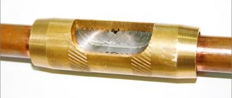
Description of KINGTONY 34855 devices
The presented dynamometer is made with two holders. The spring in this case is used with great strength. The dial is applied with 0.2 mN divisions. The overload protection system is first class. The case is of a moisture-resistant type. The maximum overload allowed is 13 N.
Fastening for installation is included as standard. If you believe customer reviews, this dynamometer is not afraid of sub-zero temperatures. The measurement accuracy of the device is at 0.6%. The modification is not best suited for laboratory experiments. You can buy these devices for measuring force for 65 thousand rubles.
Operating principle of a dynamometer
Mechanical models are considered the simplest in design and operating principle. In spring modifications, a force to be measured is applied to the elastic part. It causes deformation changes - stretching or compression. This activates a pointer attached to the spring, which moves along the scale, recording the amount of force applied. Lever and hydraulic dynamometers have a similar operating principle.
In the latter, the role of a deformable element and, at the same time, a recording device is played by a liquid pushed out by the applied force. In lever models, a moving part changes position under external pressure. The lever moves the arrow attached to it by a certain number of scale divisions. Due to their accuracy and versatility, strain gauge devices have become widespread.
Such devices are capable of recording dynamic and static loads. Its design includes a measuring element of increased elasticity and several strain gauge grids. The applied force causes deformation changes, which lead to an imbalance of the resistance bridge currents. As a result, an electrical impulse is generated, captured by a special sensor and displayed on the display as a digital value.
Induction models, designed for testing power units with power up to 966 hp, are distinguished by a fundamentally different mechanism of action and low inertia. The design of such devices includes a polished metal disk that is influenced by electromagnetic forces. It turns around at a set speed, generating current vortices, the magnitude of which is recorded by a tensor sensor.
The dynamometer is used to measure static load indicators. For this purpose, devices with a piezoelectric operating principle are used. The structural structure of such devices includes a special plate.
It is based on quartz with defect-free areas. The mineral has a direct or inverse piezoelectric effect. A charge is formed by mechanical action on a quartz plate. The type of electrical reaction is determined by the position of the cut relative to the axial lines of the crystals. A special converter transforms the charge into voltage. Devices of this class are used to assess the impact power.
To measure pressure during grinding, milling and other types of metalworking, control tools with a wire indicator are used. Their design includes a square plate made of a durable and elastic alloy. It is attached to the inner surface of the case with spring links made of a special grade of steel. The device allows you to measure horizontal and radial force with high accuracy.
The pressure exerted on the plate is recorded by the reading unit, which displays it on the display. The sensor accurately captures the vibration pattern of the part on the elastic fasteners and converts them into digital values.
Hydraulic devices
Hydraulic dynamometers have many advantages. First of all, it is important to note the simplicity of the design. The hydraulic mechanism is located under the handle on models. Holders are often used in a curved shape. These devices are well suited for hospitals. However, they are rarely used for laboratory experiments. First of all, it is important to note that they are afraid of high temperatures. The maximum load parameter is on average 4.5 N. At high humidity, hydraulic devices should not be used.
Specifications
They depend on the type, functionality and scope of application of the device. The most common domestic models of dynamometers are the DK series.
These simple, but accurate and reliable mechanical devices have the following technical characteristics:
| Parameter | Meaning |
| Calculation range | 3-140 decanewtons (daN) |
| Level of error | 0.75-4 daN |
| Scale pitch | 0.5-2 daN |
| Weight | 170-250 g |
Electronic copies are more diverse and functional. They have an extended range of measured indicators - 2-120 decanewtons. The discreteness (level of error) for most of these devices does not exceed 0.5 daN. Electronic dynamometers automatically turn off after a time specified in the settings if there is no user activity. They can withstand temperatures of +10...+35°C without errors in calculations.
Medical diagnostic equipment of the stand type has a maximum value of up to 500 decanewtons. Such devices are equipped with a large scale with a division value of 2-5 daN. Such devices make it possible to diagnose early manifestations of scoliosis and postural disorders in children.
How to avoid getting injured when taking measurements?
To be on the safe side, if in doubt, it is better to read the instructions for the electrical appliance and check that the connection is correct.
When taking measurements, it is important to remember about protective measures when working with electric current. Injury can occur even when working with low-current devices.
Especially in conditions with high humidity. It is necessary to work in rubberized overalls.
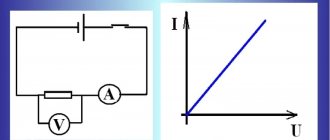
To study ST, scientists came up with measuring electrical devices. Due to the low internal resistance, these meters do not affect the parameters of the electric current in the measured current circuit. The devices are actively used at industrial sites and at home.
Dynamometer in everyday life
With a steelyard you can quickly measure the weight of hand luggage, household items and food products. Despite the advent of high-precision electronic scales, cheap and convenient pocket dynamometers are still actively used in everyday life.
More structurally complex devices in everyday life are used to measure the force of closing elevator doors and passenger transport:
- buses;
- trolleybuses;
- trams;
- subway cars.
There are home instruments designed to assess the degree of ripeness of fruits. The operation of the tonometer is based on the dynamometer principle. Such a device will be needed if it is necessary to find out the weight of substances in different states - liquid, bulk, dry.
Dynamometers are useful when performing installation and construction work and apartment renovation. They are used to evaluate the lifting force of car windows. Mechanical devices are used in everyday life to measure the closing force of hatches and sliding garage doors.
Description of DK-158 devices
This is a professional and multifunctional dynamometer. The model is not the best for measuring grip strength. It supports all major units of measurement. If desired, the software can be changed. The interface is provided by the manufacturer for the C203 series. In total, the dynamometer of this series uses three adapters. The device does not support memory cards. The first class overload protection system is used. If desired, you can connect scales. The switching speed is 1.3 seconds.
The graphic display is provided with bright backlight. There is a function for saving measurement results. The battery used to operate the device is lithium type. Its conductivity parameter is 3.3 microns. The battery life is a maximum of 12 hours. If necessary, the dynamometer can be put into sleep mode to save battery power. These devices for measuring force cost about 46 thousand rubles.
How is this device developing today?
Modern industry does not stop there. The appearance of such devices in people's lives has made it possible to create many useful devices that make life easier. Manufacturers use new discoveries and new technologies in their work. Gradually, old models are falling out of use and new, more convenient ones are appearing. So, today, instead of the usual mechanical ones, electronic force meters are increasingly used. They differ in their constituent elements.
The device of electronic devices contains a strain gauge, that is, a force sensor, measuring indicators and connecting wires or radio channels. The operating principle of this type of device is based on measuring deformations with a strain gauge sensor due to the influence of applied forces. During operation, an electrical signal is generated that is completely directly proportional to the reported deformation. The resulting indicators are power quantities.
Currently, these devices are used in many industrial sectors for calibrating testing machines or stands. Therefore, manufacturers are trying to produce more often such devices, the purpose of which is to determine not only changing, but also static tensile and compressive forces. The latest model of the measuring device SIU2 and SIU works precisely using the compression tool. Their use is most in demand at enterprises where it is necessary to inspect test structures.
Basic connection diagrams
Let's consider this using the example of connecting strain gauges to household or industrial scales. A standard strain gauge for scales has four multi-colored wires: two inputs are power (+Ex, -Ex), the other two are measuring outputs (+Sig, -Sig). There are also options with five wires, where the additional wire serves as a shield for all the others. The essence of the operation of a beam-type load cell is quite simple. Power is supplied to the inputs, and voltage is removed from the outputs. The magnitude of the voltage depends on the applied load on the measuring sensor.
If the length of the wires from the load cell to the ADC unit is significant, then the resistance of the wires themselves will affect the scale reading. In this case, it is advisable to add a feedback circuit that compensates for the voltage drop by correcting the error from the wire resistance introduced into the measuring circuit. In this case, the connection diagram will have three pairs of wires: power supply, measurement and loss compensation.
Vibrometers
The block diagram shown in Figure 88 illustrates the design and operating principle of a modern vibrometer. The accelerometer is connected to a charge amplifier, which forms the input stage of the device. The charge amplifier in the input stage eliminates the need for an external preamplifier and makes it possible to connect the accelerometer and vibration meter with a long cable without a noticeable loss of system sensitivity.
Figure 88 – Vibrometer block diagram
A cascade of electronic integrators provides measurement of vibration velocity and vibration displacement. High- and low-pass filters are adjusted according to the requirements for the width of the analyzed frequency band and the operating frequency range of the accelerometer used. Filters allow you to effectively suppress interference caused by low- and high-frequency noise. The amplifier stage provides the necessary signal amplification.
The vibrometer allows you to measure the root mean square, peak, or peak-to-peak value of the measured signal. The design may include a storage device. The storage device is effective in measuring mechanical shocks and transients. After conversion in the linear-logarithmic converter stage, the measured signal is supplied to the measuring device.
Together with the vibrometer, you can use external filters that provide frequency analysis of the mechanical vibrations under study. The vibrometer is equipped with AC and DC voltage outputs. This allows you to connect oscilloscopes, measuring tape recorders and recording instruments. The dynamic range determines the ability of vibration measuring equipment to maintain a linear relationship between input and output when measuring the amplitude of a vibration signal. Expressed in dB or vibration parameters.
The dynamic range is limited from above by the maximum value of the input charge, and from below by the self-noise level of the charge amplifier. Dynamic range depends on the accelerometer conversion factor.
The value of the signal-to-noise ratio (Ksh) is regulated by GOST 30296-95:
- for the frequency range 10 Hz Ksh = 2.51;
- for the frequency range from 10 Hz and above Ksh = 3.162.
The dynamic range of vibration diagnostic equipment lies in the range of 60...100 dB, sometimes higher.
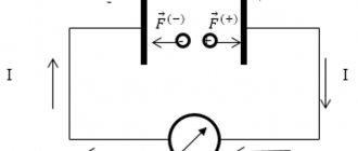
Operating principle and scope of application
The unique structure of the device allows it to function according to a simple communication scheme. Along with a permanent magnet, a steel armature and an arrow attached to it are located on the axis of the bracket. When exposed to an armature, permanent magnets transfer their properties to it. In this case, the position of the armature is located along the field line passing near the magnet.
This position of the anchor sets the zero mark of the needle on a graduated scale. Magnetic flux occurs when current from a generator or similar source flows through a bus. A right angle is maintained between the magnetic field lines and the armature location point. The power level of interaction between the flows will depend on the magnitude and direction of the electric current flowing through the bus. It is by this indicator that the instrument needle deviates from zero.
The unit is widely used in the following industries:
- radio electronics;
- electrical engineering;
- energy branch of industry;
- construction;
- transport networks;
- research laboratories.