Why is grounding needed?
Complex modern equipment is energy-dependent - not only pumping stations, washing machines and dishwashers, microwave ovens and electric boilers, but also any gas boiler is stuffed to the brim with electronics. Coupled with a host of useful functions and undeniable convenience, all of these devices are potentially dangerous. No one gives a 100% guarantee that a breakdown will happen at one far from perfect moment. Those who took care of effective grounding will not feel anything, the RCD will simply trip, but for those who did not take the problem seriously, it is unlikely that everything will end only in repairing equipment, and it is much more difficult to repair a person. Grounding is the most important protective system that works in several directions:
- Prevention of electric shock through the housing of electrical appliances or elements of engineering communications in the event of malfunctions;
- Ensuring optimal operating conditions and protecting expensive equipment and household appliances;
- Organization of lightning protection.
Gennady ChebatarevTechnical specialist at OBO Bettermann
As a rule, we pay insufficient attention to the problem of grounding an object. Grounding is not common, although it is a mandatory event. According to PUE 1.7.101, for electrical equipment 220-380 V, a grounding conductor with a resistance of no more than 30 Ohms is required! The grounding system protects a person from touch voltage as a result of a breakdown of an electrical appliance and discharges dangerous potential into the ground through a grounding source. Also, when operating gas boilers, it is necessary to maintain a resistance of the grounding system of no more than 10 Ohms! If this value is exceeded or there is no grounding system at all, then the gas equipment will not work properly or not work at all!
Circuit design
Components
The previously mentioned grounding resistance (Rз) of the circuit is the main parameter controlled at all stages of its operation and determines the effectiveness of its use. This value must be so small as to provide a free path for the emergency current tending to flow into the ground.
Note! The most important factor that has a decisive influence on the value of grounding resistance is the quality and condition of the soil at the site of the installation. Based on this, the charger in question or the ground loop of the charge circuit (which in our case is the same thing) must have a design that meets the following requirements:
Based on this, the charger in question or the ground loop of the charge circuit (which in our case is the same thing) must have a design that meets the following requirements:
- It must include a set of metal rods or pins with a length of at least 2 meters and a diameter of 10 to 25 millimeters;
- They are connected to each other (necessarily for welding) by plates of the same metal into a structure of a certain shape, forming a so-called “grounding conductor”;
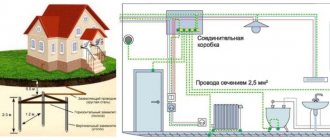
- In addition, the device includes a supply copper busbar (also called electrical) with a cross-section determined by the type of equipment being protected and the magnitude of the drain current (see the table in the figure below).
These component devices are necessary to connect the elements of the protected equipment with the descent (copper busbar).
Differences in device location
According to the provisions of the PUE, the protective circuit can have both external and internal design, and each of them is subject to special requirements. The latter establishes not only the permissible resistance of the ground loop, but also stipulates the conditions for measuring this parameter in each particular case (outside and inside the object).
When dividing grounding systems according to their location, it should be remembered that only for external structures the question of how the grounding resistance is normalized is correct, since it is usually absent indoors. Internal structures are characterized by wiring of electrical busbars along the entire perimeter of the premises, to which grounded parts of equipment and devices are connected through flexible copper conductors.
For structural elements grounded outside the facility, the concept of re-grounding resistance is introduced, which appeared as a result of the special organization of protection at the substation. The fact is that when forming a neutral protective conductor or a working conductor combined with it at the supply station, the neutral point of the equipment (step-down transformer, in particular) is already grounded once.
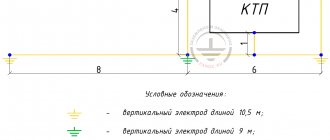
Therefore, when another local grounding is made at the opposite end of the same wire (usually a PEN or PE bus connected directly to the consumer panel), it can rightfully be called repeated. The organization of this type of protection is shown in the figure below.
Important! The presence of local or repeated grounding allows you to insure yourself in case of damage to the protective neutral wire PEN (PE - in the TN-CS power supply system). Such a malfunction is usually found in technical literature under the name “zero burnout”
Such a malfunction is usually found in technical literature under the name “zero burnout.”
Why is reinforcement not suitable as a grounding conductor?
One of the widespread methods of grounding a private house is modular-pin, using conventional reinforcing rods. But also according to GOST R 50571.5.54-2013/IEC 60364-5-54:2011 Low-voltage electrical installations, introduced on January 1, 2015, and according to GOST 58882-2020, which entered into force on January 1, 2022, “Grounding devices. Potential equalization systems. Grounding electrodes. Grounding conductors", steel is not suitable for these purposes. For electrical installations with voltages up to 1 kV, the grounding system can only be made from corrosion-resistant materials:
- stainless steel;
- galvanized steel (hot-dip galvanizing or electrolytic coating, with a minimum zinc layer thickness of 1 micron);
- copper plated steel (minimum 70 microns radial copper coating with 99.9% copper content);
- copper.
Considering our attitude to various standards, even from professionals, not to mention self-builders, when choosing a material for grounding conductors, it is worth starting from expediency. Yes, fittings are available and even now, when they have risen in price several times, the costs will be minimal. However, grounding is not arranged for a year, not for five, and not even for ten or twenty - ideally, forever. In the foundation, the reinforcement cage is protected by a layer of concrete, which prevents direct contact with moisture; in the ground, the steel is not protected by anything and is unlikely to last even a decade. Whereas a specialized kit will last much longer.
Gennady ChebatarevTechnical specialist at OBO Bettermann
According to GOST R 50571.5.54-2013/IEC 60364-5-54:2011, part 5-54 “Grounding devices, protective conductors and protective potential equalization conductors”, ferrous metal cannot be used for grounding. And most importantly, ferrous metal will rot in the ground in 2-5 years. The service life of the OBO Bettermann grounding kit is up to 50 years! Installation of a special grounding conductor guarantees good grounding characteristics.
Clutchless rods
By the way, despite all the advantages and good contact, many consider threaded connections to be the weakest point of such modular systems.
Think about water pipes lying in the ground. After several years of operation, it is the threaded couplings that rust first.
The same thing can happen with pins. In addition, at the moment of hammering with a vibrating hammer, the connection often weakens. Simply put, the thread is unscrewed.
Experienced installers, after each entry of another rod into the ground, tighten the electrode along the thread. At this point another mistake occurs.
When you tighten a smooth pin or socket with a serrated wrench, you scratch and strip the copper layer from the surface. What this leads to was discussed above.
After 3-4 years, instead of a full-fledged electrode, you will be left with a hollow copper tube with rusty dust inside.
This way you will not touch either the electrode or the coupling.
Also note that in all coupling kits, the coupling itself is slightly wider than the diameter of the rod. What does this mean? A narrower electrode, when entering the ground following such a coupling, will not be in close enough contact with the soil surface
To obtain real resistance indicators, sometimes you have to wait several days until the earth crumbles and compacts all the free spaces
A narrower electrode, when entering the ground following such a coupling, will not be in close enough contact with the soil surface. To obtain real resistance indicators, sometimes you have to wait several days until the earth crumbles and compacts all the free spaces.
Therefore, many people prefer a different type of deep grounding rods. For example, like OBO Bettermann with the BP (Bundes Post) system.
In such sets, the pins are joined together without threads, using the pressing method.
This is something like a tongue-and-groove connection with a self-release pin. When driven in, the tenon is tightly wedged into the groove and an absolutely monolithic connection is obtained.
Sometimes inside the hole at the end of one rod there may be a lead ball, which, when struck, fills the entire space even more tightly.
Therefore, if you do not trust couplings and want to eliminate the human factor, buy such kits.
How to make an effective grounding system
There are several ways to organize grounding, dozens of specialized topics, on hundreds of pages, which often only complicates the choice. This is where these typical questions arise.
mikle77FORUMHOUSE member
Tell me, who knows how to properly ground a house? Some say that you need to bury a metal strip and weld it to the reinforcement of the foundation strip, others say that you don’t need to weld anything... But how to do it correctly?
Gennady ChebatarevTechnical specialist at OBO Bettermann
Grounding can be done in several ways:
- A ring grounding conductor, usually in the form of a 40x4 mm strip or 10 mm wire, is laid in a trench 0.5-0.7 meters deep, at a distance of 1 meter from the foundation of the building. Additionally, it is equipped with vertical rods to ensure good grounding resistance. Preferably no more than 10 ohms.
- Fundamental grounding. This is done when pouring the foundation by laying a strip on a chain-link and with the obligatory connection of reinforcement (every 5 m according to GOST R 58882-2020)
Conclusion: If you connect the foundation to the ground electrode, then the foundation must have reliable electrical contact over the entire area. The connection is usually made by bolting. The use of welding entails a violation of the protective layer of the conductor (zinc) and is the site of corrosion and an increase in contact resistance.
For private housing construction, we recommend using a ready-made grounding kit, with which you can organize a high-quality grounding center at one point.
Foundation grounding has its own difficulties.
vova3232FORUMHOUSE Member
How to weld a strip to the foundation if the foundation is made of reinforced concrete, and according to the rules for constructing such foundations, the reinforcement should not protrude from the concrete so as not to rust?
Gennady ChebatarevTechnical specialist at OBO Bettermann
Connections between strip and reinforcement can be made with special OBO Bettermann reinforcement connectors, for example 5313015-259 A-FT, which can connect conductors with a diameter of up to 22 mm and a strip with a width of up to 50 mm. The connection occurs before pouring concrete. If the foundation is already ready, we recommend making a ring grounding or using deep grounding electrodes.
In the case of a grounding device, the most important thing is the result - resistance.
GrinyaForumHouse Member
I'm reading how to make grounding. There is an idea to drive 2 m pins or corners around the perimeter of the house (can’t hammer in any more, there is a 2.4 m layer of limestone) with a distance of 2-3 m. And weld all these pins to the tape around the perimeter of the house. The house is approximately 13x11 m. So I’m thinking - won’t it be excessive? The house is aerated concrete with floor slabs. It will be like grounding and SUP.
Gennady ChebatarevTechnical specialist at OBO Bettermann
The main indicator of whether grounding is sufficient or not is measuring the grounding loop using a special verified instrument (for example, Sonel MRU-101, TE-30). According to PUE 1.7.101, for electrical equipment 220-380 V, a grounding conductor with a resistance of no more than 30 Ohms is required, and according to the new GOST R 58882-2020 clause 7.7.3.7 The resistance of the charger according to GOST R IEC 62305-4 must be less than 10 Ohms (measured at low frequency).
If you use 2 m vertical grounding conductors, then the distance between these grounding conductors should be 2 m or more, according to SO-153 “Instructions for the installation of lightning protection of buildings, structures and industrial communications” Clause 3.2.3. Grounding electrodes. Grounding electrodes must be located at a depth of at least 0.5 m outside the protected object and be as evenly distributed as possible; At the same time, we must strive to minimize their mutual shielding.
Connection diagrams
The most popular grounding connection schemes are:
Closed, in the shape of a triangle (Fig. 3). The main advantage is more stable and reliable operation. If the jumper between the rods is damaged, the circuit will still continue to work (but on the other side).
Rice. 3 Schematic diagram of a triangle
Linear (Fig. 4). Serial connection in one line of buried metal pegs. The disadvantage of such a circuit is that if the jumper fails, the circuit will not work.
Rice. 4 Schematic diagram of a linear view
In addition to the above types of contour diagrams, you can also use the following forms:
Rice. 5 Shapes of ground loops
Required tools and materials:
- welding machine;
- cutting tool (grinder);
- shovel;
- perforator;
- spanners;
- resistance meter;
- current meter;
- voltage meter.
In addition to the above devices, you must use:
- The corner is made of corrosion-resistant steel, its dimensions can be 50x50, 60x60 mm. Length – more than 2 meters. It is also possible to use a steel pipe with a diameter of at least 32 mm with a wall thickness of more than 3.5-4 mm.
- Metal strips (3 pieces). Their parameters: length – 120-130 cm; width – 4-6 cm; wall thickness – 4-6 mm.
- Steel strip made of stainless material 40x4, 50x5 mm. It connects the ground loop and the porch of the house.
- Bolts M10, M8.
- The conductor is copper, with a diameter of at least 6-7 mm2.
All the above parameters must be checked using a meter.
One solution to all problems - a ready-made grounding kit
Few people think about grounding even before laying the foundation, and not always during the process of pouring it, so most often they choose the modular-pin method. But when using improvised “components” several problems arise:
- Weak contact with the ground - sufficient length of the pins is achieved by connecting with couplings; due to their larger diameter, the pin itself “walks” in the hole and cannot fully work as a conductor.
- Damage to couplings - when driving with a sledgehammer or hammer drill, the couplings become unscrewed or damaged.
- Difficulties with deepening - the soil is different, the harder it is, the more difficult it is to install the rod clearly vertically, or even drive it in at all.
And be that as it may, a specialized grounding kit, developed taking into account the specifics of the application and regulatory requirements, always wins in terms of quality characteristics, ease of installation, and reliability. There is no need to “collectively farm” anything, everything has already been invented and implemented.
The ready-made grounding kit is a set of four one and a half meter galvanized steel rods, which are connected end-to-end without couplings and the use of conductive paste (can be washed out by groundwater over time). Plus, the necessary extras.
Gennady ChebatarevTechnical specialist at OBO Bettermann
The kit includes 20 mm grounding rods with a zinc layer of 130 microns, which exceeds the value of GOST R IEC 62561-2 by 2 times and allows long-term operation of up to 50 years. And:
- tip for deepening rods and passing stones;
- bolt connector with conductor, tip for hammering with a sledge hammer;
- insulating tape, which serves as additional protection against corrosion and is wound around the connector with the conductor;
- detailed instructions for operating the ground electrode.
The kit is completely ready for installation; its cost, compared to the general construction budget and taking into account the efficiency and durability of the resulting grounding device, is quite affordable for all homeowners. Engineering electrical equipment and household appliances cost many times more, and the well-being of household members cannot be measured with any money.
Types of material (profiles)
According to the requirements of the PUE, which contain instructions on what the resistance of current flow in the ground should be, in most cases this indicator is set at a level of no more than 4 ohms. To obtain this value, you usually have to make a lot of effort to adhere to the same technology requirements.
First of all, this concerns the materials used in assembling the grounding loop, selected based on the following conditions:
- When choosing pins, preference should be given to ferrous metal blanks;
- The most commonly used rod is a standard size of 16-20 mm or a corner with parameters 50x50x5 mm and a metal thickness of about 5 mm;
- It is not allowed to use reinforcement as circuit elements, since it has a hardened surface that affects the normal flow of current;
- For these purposes, it is pure rod that is suitable, and not its reinforcement substitute.
Note! For areas with dry summers, thick-walled metal pipes are best suited, the lower end of which is flattened into a cone, and then several holes are drilled in this part of the pipe. According to the provisions of the PUE, before placing them in the ground, holes of the required length are first drilled, since driving them manually is quite problematic
In the case of a particularly dry summer and a sharp deterioration in the parameters of the ground electrode, a concentrated saline solution is poured into the hollow parts of the pipes, which makes it possible to obtain the resistance that should be in accordance with the requirements of the PUE. The length of pipe blanks is selected within 2.5-3 meters, which is quite enough for most Russian regions
According to the provisions of the PUE, before placing them in the ground, holes of the required length are first drilled, since driving them in manually is quite problematic. In the case of a particularly dry summer and a sharp deterioration in the parameters of the ground electrode, a concentrated saline solution is poured into the hollow parts of the pipes, which makes it possible to obtain the resistance that should be in accordance with the requirements of the PUE. The length of pipe blanks is selected within 2.5-3 meters, which is quite enough for most Russian regions.
This type of profile blanks has special requirements regarding the order of their placement in the soil and consists of the following:
- Firstly, the pipe elements of the protective circuit must be placed at a depth exceeding the soil freezing level by at least 80-100 cm;
- Secondly, in particularly dry areas, approximately a third of the length of the ground electrode should reach wet soil layers;
- Thirdly, when fulfilling the second condition, one should focus on the peculiarities of the location of the so-called “groundwater” in a given region. If they are located at a significant depth, according to the rule formulated in the provisions of the PUE, it will be necessary to prepare longer pipe sections.
The type and profile of the pin blanks used in the construction of the grounding switch can be found in the figure below.
In practice, in most regions of Russia, a steel corner and a strip of the same metal are usually used. In order to obtain more accurate parameters of the grounding elements used, geological survey data will be required. If this information is available, it will be possible to involve specialists in calculating the parameters of the ground electrode.
Choosing a location for installing a gas shield
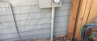
On an overhead line pole
If there is an additional input device in the section where the supply line is connected to the main ASU located at the serviced facility (on a pole, for example), then the GZSh can be mounted directly on it.
The requirements of current regulations (the same PUE, for example) require connecting a grounding bus mounted on a pole to the main distribution strip located in the internal input device.
Also, one should not forget about organizing the re-grounding of the PEN conductor on the pole by separating a separate PE grounding bus from it. The latter means that the specified structural element must be electrically connected to another grounding circuit, installed directly under the support.
In the ASU cabinet
The cabinet with the main busbar mounted in it can be placed directly on the facade of the house in a place previously provided for this. At industrial facilities and in buildings of various organizations, the installation of ASU, as a rule, involves the use of a special panel room for these purposes.
If the switchgear is located outdoors, the cabinet body must have an IP index corresponding to its operating conditions.
Installation of structural elements that implement a functional (working) grounding bus involves a whole set of special operations, during which the following points must be taken into account:
The cross-section of the PE grounding plate must be at least 10 mm2 (if it is made of copper). For a steel conductor this value cannot be less than 75 mm2.
Installation outside the cabinet
Outside the cabinet, the main grounding bar must be installed in places protected from unauthorized access and interference.
It is fixed within the boundaries of a hard flat surface on insulators made of a sufficiently strong material. As an example of open placement of a gas shield, let’s consider the installation of a standard 19-inch plate of the “TLK” brand.
The TLK-ERH-CU grounding bars, widely used in electrical engineering, are a certified product from TLK that meets all previously agreed upon requirements. During their manufacture, 14 to 18 mounting bolts are placed on a copper rail with a standard size of 19 inches (19”) for connecting the supply conductors.
According to the requirements for structures of this class, such a 19-inch rail with 14 (18) connectors should be installed in special cabinets manufactured by the same trading company. And only after this the finished structure is connected to the grounding system using a copper wire of the appropriate section.
Additional Information. The cabinet used to accommodate the 19-inch rail is appropriately designated “No. 19.”
Another option for arranging a grounding bus is to use special DIN rails for these purposes, which fall into the category of standard electrical products combined in one cabinet.
According to current standards (GOST, in particular), a set of such DIN rails can be intended for other purposes (they can be used as strips for connecting phase and neutral conductors).
Purpose
In addition to the GZSh, the grounding system includes a set of copper connecting conductors, as well as a special structure made of metal profiles or fittings, called a grounding loop. The latter is dug into the ground not far from the building to a depth that ensures reliable contact of the metal with the ground.
The main purpose of the grounding bus is to create a special zone at the entrance to the structure that has zero potential with respect to the ground. In addition, the GZSh is intended for connecting parts of electrical equipment operated within the boundaries of a given facility and requiring grounding.
In most cases, the grounding bus collects conductors coming from the following structural elements:
In addition, the so-called “PEN conductor” is connected to the main grounding bus, which is part of the supply voltage cable supply and combines the “working zero” and the protective wire.
On the GZSh strip, the grounding bus is artificially divided into the so-called “zero working” (N) and “zero protective” (PE), each of which has its own fastening and is used for its intended purpose.
Results
In conclusion, we note that a fairly common method of connecting individual elements of the ground bus is welding.
It fully satisfies the GOST requirements for arranging reliable contacts. At the same time, the use of a welding device for assembly purposes ensures a strong connection with a guarantee of high conductivity.
We also note that the quality of bolted connections is ensured by reliable crimping of the cable lugs of the supply wires. In the same way (by bolting) the busbar in the tip is connected to the cabinet body.