Adjustment and repair of relay REL, N
1 External inspection and external cleaning of the relay
Check for the presence of stamps on the screws closing the housing, RTU labels, and manufacturer's markings. Check the cutouts of the ABCD EZhZIK code in the selectivity plate with the selectivity code for this type of relay (Table 1). Figure 4 shows the ABC selectivity plate of the REL-1600 IR relay.
Rice. 1 Fig. 2 Fig. 3
Rice. 4 Fig. 5 Fig. 6 Fig. 7
Table 1 - Selectivity codes
| Relay type | Selectivity code | Relay type | Selectivity code |
| ABVIK | REL1M-10 | ABJZI | |
| REL1M-600 | ABZIK | REL1M-5/200 | ABVGE |
| REL1-400 | ABEJZ | REL2-2400 | AUGWHERE |
| REL1M-160 | ABESI | REL2M-1000 | AVGJ |
| REL1-6.8 | ABESQ |
Report to the SNS about any deviations from the established standards.
Clean the outside of the relay from dust and dirt with a cloth. Check that the contact blades are perpendicular to the relay base. The knives should protrude by 8mm. Straighten bent knives by adjusting or using pliers. Clean the contact blades with an eraser, wipe with alcohol and dry with a napkin.
Rice. 8
We don’t check for rust on the guides in the TC is empty?
2 Opening the relay
Remove the mastic from the screws with a screwdriver, and unscrew the four screws securing the casing. Remove the casing and clean the inside with a cloth. Wet and remove the old MOUTH label. Check for mechanical damage (chips, cracks) of the casing, the relay base, and the tightness of the casing to the base. Bases and casings that are cracked or chipped must be replaced.
Rice. 9 Fig.10 Fig. 11 Fig. 12
No photo of fit
Rice. 13
3 Internal inspection of the relay
When inspecting the relay internally, check the wires of the coil terminals: the installation wires should not have any damage to the insulating coating, should be flexible, laid neatly without tension and should not interfere with the movement of the armature and loads. Inspect the reels: the reels should not have damage to the outer insulation, cracks or chipped spools. Check the reels for labels indicating the wire brand, diameter, and number of turns. Check the quality of the solder by trying to pull it out with tweezers. Soldering must be even, smooth, without traces of rosin. In solder areas there should be no unsoldered or broken conductors.
No photo with tweezers securing wires
Rice. 14 Fig. 15 Fig. 16
4 Contact system repair
Inspect the contacts: the contact springs should be smooth, without deformation or signs of bending. Check the integrity of the insulating plastic gaskets of the contact groups, the absence of chips and cracks in these gaskets. Replace faulty gaskets with new ones. Clean the silver hardening of the movable and stationary springs with fine-grained sandpaper and polish with an elastic band. If there is significant burn, clean the contacts with a flat “velvet” file, followed by grinding and polishing.
Rice. 17 Fig. 18 Fig. 19 Fig. 20
The graphite contacts of the relay must not have cracks or chips. Using tweezers, check the fastening of the graphite contacts in the metal holders by attempting to displace them. The distance between the contact surface of the carbon contacts and the lower edges of the metal holders must be at least 1.5 mm (for new contacts) and at least 1.0 mm for used contacts. Check by applying a 1 or 1.5 mm probe to the contact.
Grind the front contacts by pulling fine-grained sandpaper glued to the plate. After cleaning all contacts, wipe them with alcohol and then with a clean cloth.
Check the reliability of the contact groups by grasping each contact group with tweezers and attempting to move it relative to the relay base.
Photo of the graphite probe
Rice. 21 Fig. 22 Fig. 23
Rice. 24 Fig. 25 Fig. 26
Replacement of defective contacts is carried out with the base removed without disassembling the entire contact system. Unscrew the screw of the required contact group, remove the defective contact and insert a new one, then secure the contact group with the screw. Move this to the block about replacing contacts and other components and develop
5 Repair and adjustment of the magnetic system
5.1. Anchor loosening
Remove the two screws securing the bracket to the yoke. Do not perform the following action during the lesson (the plate will already be bent):
Bend the corner of the armature plate slightly by adjusting it as shown in the figure. Remove one weight by turning it clockwise and lowering it. Remove the anchor with the shackle.
Rice. 27 Fig. 28 Fig. 29
Rice. 30 Fig. 31 Fig. 32
Clean cores, anchor, weights, yoke. Wrap a cloth around the screwdriver and wipe the yoke under the contacts. Wipe the yoke stop on which the anchor swings with a cloth soaked in alcohol.
Rice. 33
5.2. Preliminary adjustment of the contact pressure of the rear contacts
With the armature removed, install a 0.5 mm thick metal plate between all rear contacts and the rear contact stop (goose). Connect one lead of the light or sound indicator to the platinum. Consistently switching the second pin of the indicator to the rear contacts, measure the pressure of the rear contacts on the plate. To do this, apply the grammeter to the common contact until the light goes out or the indicator sounds turn off (until the rear contact and the plate open). The rate of pressing the rear contact onto the plate is 0.1-0.15 N (10-15 G). In case of deviation, bend the rear contact towards the general one (pressing less than 0.1 N) or away from the general one (pressing more than 0.15 N).
Remove the 0.5 mm plate.
5.3. Checking the adjustment of common contacts
Check the adjustment of the common contacts with the armature removed.
For full tees: pressing the common contact at which the common contact opens with the rear one should be 0-0.02 N (0-2 G). If I understood correctly of course.
For tees without rear contacts: there should be a gap of 1-2 mm between the common contact and the gooseneck (in the picture... adjustment of the right incomplete tee is required).
Adjust the general contact by bending the spring at the base.
+ photo of the fold of the common contact
5.4. Anchor installation
Check the Grover washers for cracks using a magnifying glass.
Reinstall the anchor and bracket. Press down on all common contacts from below with a screwdriver to bring the contacts to the same level. Insert the common contact tabs into the dielectric cutouts on the armature.
Place the plate on the bracket and screw the bracket to the yoke with Grover screws and washers. Do not tighten the screws. To ensure the standard armature play, insert a 0.2 mm feeler gauge between the bracket and the armature. Press the armature against the core and the bracket against the probe and armature. Tighten the screws securing the bracket. Check the gap between the armature and the bracket with feeler gauges (norm 0.1-0.25 mm): a 0.1 mm feeler gauge should go into the gap, but a 0.3 mm feeler gauge should not go through.
Maybe some additional photos of how to take the anchor with the bracket? during installation.
Insert the removed weight into the cutout on the anchor and rotate the anchor. Do not do what is written below in the lesson (leave the plate on the anchor slightly bent):
Straighten the plate on the anchor, securing the weight to the anchor.
After assembling the relay, check that the anchor and weights can move freely. The anchor and loads must move without snagging, both when the relay is in a horizontal position and when it deviates up to 5° from the horizontal position.
Well, are we going to check this or not???
Check and adjust the gaps between the weights and the limiter in the horizontal and vertical planes by bending the limiter. In Figure 2, the letter designations of sizes correspond to the following data:
G - 0.8-1.5 mm (with the armature released);
F - 0.2 - 0.5 mm (provide bending of the limiter);
E - 0.3 - 1.2 mm (provide bending of the limiter);
A - 0.5 - 1.5 mm (provide bending of the strips);
I - 0.1 - 0.25 mm (the gap between the anchor and the bracket is ensured by moving the bracket);
K - 0.1 - 0.25mm (provide bending of the bracket shelves)
* the gaps indicated in Fig. 2 should not be checked or adjusted, except for position I,
are specified structurally during the manufacture of the relay; use them as reference data.
* - TsShTs-37/142 dated 06/13/06. Deputy TsSH
Check and adjust play and clearances. They must comply with the established standards specified in Table 2. Check the gaps with feeler gauges, and check the gaps using a movement indicator with a division value of 0.01 mm.
Well, are we going to check this or not???
5.5. Checking armature backlash and clearances
Check the armature play along the prism (norm 0.1 - 0.5 mm) by installing probes in the gap between the armature and the bracket: a 0.1 mm probe should go into the gap, a 0.55 mm probe should not.
Gap between armature and core
To check the gap between the armature and the core, press the armature against the core with your hand. A 0.15 mm feeler gauge should pass under and above the diamagnetic plates in the gap.
5.6. Checking the armature stroke
Clamp a 0.35 mm feeler gauge under the diamagnetic armature stop. Make sure all front contacts are closed. If the contact is not closed, adjust it by bending the thrust spring of the front contact towards the common one.
Parameter name
Limit values, mm
1 The gap between the pole and the armature in the attracted position after covering them with a protective layer, not less than 0.15 2 The backlash of the armature along the yoke prism is 0.1-0.5 3 The armature stroke, measured under the stop, ensuring contact slippage, is not less than 0.356 Adjusting the contact system
The relay contacts must be adjusted so that the mechanical characteristics of the contact system after adjustment comply with the standards given in Table 3. When adjusting the contact system, it is allowed to slightly bend the contact and thrust springs.
Table 3 - Mechanical characteristics of the contact system
| No. | Parameter name | Limit values |
| 1 | Contact opening with the anchor pulled and released, not less than, mm | 1,3 |
| 2 | Contact pressure on contacts is not less than, N(Gs), frontline rear | 0,3 (30) |
| 0,15 (15) | ||
| 3 | Permissible deviation along the contact path (non-simultaneity), no more, mm | 0,2 |
6.1. When the armature is pulled all the way to the stop, the plates of all rear contacts must rest on the stop, and there must be a visible gap between all the plates of the front contacts and their thrust plates. When the armature is released, the plates of all front contacts should rest on the thrust plates, and there should be a visible gap between the rear contact plates and the stop.
Make the adjustment by bending the thrust springs of the front contacts and ??? But how can you ensure clearance at the rear if there is none?
6.2. Checking the simultaneous closure of contacts
Slowly pressing the armature against the core with your hand, check the simultaneous contact of the common and front contacts. If the contacts do not close simultaneously, check the admissibility of non-simultaneity (no more than 0.2 mm), to do this, determine at which probe placed under the armature the first contact closes and at which the last one. The difference should be no more than... ? mm.
In case of deviation from the norm, bend the thrust spring of the contact that closes first (towards the front contact) or last (towards the common contact).
I wonder if the simultaneous closing of the rear ones should be checked or not?
6.3. Place a 1.1 mm thick probe between the armature stop and the relay cores and press the armature. Check that there is a minimum uniform clearance between all common and rear contacts. If necessary, make adjustments by bending the arms of the anchor in the area of the weakened section.
???? I don’t like the bends of the anchor???
6.4. Possible deviation of one of the moving contacts from the general line of the moving contacts, eliminate the application of vertical force by adjusting the spring of the moving contact near the silver hardening.
6.5. Measuring and adjusting contact pressure
Adjust the contact pressure of the rear contacts to general. Place the relay in the horizontal operating position. Place a gram meter near the location where the rear contact hook is attached. It is more convenient to use a gramometer with a long beak. Press the spring until a gap forms between the common and rear contacts (or until the indicator lights up). The pressure must be at least 0.15 N (15 G). If the pressure is less than normal, bend the rear contact closer to the general adjustment.
+ photo rear adjustment
You can’t see the beak in the photo, where should I put it?
Measure the contact pressure of the front contacts. Press the anchor against the cores. Place the gramometer lever on the graphite contact cup and lift the spring up. Control the contact pressure at the moment of separation of the front contact from the general one. The rate of pressure on the front contacts is 0.3-0.32 N (30-32 G). Adjust the pressure by bending the front contact spring at the base.
6.6.
Place a 0.4 mm thick probe between the armature stop and the cores and press the armature against the cores. All normally open contacts must be closed. If the contacts do not close, bend the thrust plate of the front contact of this tee towards the common contact (in the figure ... line 1).
Place a 0.5 mm thick probe between the armature stop and the cores and press the armature against the cores. All front contacts must be open. Make the adjustment by bending the thrust spring of the desired tee towards the front contact (in the figure...line 2).
6.7. Checking and adjusting the intercontact distance
Press the armature against the core, check the gap between all rear and common contacts by trying to insert a 1.3 mm round feeler gauge into the gap. Release the armature, place the relay in the operating position, and similarly check the gap between all common and front contacts. If necessary, make adjustments by bending the thrust springs of the front contacts or... what if the rear contacts are less than normal?
7 Checking the parameters of the relay windings
Set the multimeter to measure resistance in the 200 or 2000 Ohm range. Measure the resistance of the winding pairs by connecting the device terminals to pins 1-4 and 2-3. at least I wrote the conclusions correctly
+ photo of multimeter settings COPY FROM OTHER TECHNIQUES
The resistance of the windings at a temperature of +20±5°C must correspond to the data specified in table 4.
Table 4 - Winding resistance
| Relay type | Number of turns of one winding | Resistance of one winding, Ohm |
| brand |
Features of the retractor relay device
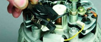
In order to independently repair any part in a car, you need to understand how it works. This will give you an idea of what elements are inside, how they work, and, accordingly, how to get to them for repair.
The solenoid relay is a capsule containing an electric magnet, a return spring and a rod. A magnet consists of two windings: a retracting core, and a winding that holds it in a certain position. It is their work that moves and fixes the core inside the mechanism.
As soon as the key is turned when starting the engine, the battery supplies electricity to the windings, which perform the retraction function. As a result, an electromagnetic field appears around the core, which sets it in motion. At the same time, the return spring is compressed, which will then return it to its original position. Together with these movements, the opposite end of the part is attached to the flywheel. Due to this, the gear connected to the bendix is connected to the flywheel and transmits movement to it.
As a result of all these manipulations, the engine starts. After which the mechanism turns off the electric current inside itself and returns all its parts to their original position. Only the core remains in its original position thanks to one of the windings.
Reference. There are relays with only one winding that has a pull-in function. But such parts are not common due to the fact that they consume a lot of electricity, and as a result, drain the battery faster.
Signs and causes of relay failure
If the relay is broken, the following signs will tell you about it:
- when you try to start the engine with the key, it does not start, or starts only after two or three attempts;
- There is a buzzing sound after the engine starts. This means that the starter rotates at higher speeds, although it should no longer be.
If at least one of these signs is observed, then this is a reason to be wary. The relay may soon break. There are several reasons why this happens:
- one of the windings, or both, were burned or broken at once;
- deformation of the return spring inside the mechanism;
- a short circuit has occurred inside the part on one of the windings;
- The surface area of the contact plates has decreased, or they have completely burned out.
Understanding the reasons why the relay fails, repairs will take less time, because It’s immediately clear where to look for the problem.
Why doesn't it work and what to do about it?
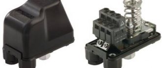
If the diagnostics showed that the pumping station itself is working, then you should pay attention directly to the pressure switch. The algorithm of actions will depend on how the malfunction of this unit manifests itself.
Works often
When the pressure in the hydraulic tank is stable, the main reason for spontaneous frequent starts of the pump is a failure of the automation settings. For adjustments, a pressure gauge must be connected to the system.
The most popular relay in local water supply is RDM-5, with preset response threshold settings:
- lower pressure - 1.4 atm.,
- upper - 2.8 atm.
Step by step, this standard relay is adjusted as follows:
- Remove the unit cover.
- By right-hand rotation of the larger spring nut, raise the shut-off pressure to the desired value, for example 3.8 atm. At the same time, the lower launch limit will also rise.
- By turning the regulator of the smaller spiral to the left, set the desired pressure delta.
Spirals, especially smaller ones, are very susceptible to adjustments, so they should be adjusted very carefully, with gradual tightening of the nuts at 45° turns.
Doesn't turn off the pump
The most common reasons why the relay does not operate to turn off the pump include:
- Sticking and, in severe cases with powerful starting currents, melting of the breaker contacts. If the contacts are not damaged, the defect can be eliminated by cleaning them with fine-grained sandpaper, a fine needle file or a nail file.
- The difference between the relay response thresholds is too high. You should set the settings recommended by the manufacturer or optimal for a particular pump.
It is advisable to maintain the pressure delta in the range from 1.2 to 1.6 atm.
Clicks and switches off frequently
In practice, you can encounter another malfunction of the automation unit responsible for water pressure - periodic clicking.
If the reason is not related, as described above, to a breakdown in the water supply system itself (usually airing) or lack of pressure in the hydraulic tank (ruptured membrane), then the problem is in the automation.
Having summarized numerous opinions on this problem on engineering forums, we can conclude that there is only one possible solution to it - try to eliminate the frequent operation of the automation (clicking) by increasing the difference in the relay response thresholds.
If this does not solve the problem, then the only option is to replace the unit.
It just doesn't work
The relay may not close to turn on for the following reasons:
- Insufficient voltage in the network - automation is demanding on this parameter.
- Oxidation of the contact group - it is necessary to disassemble the device and clean the contacts.
- The automatic shutdown pressure limit is set too high.
- Lime and other deposits in the five-pin fitting with a pressure gauge connecting the relay to the pump (five-pin), or the hole in the membrane compartment is clogged - you need to remove the relay and clean the part.
- Sand gets into the membrane part of the block, which interferes with the action of the diaphragm on the piston. The latter is often observed if the pump has pumped sand. It is necessary to disassemble the relay, carefully clean and rinse everything.
Adjusting the pressure in the pumping station
Setting up the pressure switch begins with checking the compressed air pressure in the hydraulic accumulator. In this case, the pumping station should be disconnected from the network and the accumulator tank should be empty. To do this, unscrew the side cap on the tank (see figure - red arrow) and use a regular car pump with a pressure gauge to check the pressure. It should be about 1.5 atm. If the measured value is less, the pressure must be raised by the pump to the required level. It should be noted that the air in the tank must always be under pressure, and when operating the pumping station it must be checked from time to time and pumped up if necessary, which will increase the service life of the accumulator membrane.
If, after adjusting the pressure in the accumulator, the pumping station does not operate normally, you need to start setting up the pressure switch itself. It should be remembered that the pump switch-off pressure (upper setting) should not exceed the pressure that the pump is capable of developing!
What type of relay can be repaired?
One of two types of relays can be installed in a car: collapsible and non-dismountable. If the car has the second type of relay, then you won’t always be able to fix it yourself.
A non-separable relay can only be repaired if the contact plates are burnt. If one of the windings has deteriorated or a short circuit has occurred in them, then it will no longer be possible to repair it - only replacing the part.
Important! In case of self-repair, when removing the relay, it is recommended to mark the terminals so as not to confuse them when installing the mechanism in place. It is also a good idea to clean and degrease the contacts on the relay and starter.
Relay Crackling Rating:
#1 berlon
- Active participant
- Posts: 194
- Registration: 22 July 09
- From: Chisinau
- Interests: 9477399two - ICQ
I haven’t done any nonsense for ten years and here I am. took up the problem.
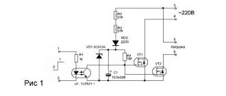
I connected the relay in series with a 220V lamp. It needs to work and keep contact (to further close the circuit to 12 volts) But the relay crackles and the lamp blinks) Apparently I’m stupid. maybe a diode, maybe what else is needed?
Attached images
#2 JekaJeka
- Active participant
- Messages: 300
- Registration: 03 July 09
- From: Kirovograd
I ask you to express all hostility towards me exclusively in a suicidal form .
#3 berlon
- Topic Creator
- Active participant
- Posts: 194
- Registration: 22 July 09
- From: Chisinau
- Interests: 9477399two - ICQ
#4 JekaJeka
- Active participant
- Messages: 300
- Registration: 03 July 09
- From: Kirovograd
berlon said:
So plug the relay parallel to the light bulb, if it is on 220V alternating, then it should not buzz (crackle)!
I ask you to express all hostility towards me exclusively in a suicidal form .
#5 berlon
- Topic Creator
- Active participant
- Posts: 194
- Registration: 22 July 09
- From: Chisinau
- Interests: 9477399two - ICQ
#6 JekaJeka
- Active participant
- Messages: 300
- Registration: 03 July 09
- From: Kirovograd
berlon said:
stupid question: does this not work as a short circuit? the coil will overheat. it seems to be rated for 5 amperes, but there is no load on the line
So. To relieve all fears and worries, take a photo of the reel, where the markings and symbols are, or, as a last resort, rewrite it. If everything is connected correctly, no short circuit. will not be! The relay is switched on by a working winding (usually two separate contacts) directly to the power source, consumes very little current and is designed for round-the-clock operation. And a current of 5 amperes is the current that the contact group can withstand. Give me some pictures. />
I ask you to express all hostility towards me exclusively in a suicidal form .
#7 berlon
- Topic Creator
- Active participant
- Posts: 194
- Registration: 22 July 09
- From: Chisinau
- Interests: 9477399two - ICQ
#8 Gorn
- Active participant
- Posts: 591
- Registration: December 10, 10
- From: Svetlovodsk
#9 JekaJeka
- Active participant
- Messages: 300
- Registration: 03 July 09
- From: Kirovograd
I ask you to express all hostility towards me exclusively in a suicidal form .
List of common breakdowns
Typical causes of automation problems include:
burnt contacts;- salt deposits on the coils;
- clogged and rusty hydraulic inlet;
- the entry of sand and other foreign particles into the membrane compartment and the formation of deposits;
- incorrect mechanical settings of the automation.
Another reason for a failure to pump water, which is not directly related to a malfunction of the relay itself, can be voltage surges in the electrical network.
How to check the starter solenoid relay?
When checking the relay, first of all you need to look to see if the wiring connecting it to the starter is broken. This is done simply: we look visually and look for places of ruptures. Then, we try to start the engine, if there is a sound of operation - everything is in order with the wires.
There are times when when you turn the key, a click is heard, but the starter does not rotate, which means the contact plates are burnt. You can check this by applying voltage to the car engine, bypassing the relay. In this case, the relay terminals are disconnected from the lock. Then use a screwdriver to close the terminals located on the battery and on the starter. If rotation begins, then there is a problem with the retractor.
There is another way to check the starter. This is done as follows:
- The relay contacts are connected by short wires to the plus and minus of the battery.
- The negative end of the wire is not connected to the battery. It is placed on contact. If at this moment there is a click, then the part is working properly, if not, then the part is faulty.
