There is no universal soldering iron and soldering temperature that is suitable for absolutely all cases. Much depends on the solder, on what materials the master works with, as well as on the goals he pursues.
And in general, choosing the optimal temperature is not such a simple matter. Typically, the soldering iron tip is heated until it begins to melt the solder. But in some cases more fine tuning is required.
Accessories necessary for soldering and desoldering
A soldering iron is a tool used for soldering. A soldering iron consists of a handle and a tip that heats the solder. The tip is very hot, be careful not to burn yourself or accidentally set fire to surrounding objects!
Soldering iron
Solder is most often made from tin and lead, which melts at 185 C. But recently, due to restrictive lead-free environmental standards, a tin-based alloy with an admixture of silver, copper, bismuth or antimony has been used, which has led to significant increasing the melting temperature to 220 C, and therefore it became more difficult to solder it with a “regular” soldering iron. Fortunately, tin and lead solders are still available.
Solder
Rosin is an easy-to-melt resin that makes soldering easier because the tin flows better over surfaces. Rosin dissolves well in alcohol, for example in salicylic alcohol - you can use it and dissolve the resin, and then carefully apply it with a brush to the board that you will solder, and thereby make the work much easier.
Rosin
Tin suction device (also known as a tin pump or extractor) - used to suck out excess molten solder. This is a simple syringe tool consisting of a piston, a spring and a receptacle for suctioned solder. It has a replaceable suction tip on one side, a handle on the other, and a release button on the side.
desoldering pump
Soldering braid is braided copper wires that, when applied to hot tin on soldered elements, absorb the excess.
Solder braid
Pliers - they are used to cut off the legs of the soldered elements (you can use ordinary cosmetic pliers, but they get damaged quite quickly).
Nippers: a) ordinary; b) cosmetic
Other soldering supplies:
Flux - simplifies soldering by removing impurities from the soldered surface, facilitates melting, and increases the fluidity of tin. Flux, unlike rosin, does not leave brown marks, but flux residues must be removed (for example, with acetone) as they can cause corrosion.
Soldering flux
Tweezers - makes it easier to hold a small soldered element, since if you hold it with your hand, you can get burned.
Tweezers
Cleaner - for cleaning the hot tip of the soldering iron from tin residues and other contaminants.
Tip cleaner
The following are photos of different types of universal circuit boards - single-sided and double-sided:
Universal boards: a) single-sided - solder points on one side only; b) double-sided - solder points on both sides
Tip temperature relative to the solder used
The operating temperature of the soldering iron is selected separately for each process. When soldering contacts of the same type using the same solder, the same tool parameters can be used. In other cases, you even have to change the soldering iron to adapt to the desired characteristics. To work with certain solders, the temperature of the soldering iron should always be slightly higher than the melting point of the solder. The difference should be small, only 5-10 degrees. With modern technology, such indicators are easy to achieve if you have a power regulator and an accurate heating sensor.
Soldering safety
- The tip of a hot soldering iron has a very high temperature, making it easy to set fire to something, melt plastic objects, or burn yourself.
- It is natural to hold a heated soldering iron only by the handle intended for this purpose.
- Do not disassemble the soldering iron - this may lead to electric shock, since during assembly, reliable insulation of the heating wires (220 V) from the metal of the case is not guaranteed.
- Solder fumes are toxic regardless of the filler metal used. Be careful not to inhale them. Make sure the room you are soldering in is well ventilated.
In addition, when soldering, it is recommended to protect your eyes, for example by wearing safety glasses - if you accidentally get on the liquid, hot solder can splash out to the sides. Remember what happens when you pour lead into water?
Wire soldering technique
Procedure for how to solder wires correctly:
- Remove the insulation to the desired length, usually 3-5 cm.
- If necessary, clean and degrease the wires (depending on the type of wire).
- Twist the wires tightly together.
- Cover the soldering area with flux.
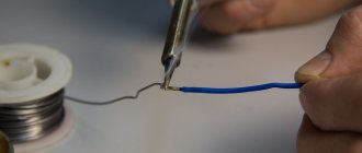
- Place solder on the tip and solder the twist. It is important to heat the wires evenly so that the solder covers all surfaces and fills the cavities.
- Insulate the resulting connection using heat shrink tubing (must be put on before soldering) or regular electrical tape.
There are different ways to connect and solder wires. They don't always have to be twisted. If the wires are soft, for example made of copper, it is better to twist them to ensure reliable contact.
If the wires are hard and brittle, they can be placed next to each other and then soldered without twisting. This will eliminate the risk of fracture during twisting.
When soldering without twisting, it is highly recommended to pre-tin both wires. Instructions on how to tin wires with a soldering iron:
- Strip each wire of insulation.
- If necessary, remove the varnish from the wires. This is best done with a sharp knife or sandpaper.
- Treat the core with flux.
- Apply molten solder evenly to the surface using a soldering iron.
A properly tinned wire should be completely covered with a layer of solder. Next, these wires are twisted or tightly applied to each other and soldered. You don't need to use a lot of solder, since each of the wires is already coated with it.
Soldering electrical components on a universal board
So, enough theory, let's move on to practice. Select the appropriate universal circuit board. It is made of fiberglass and has many holes drilled into it. This printed circuit board is double-sided, which means that we can solder elements to it on both sides. In single-sided universal boards, we solder components only on one side; on the side of the soldering points, there are silver rings around the holes.
The soldering iron should be connected to a power source (USB, station or 220 V network) and placed in a safe place, the tip should be in the air so as not to melt anything and not get burned by accidentally touching it (you will get burned anyway, more than once).
Soldering iron on a plate
The tip warms up for some time. For now, insert the legs of the soldered element through the corresponding holes in the printed circuit board. Also prepare rosin.
The resistor legs are threaded through the holes in the universal board
Now bring the soldering iron tip closer to the board and the soldered leg.
Using a soldering iron to heat resistor legs being soldered
Then touch the tip to the part. Do this quickly, as if you hold the tip too long, too much stuff will melt. The entire process of soldering one solder should take 2 to 3 seconds.
Solder the resistor leg by simultaneously applying a hot soldering iron tip and tin
We will remove the tin so that excess does not remain at the soldering site
Solder the second leg of the resistor to the board
Correct (left) and incorrect (right) soldering:
The resistor legs are soldered to the board: left - right; correct - incorrect (too much solder)
a) correct; b) incorrect (too much tin, solder looks like a ball); c) wrong (too little)
Use pliers to cut off the legs of soldered components that are too long.
Cutting with pliers near the end of a resistor leg that is too long
Soldered resistor with cut lead (left side); long lead (right)
Preparing the soldering iron and parts
If the soldering iron is new, you need to turn it on for a few minutes and let it run “idle”. This is necessary for the factory grease to burn out. With such preparation, the soldering iron may smoke, so do not be alarmed.
Usually soldering irons are sold with a tinned tip (coated with a layer of tin). If the tip is uncovered, it needs to be lightly sanded with sandpaper, heated, then dipped in flux and coated with solder.
Sometimes even a tinned tip needs to be lightly cleaned before soldering. During operation, the tip becomes covered with an oxide film, which impairs the adhesion of solder. To do this, lightly clean it with sandpaper or a cloth, depending on the degree of contamination.
To prepare the parts you need:
- Remove the insulation (if wires are soldered).
- Degrease.
- Coat the part with flux.
- Tin with a soldering iron.
Then you can proceed directly to soldering. It is usually necessary to tin both parts. To remove oxides, you can use a soldering iron tip, sandpaper or a sharp knife.
Cleaning the soldering iron
The sponge for cleaning the soldering iron should be moistened with water. Carefully wipe the hot soldering iron tip with several quick movements. Holding the tip in one place for too long can damage the sponge.
Cleaning (wiping) the tip of a dirty soldering iron with a damp sponge
The soldering iron tip does not need to be cleaned after soldering a single element. This should be done if the tip is noticeably dirty.
Melting various materials
The craftsman may well need to solder copper - for example, we are talking about heating pipes or other products made from this non-ferrous metal.
You can work with a soldering iron with copper and its various alloys using different solders, both soft and hard. At the same time, the temperature of soldering copper elements with soft solders is 250-300 ℃, and with hard solders – 700-900 ℃.
What should be the temperature of the soldering iron tip if you need to solder, say, polypropylene products? In this case, the optimal temperature will be +260 ℃, and the conditional permissible range is from +255 to +280 ℃.
But it is worth noting that if you overheat the soldering iron above 271 ℃ and reduce the heating time of the tool, the surface of the soldering zone will warm up much more than the inside. This means that the resulting sealing film will be very thin.
Solder joint defects
Solder joint defects are considered to be:
- Solder joints with cracks.
- Broken solder joints.
- "Cold" soldering. The term “cold joints” refers to solder joints formed with signs of incomplete reflow, such as a grainy surface appearance, an irregular joint shape, or incomplete fusion of solder particles.
- The solder fillet violates the minimum electrical clearance between pads or leads of a component, or touches the component body. Solder fillet - the surface formed by solder during the soldering process
- Lack of wetting or poor wettability of a contact or pad - lack (full or partial) of the ability of a pad or plated contact of a component to be wetted by molten solder, reducing the area of the pad or lead covered by solder.
- Solder jumpers between connections, unless electrical contact between these connections is required by the product design
Criteria for assessing the quality of solder connections of lead components mounted in the mounting holes of the board
Contact angle between solder fillet and PCB pad
A sign of a good solder joint is the presence of low or zero contact angles (Ө) between the solder fillet and the pad (angle Ө less than 90˚). The solder fillet is concave; the solder on the attached element forms a frozen seam.
A sign of a poor-quality solder joint is the formation of a solder fillet with a contact angle ( Ө) equal to or greater than 90˚.
Defect – for classes 1, 2, 3:
● Unsoldered – The solder formed a bead on the surface similar to what water forms on a waxed surface. The solder fillet is convex, the contact angle ( Ө) is greater than 90˚,
the frozen seam is not visible. (Reject - marriage).
Protrusion of leads above the board pads
The protrusion of the leads should not lead to violation of the minimum electrical clearance, damage to solder joints due to deformation of the leads, or penetration of the leads through the protective antistatic packaging (film) during subsequent operations or during operation of the product.
The leads protrude above the contact pad in the range from Lmin to Lmax of Table 1, unless there are special requirements in the design documentation.
Table 1. Lead protrusion
| Class 1 | Class 2 | Class 3 | |
| Lmin1 | The end of the lead is visible in the solder 2 | ||
| Lmax | No risk of short circuits | 2.3 mm | 1.5 mm |
Note:
1 For single-sided boards, the lead or wire protrusion (L) is at least 0.5 mm for classes 1 and 2. For class 3, there must be sufficient lead protrusion to differentiate.
2 For boards thicker than 2.3 mm with metallized mounting holes, the protrusion of component pins in DIP packages, sockets, and connectors with fixed-length pins may not be obvious.
Defect – for class 3:
The protrusion of the leads does not meet the requirements of Table 1.
Filling the plated mounting hole of the board with solder and wetting the lead and the walls of the hole with solder
When installing lead elements into through metallized holes, the solder must well wet all contact surfaces, wetting the walls and filling the hole with solder must comply with the drawing and the requirements of Table 2:.
1 - Height of filling the hole with solder. 2 - Component installation side. 3 - Soldering side.
Table 2. Soldering of lead components into metallized holes, minimum acceptable quality criteria for solder joints.
| Parameter1 | Class 1 | Class 2 | Class 3 | |
| A | Circular solder wetting of the component lead and the board pad on the component mounting side | Not regulated | 180˚ | 270˚ |
| B | Solder hole filling height 2 | Not regulated | 75% | 75% |
| C | Circular solder wetting of component lead and board pad on solder side | 270˚ | 270˚ | 330˚ |
| D | Area of contact pad wetted by solder on the installation side of the component | 0 | 0 | 0 |
| E | Area of contact pad wetted by solder on the soldering side | 75% | 75% | 75% |
Note:
(1) Refers to the solder applied during the soldering process.
(2) The unfilled 25% of the hole height includes the unfilled solder cavities on the solder side and on the component mounting side, that is, on both sides of the board in total.
Please note: Some product applications may require the mounting hole to be 100% filled with solder. This condition must be additionally specified in the technological process.
Defect – for classes 1, 2, 3:
solder connection does not comply with table 2.
Vertical filling of the mounting hole with solder:
Standard – for classes 1, 2, 3:
100% wetting of the lead, contact pads and walls of the metallized mounting hole with solder, completely filling the mounting hole around the lead with solder:
- component output;
- solder;
- contact area;
- mounting hole wall;
- PCB solder mask;
- base material of the printed circuit board (pressed layers of fiberglass impregnated with epoxy resin, laminated with copper foil);
- metallized conductive layers of a multilayer printed circuit board.
Acceptable – for classes 1, 2, 3:
at least 75% of the height of the mounting hole cavity is filled with solder; it is allowed that the height of the hole not be filled with solder by 25% (in total on both sides of the board):
Defect - for classes 2, 3:
The vertical filling of the hole with solder is less than 75%.
Peripheral (circular) solder wetting of the lead and the wall of the mounting hole on the solder side
Acceptable - for class 3:
At least 270˚ (3/4) of the hole diameter, the lead and the wall of the mounting hole are covered with solder.
Defect – for class 3:
Less than 270˚ (less than ¾) of the hole diameter, the lead and the wall of the mounting hole are covered with solder.
Solder wetting the annular pad of a plated mounting hole on the mounting side of a component
Acceptable – for classes 1, 2, 3:
The pad on the mounting side of the component may not be covered with solder.
Solder wetting the annular pad of a plated mounting hole on the solder side of a component lead
Acceptable - for classes 1, 2:
at least 270˚ (¾) along the diameter of the mounting hole, the solder fillet covers the ring pad, the walls of the hole and the lead.
Acceptable - for class 3:
at least 330˚ across the diameter of the mounting hole, the solder fillet covers the ring pad, the walls of the hole and the lead.
Acceptable – for classes 1, 2, 3:
Solder wets at least 75% of the ring pad area of the mounting hole.
Distinction of the end of the lead in the solder
Acceptable - for classes 2, 3:
the fillet is convex; the end of the lead is indistinguishable due to excess solder, but the presence of a lead in the hole on the installation side of the component is visually determined.
Defect – for classes 1, 2, 3:
the end of the lead is indistinguishable due to excess solder; from the component installation side, the lead is deformed and it is not obvious that the end of the lead is completely inserted into the mounting hole.
Solder on the molded part (on the bend, “shoulder”) of the component lead
Acceptable - for classes 1, 2, 3:
Solder has flowed onto the lead bend but is not touching the component body.
Defect – for classes 1, 2, 3:
Solder has flowed onto the “shoulder” of the lead and touches the component body.
LIST OF MAIN AND AUXILIARY MATERIALS,
approved for use during maintenance or soldering operations
Specific tinning or soldering materials are specified for each product on the process sheets.
- Solder wire PRv KR1 or PRv KR2 POS 61 GOST 21930-76, Ø 1 mm, Ø2 mm .
- Single-channel tubular solder POS 61T1A GOST 21930-76 , Ø 1 mm, Ø 2 mm.
- Multichannel tubular solder with flux that does not require cleaning , SN62 X39 f. Multicore Solders (based on alloy SN 62, silver-containing), Ø 0.56.
- Multichannel tubular solder with flux that does not require cleaning, SN60 X39 f. Multicore Solders (based on SN 60 alloy), Ø 0.7 mm, Ø 1.2 mm.
- Multichannel tubular solder with flux that does not require cleaning, JM-20 f. Koki (based on alloy SN 60), Ø 0.8 mm, Ø 1.0 mm, Ø 1.2 mm.
- Multi-channel tubular solder with no-clean flux, 60EN Crystal 502 f. Multicore Solders (based on SN 60 alloy), Ø 1.2 mm.
- Multichannel tubular solder with flux that does not require cleaning, CW-801 f. Indium (based on alloy SN 63), Ø 0.8 mm, Ø 1 mm.
- Alcohol-rosin flux FKSp OST 4G 0.033.200 .
- Solid flux “pine rosin grade “A”” GOST 19113-84.
- One-component flux, no cleaning required, X33-12i (MF-210) f. Multicore Solders or WF-9942 f. Indium.
- Ethyl alcohol GOST 18300-87.
- Nefras S2 80/120 TU 38 401-67-108-92
- Flushing liquid VIGON EFM f. Zestron .
- Silver braid for removing solder (outer conductor of radio frequency cable RK-75-1-22 TU 16.505.198-91 ) or copper braid DESOLDERING WICK or similar.
- Round panel brush KFK No. 8, No. 12 GOST 10597-87 .
- Flat panel brush KFP No. 8, No. 12 GOST 10597-87.
- Artistic brush KHZhK No. 1, No. 3 “squirrel” OST 17880-80.
- Cotton scraps art. 361 GOST 4644-75.
- Knitted gloves with polymer coating, type Multex code Per 306 according to catalog f. Tract.
- Antistatic gloves ESD CLOVES 8745 PVCB 6 .
- TTC-LF paste or similar for cleaning and tinning tips.
Advantages of Brazing Solders
Advantageous applications of brazing alloys:
- PSr72 and PSr50 – for soldering metal-ceramic contacts and various conductive parts that must withstand impacts and bending.
- PSr45 - in order to solder copper elements and its alloys, as well as stainless steel parts, rotor windings and windings of loaded electrical devices. This solder gives greater density, and at the same time greater strength of the resulting joints.
- PSr25 – for soldering copper elements or parts from its alloys, stainless steel parts. It is a substitute for PSr45 when creating simple adhesions.
- PSr71 - for soldering the same parts as PSr72, but is used when high fluidity is required.
- PSr25f; PSr15 and PMF7 - for soldering copper or copper alloy parts, parts of devices that conduct current, which should not withstand bending and impacts.
- L63 and LOK59-0.1–0.3 - for soldering copper parts or cast iron parts. This soldering is very strong and suitable for difficult bending and impact conditions.
- PZHL500 – soldering of parts, with operating temperatures up to six hundred degrees Celsius.
Nichromes
For the manufacture of heaters and powerful resistances, alloys with the following requirements are required:
- Relatively high resistivity - otherwise the heater will have to be made long and thin, which will negatively affect durability.
- Resistance to oxidation in air. If air gets into the bulb of an incandescent lamp, the spiral will burn out very quickly. At high temperatures, the rates of chemical reactions increase, and oxygen in the air begins to oxidize even metals that are stable at room temperature.
- Have acceptable mechanical characteristics. Low ductility and increased fragility will negatively affect the reliability of the product.
Heaters are usually made from the following alloys:
Nichrome
(55-78% nickel, 15-23% chromium) operating temperature up to 1100 °C, although nichrome is a whole class of alloys with a slight difference in composition.
Fechral
, the name is derived from the composition FeCrAl (12-27% Cr, 3.5-5.5% Al, 1% Si, 0.7% Mn, the rest Fe) operating temperature up to 1350 ° C (Sometimes called kanthal - kanthal, this is not a brand of alloy, but a trademark that has become a household name, such as “thermos”).
The addition of chromium ensures the formation of a protective film on the surface of the alloy, due to which nichrome heaters can operate for a long time in air with a high surface temperature.
Fechral becomes brittle after heating. After heating, nichrome can still be bent somehow. At the same time, fechral is cheaper than nichrome, not so noticeable in retail, but noticeable in wholesale quantities.
A nichrome coil with a wick inside is an electronic cigarette vaporizer. A nichrome string heated by electric current is used to cut polystyrene foam. Also, insulation thermal strips are made from nichrome - today the most reliable way to remove insulation from a wire without damaging the conductor.
Surprisingly, it is quite difficult to buy nichrome in the form of wire in small quantities; local sellers do not even want to hear about quantities of less than a kilogram. So, if you need to make a heating element, it’s easier to rewind nichrome from some faulty fan heater.
The ends of the heating elements are usually welded to the current conductors or clamped mechanically - with a screw or crimping.
