Many people who begin to get involved in the study of electricity and the basics of designing this section of engineering networks often do not have the opportunity to gain proper practical experience. In theory they see one thing, but when reading electronic circuits they see something completely different. For beginners, electronic circuits seem difficult not only to use, but also when trying to decipher them. It is best to start studying the practical part with diagrams containing the simplest electronic base and primitive symbolic images. The material below will contain simple electronic circuits with a description and their basic symbols for beginners.
Hidden wiring detector
A hidden wiring indicator is a special device for detecting an electrical network laid in grooves under the plaster of a wall. Even simple repairs to home electrical wiring and sockets cannot be done without it. The device is necessary when the old wiring in the walls was laid without executive circuits, and it is impossible to determine the location of its installation in the absence of a special device. When performing repair work, the integrity of the insulation of hidden wiring may be damaged by a drill or nail. Such actions can cause electric shock and also disable the entire home network.
Detector chip for hidden wiring
To detect hidden wiring, in most cases, a device made of a pointer or digital ohmmeter with a field-effect transistor will be sufficient. The body of the radio element is passed along a section of the wall and, if it “sees” the wiring, the values on the ohmmeter immediately change. The modified detector is shown in the diagram below. To make it you need:
- Battery;
- LED for indication;
- Transistor;
- Resistors: 1 Mohm, 100 kOhm, 330 Ohm and 220 Ohm;
- Switch to start working.
Detector parts
Automatic cooler speed controller
This device will be useful both for ordinary people and for PC repair and maintenance specialists. Often, manufacturers of computer components directly connect the power to the cooler that cools the processor or motherboard. This causes the device to continuously spin at maximum speed even though the PC is idle. By installing a homemade automatic regulator, you don’t have to worry about the processor temperature, because the sensor will turn on the cooling automatically when it’s really needed.
You might be interested in this Apartment wiring plan
Device diagram
The speed controller will not only increase the service life of the cooler, but also reduce the noise level in the room. It can be made using two transistors, a resistor and a thermistor.
Homemade product in the form of a cooler regulator
Wireless LED
This primitive device does not have any practical value, but is capable of surprising people who are far from electronics. It is an LED that begins to glow when not connected to a power source.
The circuit is based on a single transistor, which is an almost complete high-frequency current generator. The inductor is presented in the form of an ordinary wire, which is bent into the shape of a ring. The LED has a receiving loop that receives an electrical signal at some distance from the inductor and causes the light bulb to light.
Wireless LED circuit
For the diagram you will need:
- 6 AA batteries;
- Light-emitting diode;
- Transistor (BF494);
- 0.1 µF capacitor;
- 33 kOhm resistor;
- Inductor 330 µH;
- Wires.
"Magic" LED
General classification
The concept itself implies a set of symbols that are intended to identify any structural elements or parts. In accordance with the rules and requirements of GOST 2.701-84, several types are distinguished, differing both in the scope of application and in the type of symbols installed.
The breakdown by type is shown in the table below:
Table: varieties diagram
| № | Scheme type | Letter designation |
| 1 | Electrical | E |
| 2 | Hydraulic | G |
| 3 | Pneumatic | P |
| 4 | Gas (except pneumatic) | X |
| 5 | Kinematic | TO |
| 6 | Vacuum | IN |
| 7 | Optical | L |
| 8 | Energy | R |
| 9 | Divisions | E |
| 10 | Combined | WITH |
Thus, for the same device or object, if necessary, several diagrams can be developed at once, explaining the principle of connection, operation or implementation of functions. For electrical equipment, circuits are divided into several types:
- Fundamental or complete – indicated by the number 3;
- Structural – indicated by the number 1;
- Functional - indicated by the number 2;
- General – indicated by the number 6;
- Installation or connection diagrams - indicated by the number 4;
- Connections – indicated by the number 5;
- Locations and combined are designated by numbers 7 and 0, respectively.
When drawing up a specific diagram, as a rule, alphanumeric designations are used, for example, for an electrical functional marking it will look like E2, for a gas structural one X1, etc.
The principles of graphic designation of any elements on diagrams are determined by industry and state standards. They also establish requirements for the location of components, their sizes, and the application of codes, names or markings.
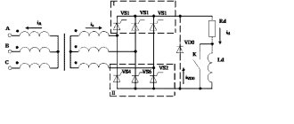
The simplest inverter without transistors
As you know from a theoretical physics course, an inverter converts direct electric current into alternating current. It is noteworthy that in most cases, when assembling such a device, it is quite possible to do without soldering. It is enough to connect all the contacts with a simple twist. The inverter, of course, will not last long, since the relay will sooner or later fail, but buying it again will not be a big problem. Sometimes you can even find an unnecessary switch from an old device or unsolder it yourself.
Important! The process of creating an inverter will help you understand the principle of operation of direct and alternating current, converting one type to another.
Inverter circuit
For the device you will need:
- Transformer from a radio receiver, with a winding of 220 and 12 Volts;
- 12 Volt relay;
- Wires for connecting parts;
- The load on the circuit is in the form of an ordinary light bulb.
Simple design inverter without soldering
Diagram of a simple metal detector
The simplest electronic circuits are based on a single chip, in this case the TDA0161, a specialized product for induction-based sensors. Based on these, metal detectors are assembled that react when approaching an induction sensor.
In some cases, these are located at factory entrances.
Parts for its assembly can be found in a radio parts store or on Aliexpress. In this circuit, the metal detector makes a sound only when it detects metal. The microcircuit operates in the range from 3.5 to 15 volts, when searching it consumes a current of about 1 mA, in signal mode 8-12 mA, at an operating frequency of 8-10 kHz.
You can power the device using a phone battery. Also, for a metal detector you will need a “working body” in the form of a coil with 140-150 turns of copper wire, 5-7 cm in diameter. In this case, the sensitivity directly depends on the diameter of the coil - the larger the coverage, the more sensitive.
The device should work immediately after assembly; the only thing it needs is to calibrate the response threshold with a variable resistor.
Circuit breaker
The circuitry of the device is extremely simple, but very reliable. The operating principle of the switch is based on the operation of a capacitor. When a button is pressed, the LED or lamp lights up. When the capacitor is completely discharged, the light source will go out. The operating principle is as follows: when you press the return button, the capacitor is charged and it turns into a “nutrient” element. When the switch opens the contact, the radio element will discharge and power the circuit in which the lamp is installed.
You may be interested in Description of the phase rotor
Electrical diagram of the switch on the button
Important! Since a capacitor cannot hold a charge forever, the light will sooner or later go out. It is difficult to say when this will happen, since everything depends on the characteristics of the radioelements used in the device.
Such a device would be useful, for example, in a cellar or technical underground. A person presses a button, takes the things he needs and, in order not to reach for the switch with a load in his hands, simply leaves the basement. When the capacitor is completely discharged, the light bulb will go out.
Assembled switch
sxemy-podnial.net
I present to your attention the fruit of my six-year search. The first attempts to implement the idea of a light switch began in 2013. I didn’t yet know the TTP223 and C005 microcircuits (and they probably didn’t exist yet), so I experimented with a push-button pseudo-sensor on my favorite K561LN2 microcircuit. I also didn’t have a BKVP yet - a unit of an autonomous optothyristor load switch with vampire power supply to external devices. There was only an idea and a little enthusiasm (why not much, because my job is a business trip, leaving home for several months, and there even no special ideas arise due to the intense working hours). The idea was to replace the light switch with a sensor (since there was no sensor either, it was a push-button pseudo-sensor) with automatic shutdown after a few hours. Well, this is for those who like to forget to turn off the lights, who accidentally went to sleep (of which I sometimes belong). In this case, the switch was supposed to “blink” the light (the sleeper will not see or react) when the timer for the shutdown timer came up, and after about two minutes, turn off the lighting if no one reacts to the warning. If during these two minutes, someone “shoots” the TV remote control (or claps their hands, it all depends on the type of sensor used), and the switch “hears” this signal, then in response it will “blink” the light and reset the shutdown timer. This is, perhaps, the whole job of the light switch. And one more thing - the whole circuit would have to fit into the circuit breaker box. I returned to this idea periodically with varying degrees of success. Let's just say - I worked out the knots.
This is how BKVP appeared. Previously, I used high-voltage transistors as a key element, which I could afford - 2N13003. And they worked fine with incandescent lamps up to 40 watts. But they burned out as soon as I connected the LED lamps. The thyristor solved the problems.
It took me a long time to “invent” the electronic ear circuit. But after several tests, it was pointed out to me that not everyone likes “such sounds”. Therefore, I switched to the IR frequency range. After all, almost everyone has remote controls and the circuit was immediately reduced to an integrated IR range receiver. There is also an “electronic ear” circuit.
Perhaps the most untested was the RC timer on robr.d - the diode's reverse DC resistance. Only such a timer seemed to me to be the simplest and most promising in this idea. After all, for a circuit of one timer, in principle, you only need three parts - a diode, a capacitor and one logical NOT element. And the main thing is that, in essence, this is a two-terminal device - apply a switching voltage to the input and wait for a delayed signal to appear at the output.
And when TTP223 and C005 appeared, I realized that soon everything would work out.
Rice. 1. Light switch with auto shut off. Option 1. Scheme
The first diagram (see Fig. 1), which I want to bring to your attention, is, let’s say, the largest. Since it uses two C005 timers. The main timer is the DD4 chip, set to approximately four hours, and the “off” timer on DD3, set to 2 minutes.
How does it work. When applying mains voltage to the power terminals, you need to wait a few seconds until capacitor C9 in the BKVP is charged, because it is installed with a large capacity. When the supply voltage appears, the sensor chip DD2 will be powered through the open key transistor VT5, the latter opens the current of the base resistor R20. The circuit is in standby mode and only the sensor chip consumes current. The DD1 chip is in static mode and consumes virtually no current.
I’ll say right away that the capacitor standing near the power pins of the sensor microcircuit with a capacity of 0.1 microfarad is on the board next to the latter, since in this design I used a sensor module-board on TTP223, because, in addition to the microcircuit, it also contains an E1 sensor. Yes, the LED was removed from this board as it was not needed.
Since pin 4 of the DD2 chip is not connected anywhere, the sensor operates in trigger mode. If you touch sensor E1, a log will appear at pin 1 of the microcircuit. 1, which will launch two circuits - the power supply circuit for the main timer, and the power supply circuit for the power-on indication LEDs and optocoupler U1.1, which will start the thyristor VD6. LED HL2 will go out and lamp LH1 will light up.
When timer DD4 counts down to the end, a log will appear at its pin 3. 1, and through logic elements DD1.5 and DD1.6 timer DD3 will be launched, which will begin counting its two minutes. From output DD1.5 log. 0 will be applied to the left terminal of capacitor C5, and while it is charging through resistor R6, log. 1 from output DD1.1 through the open diode VD3 will open transistor VT4, which will cause the light to “blink” for about half a second. Also this log. 0 from output DD1.5 will open the VT2 power switch for the external sensor. This voltage will also power the HL1 indicator LED (see Fig. 2) on the external sensor board. It is installed to visualize the activation of the external sensor.
If the external sensor does not work, then after two minutes a log will appear at pin 3 of the DD3 timer. 1, which will open transistor VT8, and it will almost close transistor VT5. The DD2 sensor chip will be de-energized and everything it controlled will be closed. The supply voltage on the DD3 timer chip will also disappear. Transistor VT8 will also close, and again the supply voltage will appear on sensor DD2. The entire circuit will go into standby mode.
But, if, in the last two minutes, someone points any remote control (the main thing is that the pulse encoding frequencies match) towards the IR receiver U1 (see Fig. 2 b) and presses any button, then several pulses will hit to the voltage multiplier (capacitors C1, C3 and diodes VD1, VD2), which will be applied to the base of transistor VT1. It will open and connect the left terminal of capacitor C4 to the common wire, and while the latter is charged through resistor R7, log. 1 from output DD1.2 through the open diode VD4 will open transistor VT4, which will cause the light to “blink” for about half a second. Also this log. 1 from output DD1.2 will open the VT3 key, which will interrupt the power supply chain of the main timer DD4 for the same half a second. And this time is enough to reset its output. Timer DD4 will start counting its four hours again.
If the external sensor is an “electronic ear,” then in response to the “blinking” you need to make a loud, sharp sound, which can be a clap of your hands or a whistle. To confirm that the signal has been received, the switch will blink and the HL1 LED on the external sensor board will go out.
Rice. 2. External sensors. Scheme
Figure 2 shows diagrams of two external active sensors - sound and IR - range. The sound sensor (Fig. 2 a) is a converted board for the Sound Switch of LED and incandescent lamps - unnecessary parts have been removed from it (those that remain are marked with asterisks with their position numbers). And the HL1 indicator light has been added, which shows that the main timer has actually worked. A three-core cable with its own XR1 connector has also been added.
The IR receiver (Fig. 2 b) is also equipped with a light indicator HL1 for the operation of the main timer. You also need to connect a three-core cable with its own XR2 connector to it. What are the cables for? The fact is that, as a rule, the switch of any room is located outside this room. And for everything to work well, external sensors must be located in the room that is illuminated. And you need to position them so that you can clearly see the glowing LED from the main location in the room (for example, between the wall and the door trim). Of the two sensors, you need to choose one and remove unnecessary parts from the circuit. Also, in Fig. 2 in shows a push-button “sensor”, maybe for someone this option is closer in implementation. The board with the button and LED should be placed close to your permanent location.
Details. These designs can contain any low-power transistors of the appropriate structure with a gain of at least 120, and a VT7 transistor of at least 150. The values of resistors and capacitors can vary within wide limits. Only a few parts have limited ratings. Capacitors C3 and C9 - capacities must be no lower than those indicated in the diagram. Select resistors R15 and R16 of the values that you need according to the time of the timers. If you do not need a power-on indication, then HL1 and R14 can be excluded. And one more thing - the tracks of the printed circuit board in the power circuit must withstand the required load power. And also, a low current loss in the optocoupler LED power circuit must be ensured.
Rice. 3. Light switch with auto shut off. Option 2. Scheme
Figure 3 shows the second version of the switch with automatic shutdown - this is a “lightweight” circuit for one integrated timer C005. It was replaced by RdC - a timer based on diode VD1, capacitor C3 and logic element DD1.1. Diode VD1 needs to be selected so that with a capacitor with a capacity of 0.1 microfarad, the timer gives a time of 27-33 seconds. Then, with a nominal capacity of C3, the timer will give approximately the required time - 2-2.5 minutes.
This circuit practically works similarly to the previous one, only the difference is in the power switch for the DD2 sensor chip. Here transistor VT5 has a different structure. Everything has changed due to the changed shutdown timer circuit. When the external sensor power switch VT2 is turned off, the cathode of the diode VD1 is on the common wire. Capacitor C3 is discharged and there is a log at pin 3 of logic element DD1.1. 0. Accordingly, there is a log at pin 4. 1, which opens transistor VT6 through the base resistor R8. And VT6, through the base resistor R20, opens the power switch for the VT5 sensor chip. When the main timer DD3 fires and opens the VT2 power switch for the external sensor, the current through the diode VD1 will begin to charge the capacitor C3. And when the RdC timer works, a log will appear at pin 4 of DD1.1. 0, which will sequentially close VT6, VT5 and turn off the power to the sensor. And everything will return to standby mode.
Rice. 4. Light switch with auto shut off. Option 3. Scheme
Figure 4 shows the third version of the switch with automatic shutdown - this is an even more “lightweight” circuit; there are no C005 integrated timers here at all. In this version, two RdC timers are used as timers. The logic of the work has not changed at all. The main RdC is a timer: diode VD6, capacitor C8 and logic element DD1.4, as well as a Schmitt trigger on logic elements DD1.5, DD1.6 and resistor R17. The Schmitt trigger is needed for the indicator to work correctly.
Rice. 5. Light switch with auto shut off. Option 4. Scheme
Figure 5 shows the fourth version of the switch with automatic shutdown. This is a scheme, so to speak, the alma mater of all these schemes. I started with this option. There is no TTP223 sensor and C005 integrated timers. Only a button and two RdC timers. The logic of the work is the same. In the original version there was no Schmitt trigger and the blinking indication was organized differently. The circuit design of a push-button switch is described in [1].
Rice. 6. Light switch with auto shut off. Option 5. Scheme
Figure 6 shows the fifth version of the switch with automatic shutdown. This circuit was born thanks to the Schmitt trigger. In the previous two diagrams, the Schmitt trigger represents the classic circuit design of the inside of the K561TL1 microcircuit [2]. Moreover, each logical element of this microcircuit has two inputs - AND-NOT. Thanks to this, a new, even lighter scheme was born.
Rice. 7. Double light switch with auto shut off. Scheme
Figure 7 shows a version of a double switch with automatic shutdown. As a rule, we place such switches in the hall, on a large multi-arm chandelier. For example, I combined two switches from the circuits in Figure 3 with a “double” triac BKVP x 2.
Setup. If the installation is done correctly, then the only setting, other than the operating time of the timers, will be setting the supply voltage of the circuits. It should be higher than 2.6 volts (at this voltage, logic chips of the 561 series already work normally). If the voltage is lower, or the circuit does not work (due to power supply), then, first of all, increase the voltage by connecting additional resistors in parallel with the anode and cathode of the thyristor (or triac anodes) until you get the desired one. If, when the load is turned on, the LED indicating the readiness of the circuit does not completely go out (and this means that the thyristor (triac) has not fully opened), then you need to increase the capacitance of the capacitor in the BKVP or reduce the value of the resistor in the circuit of the control electrode of the thyristor (triac), to complete extinguishing of the LED.
P. S.: Yes, the diagrams turned out to be too big, although they are functional. And probably no one will dare to repeat them, certainly not me. Why? Yes, because the time is not right. 15-20 years ago, I definitely would have done it. At least so that I have it and you don’t. Why don't I do it for myself? Yes, because I am going to do it according to another concept, which I described in my ideas, in the material - “Emergency uninterrupted lighting in the house.” The switches will only contain sensors and light indication (approximately as in the previous material - “Shower stall light and hood switch”), and all other electronics with a battery in another unit.
Not long ago, a distribution transformer in a block burned out, and everyone sat without power for half a day. And it’s good that they did it quickly. What if it was a day or two? How to live without light in the modern world? And I’ve been living in a renovated apartment for many years. And I can afford to redo the wiring at my own discretion. And for someone who has already had a beautiful renovation done in their apartment, I think it can be easy to repeat these circuits if they use SMD radio components.
Attention!
All these structures are in galvanic connection with the network, with high voltage! Be extremely careful when prototyping and testing! Provide these structures with good insulation for safe operation!
Literature:
- Popular digital microcircuits / V.L. Shilo: Directory. - Chelyabinsk: Metallurgy, Chelyabinsk branch, 1989. - 352 p.: ill. - (Mass Radio Library. Issue 1111). 1988 p.213.
- Popular digital microcircuits / V.L. Shilo: Directory. - Chelyabinsk: Metallurgy, Chelyabinsk branch, 1989. - 352 p.: ill. - (Mass Radio Library. Issue 1111). 1988 p.202.
DIY laboratory power supply
PSU is a useful device for any person involved in electronics. The device is capable of regulating the output voltage and limiting the current to those parameters that will be necessary for the correct operation of a particular circuit.
Important! You can buy a power supply at any electronics store, but it will be much more profitable and useful to make it yourself using a simple circuit.
Block drawing
The circuit consists of the following parts:
- Power supply consisting of a transformer, diode bridge and capacitor;
- Regulator on a transistor or zener diode;
- Terminals and radiator;
- LED;
- Voltmeter;
- Resistors.
Homemade device in a case
First of all, prepare a board into which all the necessary elements appearing in the circuit are soldered, after which it is connected to a transformer. At this stage, the power supply can already function. You can, of course, make a case for it, but this procedure no longer applies to electronics.
Color music scheme
This circuit contains three transistors of different powers, three LEDs - green, blue, red, and resistors with capacitors.
The red diode lights up at low frequencies in the signal and has a corresponding filter, blue for the mid range, and green when the sound “squeaks”. With adjustment resistors R4 - R6, you can adjust the sensitivity of each of the three channels.
Transistors VT1 - VT3 set the switching of diodes, and low-power npn transistors, like BC547, BC337, KT3102, are suitable here. If single light bulbs are not enough, then you can solder pieces of LED garland into the circuit and install more powerful transistors, for example, BD139, 2N4923, KT961.
And the input signal is “poured” from any audio device, for example from a smartphone or laptop. If the circuit barely flickers and there is clearly not enough light, then it is worth soldering a single-transistor “amplifier”, for example based on the KT3102.
But any low-power transistor will do for the same purpose. Trimmer resistor R1 will control the level of the signal going to the color music. Its voltage is 9 - 12 volts, and it will strengthen any weak signal, even from the output of a smartphone.
Next comes another difficult part for an inexperienced radio amateur - printing the board.
But scientific and technological progress and its accessibility help out here too. The board can be made using laser-iron technology, which requires a laser printer, foil-coated PCB, glossy paper (you need to print on the glossy side in a mirror image), fine sandpaper and an iron.
- print the board on gloss, setting the toner density and contrast to maximum in the settings,
- sand and degrease the board blank with acetone, gasoline or a special degreaser;
- apply the design to the board without touching the working surface with your fingers;
- iron the workpiece with an iron;
- wash off the layer of paper from the board with water and a brush;
- We etch the board in a container with a solution of ferric chloride or copper sulfate for an hour and a half (it is recommended to glue a piece of foam plastic or other material on top that will not corrode the sulfate, for which you will then have to remove the board);
- wash off the remaining toner from the board with a solvent;
- We drill holes for the parts and tin the tracks, the board is ready for soldering.
Download the board:
To connect power and audio output, it is better to use terminals for convenience. After finishing soldering, you need to carefully wipe the board, just in case, ring the bell.
Before sending a signal from the player to the audio input, it is worth setting the trimming resistors to “medium”, after which the signals will go to both the color music and the speaker.
A splitter inserted into the output of a smartphone or player is suitable for this. After this, by adjusting the resistors, you can achieve the same brightness of the resistors - first with R1, then with R4 - R6.
Acoustic morgalik
The operating principle of acoustic devices is always associated with capturing human sounds and voices using a microphone. When sound waves hit the sensitive elements of the speaker, they are converted into an electrical signal, which causes the LEDs on the board to “blink”. The circuit consists of the following radio elements:
- Two KT315B transistors;
- Resistors (3 pieces) at 4700 Ohm, 1 MoMb, 10 kOhm;
- Microphone;
- Polar type capacitors (2 pieces) 47 and 1 µF;
- 3 Volt LEDs in the amount of 6 pieces.
You might be interested in How to connect a doorbell
Morgalik scheme
The device functions as follows: an amplifier that increases the frequency of sound vibrations, when sound waves hit it, begins to change its resistance. The alternating signal passes through the capacitor and enters the transistor, opening it. The current reaches the collector and flows to the second element, which also opens and the light bulbs begin to “blink”.
Morgalik in practice
Time relay for photo printing
Based on the name, a time relay allows you to control the switching on and off of devices in automatic mode using time intervals. The simplest option can be assembled using transistors (of eight elements).
Important! Such relays are actively used in the “smart home” system to automate lighting devices.
The device consists of the following elements:
- Resistors (2 pieces) 100 Ohm and 2.2 mOhm;
- Bipolar transistor KT937A;
- Relay for load switching;
- 820 Ohm resistor;
- 3300 uF capacitor;
- Rectifier type diode;
- Switch to start timing.
Automatic relay circuit
The electrical circuit runs on batteries (9 Volts) or batteries (12 Volts). The relay can also be powered with regular alternating current from the home electrical network. The latter method is only possible when using a special DC converter with a voltage of 12 Volts.
Relay appearance
The article provided descriptions and detailed analysis of simple electrical circuits for children and beginning radio amateurs. They will help you understand the basic principles of electronics, the basic symbols of radio elements on circuits, and, ultimately, apply your theoretical knowledge in practice.