In such cases, the standard network parameters for connecting a private home are:
— 3 phase
— Voltage: 380V
— Power allocated: 15 kW
— Input cable: SIP 4-core (3 phase conductors and PEN)
I would like to note that one of the main tasks of technical specifications is not only to ensure the safety of the electrical installation, but also to prevent the possibility of theft of electricity by consumers.
That is why all protection or switching devices in the electrical panel located before the electric meter must be protected from the possibility of illegal connection. Usually they are hidden in separate boxes, which are sealed when connected.
In addition, the technical specifications require that the metering board be placed in a place accessible for inspection - on the border of the site, on a lighting pole or fence.
Most often, such external panels are used exclusively for accounting, without additional capabilities, and provide only basic functions. The main distribution board (PDB), in this case, is installed inside the house, where all consumers are divided into groups, the load is distributed, the appropriate automatic protective equipment is installed, etc.
All the diagrams presented below will be designed for the two most popular grounding systems in private homes TT and TN-CS . Under each connection option there will be links to step-by-step assembly instructions, with detailed comments.
If you have not decided which grounding system to choose, the following information will help you:
TN-CS is the grounding system recommended by the rules. It has a number of disadvantages; it is worth using it if you are confident in the condition of the electrical networks suitable for the house, if they are new enough and regularly maintained.
TT is a relatively safer system. The main disadvantages include only the high costs of installing protective equipment and installing a ground loop, as well as regular maintenance. Which, for safe operation, must always be maintained by you in working condition.
You will learn more about the differences in the design of grounding systems in one of the following articles. Subscribe to our VKontakte group and stay tuned for new materials.
Video tutorials on installation
If, after reading the information provided, you still do not fully understand how to correctly assemble a three-phase panel, we recommend watching videos that clearly demonstrate the assembly procedure:
That’s all I wanted to tell you about how to assemble a 380V electricity metering panel with your own hands. As you can see, the connection can only be made if you have certain skills, because... When assembling, you need to take into account many nuances, such as uniform load distribution and the correct choice of machine rating.
We also recommend reading:
380 I spend to connect a 9 kW water heater for heating a private house! I draw only one 220V line from the meter because... It is not possible to change all the wiring in the house in order to evenly distribute the load on all 3 lines! Will there be a large “load unevenness” when turning on the refrigerator and kettle and how will this affect the voltage in the house?
Single-line power supply diagram 15 kW - surge suppressor
In order to protect the subscriber's electrical installation from surges, a surge suppressor is used. The last sentence of paragraph 7.1.22 of the PUE speaks for its use. In principle, one can argue about its use, saying that the metering board is not an input device. However, pay attention to the name of the panel “Input distribution device”. Representatives of network companies usually do not oppose such protection of electrical installations. On the contrary, they welcome her. “Forum luminaries” who do not have sufficient experience of joining and do not understand the meaning of many points from the PUE may speak out against it.
The entry looks like this: “OPS1-B-3p surge suppressor with sealing option.” An IEK surge suppressor for 3 phases with a threshold voltage of 400 V is used.
The difference between the shields
In stores you will see a wide range of prices for models of electrical panels that are similar in appearance. You will have a desire to save money and buy a cheaper electrical panel. Thanks to the large number of Chinese manufacturers, the quality of the shield can be very low. To reduce the cost, they use cheaper materials that are unsafe in composition and have fire protection.
When used in an apartment or private house, as a rule, the electrical panel is not exposed to precipitation and temperature changes. When installing an electrical panel in unheated rooms or outdoors, the electrical panel can quickly lose its presentation. If low-quality metal is used, the body will be covered with rust outside and inside. The case will lose its seal, the DIN rail will rust from condensation. Circuit breakers and RCDs cannot be operated in such conditions.
Low-quality plastic can crack due to temperature changes and exposure to the sun, and the seal of the electrical panel is lost. If a low-quality rubber or silicone seal is installed in a sealed IP68 electrical panel, it will lose its elasticity over time. As a result, it will not protect against moisture getting inside.
Some useful tips for assembling a shield
When assembling an electrical panel, it is necessary to use only high-quality and reliable electrical products. You should not pay attention to cheaper Chinese analogues; personal safety is much more important.
To connect wires to machines, it is best to use special lugs for crimping. Of course, then you will have to purchase pliers with which crimping is performed, but their cost is not too high.
The use of insulating tape is no longer relevant; many electricians use exclusively heat-shrinkable tubing. This consumable is convenient and reliable, and it is not necessary to purchase a hair dryer; you can use an ordinary lighter.
For ease of use, all elements of the electrical cabinet must be marked. Only then will it be possible to quickly and easily turn off the voltage in a certain room. You can make notes on the body of the device or make small signs and attach them to the product with tape.
Features of the electrical panel
An electrical panel with automatic devices is a box made of plastic or metal in which electrical appliances are placed. The following must be established:
- main switch;
- electricity consumption meter.
The input machine, as well as the meter, must be sealed. In addition to the listed devices, the distribution board is equipped with circuit breakers - they protect the home network.
Depending on the mounting method, distribution boards are divided into:
- Invoices. The advantage is ease of installation.
- Built-in. Requires the creation of a niche in the wall. The positive side is saving space in the room.
Specifics of assembling a shield in a wooden house
The increased degree of flammability and the risk of fire situations require a special procedure for installing the shield in wooden houses. Initially, the lumber is impregnated with fire-retardant agents, which can hold fire for up to 20 minutes. To eliminate the possibility of fire, you will need to adhere to a strict sequence of work.
Nuances of choosing materials
Wiring in a wooden ceiling in metal corrugation
When selecting materials, the following nuances are taken into account:
- A wooden house can only be electrified with copper cable. The wire must be marked “ng” and LS – two-layer non-flammable insulation.
- Selecting the conductor cross-section. You can calculate using formulas or use the PUE table.
- All wiring points, including sockets and lighting, are grounded.
- It is allowed to use three- or four-wire wire.
- Mandatory installation of an RCD to protect against breakdown of the body and fire of logs.
- Installation for each line or group of a separate machine with power in accordance with the total load on the network.
- Separate switching device for each group. For a two-story building, a 25 A model at the input and a 16 A device separately for the group is sufficient.
- The choice of sockets depends on the wiring method - hidden or open.
The metering device should be located in front of the introductory machine for ease of sealing.
Requirements for the switchboard
The correct electrical panel for a wooden house is metal, which does not come into contact with the lumber. The wall thickness of the product is from 1 to 2 mm, but during a short circuit the electric arc burns through the metal. In this case, you can decorate the wall with bricks and place a box on the finished surface. The second option for the layer is an asbestos-cement board or laying a piece of asbestos fabric folded several times under the box.
Distribution board with single-phase load
The simplest wiring diagram for a house or cottage will be with a single-phase load. It is enough to analyze the installed load and distribute it equally among the phases. In this case, there will be no phase imbalance in the network.
The permitted power for a private house at a voltage of 380 V is 15 kW, in this case a 15 kW distribution board diagram is proposed in the design documentation.
However, these are only recommendations, and the owner distributes the connection to consumers at his own discretion. A five-core cable is laid from the input box to the distribution board.
In addition to the phase wires, a neutral and ground wire are installed. The panel is installed using colored wires with a cross-section of at least 4 mm. According to the PEU, the neutral wire must be blue or cyan, and the ground wire must be yellow-green.
Phase wires can have any other colors. A 380 V switchboard in a private house when connecting a single-phase load turns out to be quite simple, and the switchboard is small in size. In which single-phase circuit breakers and RCD protection devices are mounted.
A distributed load is connected to the machines. It is not recommended to connect only lighting to one machine or only sockets. The load must be distributed evenly to avoid phase imbalance. A Din-rail is mounted in the panel body, on which the machines are mounted. The neutral and ground bus are mounted below. Such electrical distribution boards are installed for a small country house if three-phase voltage is supplied to the country house.
In this case, the load is connected to the automatic circuit breakers according to the following diagram:
- The boiler and pumps are connected via a machine to the first phase;
- Sockets and lights in the kitchen to the second;
- Lights and sockets in the hall to the third.
In this case, the load will be distributed relatively evenly across the phases. Such assemblies are very convenient in terms of triggering the machine. When an emergency shutdown occurs, it is immediately clear where the malfunction occurred.
Single-phase and three-phase connection
There are many technical differences between single- and three-phase connections. For example, a three-phase connection is made using four or five wires. Of these, three are phase, through which current is supplied, and the remaining two are the neutral wire and grounding. In some cases, one common wire is used for neutral and ground.
When connecting using a single-phase circuit, two or three wires are used. This corresponds to phase zero and grounding. Using two wires means that neutral and ground are on a single conductor. Knowing the number of phases in advance, you can make calculations of the permissible power and determine the amount of electrical equipment that can be simultaneously connected to the network on each line.
In the case of a single-phase connection, all the supplied voltage is concentrated on one line, which often leads to overloads. The thickness of the wires on the internal lines of a home network is much higher than those used in a three-phase circuit. This is due to the higher load that falls on only one line. Taking into account all of the above factors, when installing power supply for a private home, preference is most often given to three phases.
Assembly order
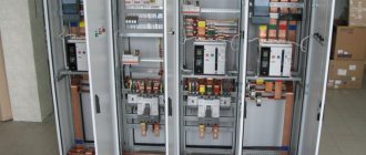
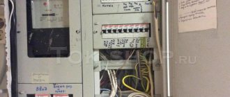
After receiving permission to connect to three phases and technical conditions, we will begin to independently assemble the shield. The input will be mounted in a sealed box, which must be assembled on the outer wall of a private house or pole. It contains a three-phase meter and a circuit breaker, as shown in the photo below:
Near the input we organize a grounding device, according to the rules. The input electricity metering panel will be sealed and there will be no free access to it. Therefore, the first thing you need to do is assemble a three-phase distribution panel yourself, distributing consumers as you wish.
A 5-core cable L1 is connected from the input box to the electrical distribution panel; L2; L3; N; PE, or 4-wire L1; L2; L3; N provided that the TN-CS grounding scheme is used or another grounding device is organized near the panel.
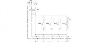
To connect three-phase home equipment, you will need to assemble a shield according to the following diagram:
The assembly of a 380-volt metering board is carried out with a stranded wire, with a cross-section of at least 4 mm and colored insulation. Recommended colors - L1 red, L2 white, L3 black, N blue, PE yellow-green. To correctly assemble a three-phase panel, you need to carefully look at the protective devices on which phase marks are marked for connecting the wires. This diagram shows four-pole RCD protective devices with an additional N terminal; in conventional machines this terminal may not be present. One by one, we begin to connect the devices installed in the panel on the DIN rail, measure the wire from terminal L1 to terminal L1 of the next device, with a margin of 30%, for ease of installation and operation.
We carry out this operation with all terminals, but keep in mind that it is not recommended to cut the sections in advance, because during the assembly process you will notice that the length of section L1 is much shorter than the mounting section L3. It’s even better to assemble the shield using a three-phase mounting bus, which will save space and minimize the chances of getting something mixed up. We separately install the zero bus and the PE bus, which we must connect to the housing of the electricity metering panel.
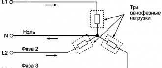
If you don’t have powerful equipment in your apartment or house, you need to assemble a 380V panel in such a way that each phase is evenly loaded with single-phase consumers. You can see an example of such an assembly of a three-phase electrical panel in a private house below:
In this electrical panel diagram, the phases are distributed to a separate load, through single-pole circuit breakers and differential switches. L1, L2 and L3 are evenly loaded by consumers, according to the previously calculated expected load.
It is not recommended to do this - one phase for sockets, another for lighting, a third for any other needs, because
it is important to distribute the load between L1, L2, L3. If one of the phases is overloaded, the voltage drops on it, while at the same time the voltage rises on the free ones
This phenomenon can often be observed in the winter, in the residential sector. If your neighbor in the phase turned on a powerful consumer, the lighting lamps in your house began to glow dimly, and the refrigerator began to hum strainedly. Know this is a drawdown in your phase. And at the same time, other neighbors’ lamps, powered from other phases, begin to glow brightly and explode, equipment burns out, and a fire may even break out.
As for the three-phase load, such a distortion will be fatal for it. To prevent this from happening, when you decide to assemble a shield, additionally install a phase and voltage control relay for a three-phase network. For a single-phase network, connect a voltage relay. You can check the load distribution using a multimeter with a current clamp, which is shown in the photo below.
Well, the last option for assembling a 380-volt electricity metering panel is mixed, when the home electrical network contains both three-phase and single-phase electricity consumers. In this case, you need to assemble the electrical panel as follows:
Assembly on differential automatics
Advantages:
- Each line is protected from short circuits, overloads, and leaks. And all this is just one device.
- It’s easier to identify the problem area in case of damage
- no zero buses
- you have complete freedom in grouping devices in the shield
- easy to distribute the load across phases
Flaws:
- large dimensions of the shield and a large number of modular devices (from 72 pieces or more)
- very expensive
A differential machine is equipment that is installed on a separate line, like a regular machine, but also includes leakage protection (differential protection).
Although this is the best option, it is also the most expensive. Therefore it is used extremely rarely.
The total amount of such an assembly can reach 200 thousand rubles.
Relatively speaking, how many outgoing group lines you have, the same number of differential automatic machines will be needed.
At the same time, in order to understand in case of possible accidents why such a machine has switched off, from a leak or a short circuit, it is recommended to use models with an indication of the cause of operation.
At the beginning of the circuit, an input device is mounted - a switch. From it you supply power to the voltage relay.
Next, through cross-modules you divide the load into diffs. You run one phase for each machine.
If it later turns out that one or another line overloads any of the phases, you just need to swap them on one of the cross-modules, transferring the wires from one busbar to another.
If you are not limited by budget, then this is the best option for assembling and completing a three-phase panel.
Electrical 380V electricity metering panel for a private house with a 220V socket
In this electrical panel diagram, there is additionally a modular 220V socket (number 7) with an individual protection device - difavtomat (number 8), which combines a circuit breaker and a residual current device. The rating of the RCD must be higher than that of the circuit breaker, for example 40A, leakage current 100 or 300 mA.
Electrical metering panel 380V, with modular socket and automatic circuit breaker, TT grounding
Following this example, where the outlet is protected by a residual current circuit breaker, you can install any other modular equipment, contactors, transformers, etc. to the electricity metering panel, if necessary.
Let me note again that under each diagram there are links, by clicking on which you can read the details, find out the equipment used, and ask questions.
Otherwise, here are the main options that are used when connecting private houses and garden houses to the power grid. And most importantly, such electrical panels are successfully accepted by regulatory authorities and put into operation.
Circuit breaker installation
The input machine (No3 in the diagram) is installed in the box . After connecting the conductors to it, it is closed with a lid.
Later, representatives of the energy sales company will seal it, install a seal and check it every time readings are taken or control rounds are taken.
For three-phase 380V networks, with an allocated power of 15 kW, the rating of the three-pole circuit breaker should be 25A.
A private house
A private house can have either a single-phase or three-phase electrical network. In the first case, the electrical installation diagram will be similar to the project for power supply of a one-room apartment. The simplest option for connecting a panel for a residential building will look like this:
In this diagram of a 220 V private house distribution board, there is a two-pole switch at the input, then an electric meter is connected, after it there is an RCD and a group of single-pole circuit breakers. Everything is quite simple and at the same time according to GOST. If a three-phase network is connected to your site, then the circuit diagram for assembling the panel will look different. Consumers from outbuildings - a garage, utility room or even a bathhouse - can already be added to it. The shield, of course, will be large and with many branches, so for the example we found a fairly suitable option.
Distribution board diagram of a private house for 380 V, using an RCD:
I would like to add a small description to this electrical circuit:
- A separate line is allocated for the garage power supply, protected by a residual current device. The remaining two machines are installed on a group of sockets and garage lighting.
- If there are three-phase electricity consumers in the house, it is better to connect them through a three-phase machine and a four-pole RCD, as shown in the example above. If there are no three-phase electrical appliances, you can use the project provided below.
The last 2 380 Volt distribution board schemes can be used not only to power an individual residential building, but also to power a spacious country cottage! We also recommend checking out the article on how to install electrical wiring in your home.
Hello. I want to install an electrician in a country house. On the pole there is a switchboard with a sealed 25 A machine, then a brush and again a 25 A machine. I want to install light in the house and assemble the panel. But now I don’t know what machines and RCDs to install at the entrance in the panel in the house. You have a 40 A automatic machine and a 40 A and 30 ma RCD. How will this fit with my 25A machines. And which wire to use, VVG 3x4 or 3x6?
Hello! It makes no sense to install machines in a house with a rating of more than 25 amperes; the VVG 3*4 cable has a good supply, so install it.
On one of your diagrams, after the meter there is an ouzo-d. At 20 amps. If I understand correctly, D is an ouzo category. This category is used for factories, workshops, etc. It is not recommended for apartments. since this category. Designed for high current loads at peak moment, that is. When starting engines. Until they work normally. Since when starting the engine consumes several times more current than during its normal operation
Electrical panel design and elements
Electrical panel elements
For a three-phase panel with a power of 15 kilowatts and a consumption power of 15 kW/h, the following components will be needed:
- Electricity metering device. The meter is installed in the panel immediately. Electronic models that are highly accurate and reliable are suitable for a home network. They work at several tariffs and display data on a digital display.
- Electrical panel It is a box of various sizes. The outdoor version must have a DIN rail, a lock, and an inspection hole for taking readings. The optimal level of dust and moisture protection is IP 54, wall thickness is 1 mm.
- Difavtomat at the input. A three-pole model connected to three phases is suitable.
- RCD. Element of protection against the occurrence of dangerous potential on the device body.
- Automatic type switch. In a private house, you will need a 25 A device for input, for a lighting system - 6.3 or 10 A, for a power circuit - 16 A. The power of such a switch is from 7 kilowatts.
- Voltage relay. Prevents damage to household equipment due to voltage fluctuations.
- Measuring devices. A voltmeter and an ammeter in one housing is an optional device.
To prevent pulse oscillations and protect against lightning, you can replace the relay with an SPD.
Selection of electrical installation equipment
Before starting installation, you need to buy the electrical panel itself and all the electrical installations and devices that will make up its contents. It should be taken into account that each item occupies a certain number of mounting spaces on a DIN rail - a metal strip 3.5 cm wide. One or several DIN rails can be located in one box.
One “mounting point” includes a section on the profile 1.75 cm long - a module. The passport of the electrical panel must indicate how many modules it is designed for.
Three devices are fixed on one DIN rail: the first two occupy 3 modules each, the third – one module. It is not recommended to leave spaces between adjacent devices to save space.
Before choosing a shield, you should add up the number of all modules, and then add to the resulting sum several places that may be useful in the future. As an example, let’s calculate which box is needed for a 1-room apartment.
Using the diagram, we determine how many modules each device occupies: 4-pole input circuit breaker - 4 spaces, counter - 6, RCBO - 2 x 2, circuit breakers - 4. The result is 18 modules
For 18-20 seats, an electrical panel with 24 modules is suitable. But if the apartment is large, and in the future you plan to purchase new equipment, install a heated floor, or make repairs with replacement wiring, then it is better to purchase a box with 36 seats.
If you want to simplify further work, maximize network protection, and make the arrangement of modules convenient, try to choose a panel with a complete set, and this is:
- removable frame with DIN rails;
- entry holes and holders for fastening cables;
- two tires, working and protective zero - with stands and installation sites;
- set of fastenings for installation;
- organizers for wires.
Shields can be metal or plastic, built-in or mounted.
Let's look at how they differ fundamentally.
Experienced electricians recommend working with one shop. The advantages of purchasing from a large supplier are a large assortment of goods and a guarantee of receiving original products and not counterfeits. Therefore, it is better to purchase both the shield and the rest of the electrical installation products in one place.
In addition to the metering device and protective devices, you will need:
- combs for several poles with end caps - to connect modules to each other, simplify installation and save space;
- 2-3 meters of PV1 wire with a cross-section similar to the input cable and color-coded insulation;
- zero busbars or cross-modules for group RCDs;
- clamps and ties for organizing conductors;
- limiters for DIN rails;
- plugs for masking empty spaces.
If financial capabilities allow, then it is better to select equipment from one trusted manufacturer - Hager, ABB, Legrand, Schneider Electric. Devices of the same brand are easier to install, and the shield will look much more aesthetically pleasing.
Design
The apartment panel in question meets the requirements for class II electrical equipment. The box-type control panel (Fig. 2 and 3) is designed for hidden installation in a niche on a vertical wall. The KShch body is a metal box with a single door measuring 1134x560x120 mm. It provides IP31 degree of protection.
Rice. 2. External view of the apartment panel with a closed (A) and open door (B) (based on Figure 6.17 from the book [1] by Yu.V. Kharechko)
The switchboard housing contains a mounting panel designed for installation of circuit breakers, differential current devices, terminal blocks, busbars and other electrical equipment. The panel covers are made of insulating material. They prevent access to live parts of the switchboard. The mounting panel is 500 mm wide.
Rice. 3. External view of the apartment panel with the panel covers removed (based on Figure 6.18 from the book [1] by Yu.V. Kharechko)
The upper part of the mounting panel KShch (Fig. 4) is used to make an input block and a distribution block. The following electrical equipment is installed on this part of the panel:
- input spring clamp blocks, which are designed to connect the phase, neutral and protective conductors of the electrical input circuit, as well as the internal electrical circuit of the control panel. These terminal blocks allow the connection of conductors with a cross-section of up to 16 mm2;
- input four-pole circuit breaker QF1 series S 200 with all protected poles, which has a rated current of 40 A, a rated short-circuit switching capacity of 6000 A and instantaneous tripping type C;
- four-pole circuit breaker QF2 series S 200 with all protected poles, which has a rated current of 16 A, rated short-circuit switching capacity of 6000 A, instantaneous tripping type C;
- four-pole SPD FV1–FV4 Type 2 with a maximum discharge current of 40 kA, rated discharge current of 20 kA, rated voltage of 230 V and protection voltage level of 1400 V;
- busbars L1, L2, L3 and N, made on the basis of a four-pole distribution block with a rated current of 125 A and allowing the connection of 10 conductors with a cross-section of up to 16 mm2 and 2 conductors with a cross-section of up to 35 mm2;
- PE protective busbar, which is part of the KSh busbars, which is made on the basis of a busbar that allows the connection of 4 conductors with a cross-section of up to 10 mm2 and 19 conductors with a cross-section of up to 4 mm2;
- four-pole VDT1 QF3 and QF7 type A, for general use, having a rated current of 40 A and a rated residual current of 0.03 A;
- two-pole circuit breakers QF4, QF5, QF6 series S 200 with all protected poles, which have a rated current of 10 A, a rated short-circuit switching capacity of 6000 A and instantaneous tripping type C;
- two-pole circuit breakers QF8, QF9, QF10 series S 200 with all protected poles, which have a rated current of 16 A, a rated short-circuit switching capacity of 6000 A and instantaneous tripping type C;
- three-pole spring terminal blocks for connecting phase, neutral and protective conductors with a cross-section of up to 4 mm2 of single-phase final electrical circuits (groups 1–6).
Rice.
4. The upper part of the control panel panel with the cover removed. The figure shows: 1 – input terminal blocks; 2 – automatic switch QF1; 3 – automatic switch QF2; 4 – busbars L1, L2, L3, N; 5 – VDT QF20; 6 – PE protective busbar; 7 – SPD FV1–FV4; 8 – VDT QF11; 9 – VDT QF7; 10 – automatic switches QF8, QF9 and QF10; 11 – VDT QF3; 12 – automatic switches QF4, QF5 and QF6; 13 – three-pole terminal blocks for connecting conductors of single-phase electrical circuits (group 1–6) (based on Figure 6.19 from the book [1] by author Yu.V. Kharechko) The lower part of the switchboard mounting panel is used to make a distribution block (Figure 5) . The following electrical equipment is installed on this panel:
- four-pole RCCBs QF11, QF15, QF20, QF27 and QF29 type A, for general use, having a rated current of 40 A and a rated residual current of 0.03 A;
- four-pole circuit breakers QF26 and QF28 series S 200 with all protected poles, which have a rated current of 16 A, rated short-circuit switching capacity of 6000 A, instantaneous tripping type C;
- two-pole circuit breakers QF12–QF14, QF16–QF18, QF19, QF21 and QF22 of the S 200 series with all protected poles, which have a rated current of 16 A, a rated short-circuit switching capacity of 6000 A, instantaneous tripping type C;
- two-pole RCBOs QF23, QF24 and QF25 series DS 941 type A, for general use, having a rated current of 16 A, rated residual current of 0.03 A, rated short-circuit switching capacity of 4500 A, instantaneous tripping type C;
- three-pole spring terminal blocks for connecting phase, neutral and protective conductors with a cross-section of up to 4 mm2 of single-phase group electrical circuits (group 7–18);
- five-pole spring terminal blocks for connecting phase, neutral and protective conductors with a cross-section of up to 4 mm2 of three-phase group electrical circuits (groups 19 and 20).
Rice.
5. The lower part of the housing panel with the cover removed. The figure shows: 1 – RCCB QF27; 2 – VDT QF20; 3 – automatic switches QF19, QF21 and QF22; 4 – VDT QF15; 5 – VDT QF11; 6 – automatic switches QF12, QF13 and QF14; 7 – RCBOs QF23, QF24 and QF25; 8 – automatic switch QF26; 9 and 10 – three-pole terminal blocks for connecting conductors of single-phase electrical circuits (groups 13–18 and 7–12); 11 – VDT QF29; 12 – automatic switch QF28; 13 and 14 – five-pole terminal blocks for connecting conductors of three-phase electrical circuits (groups 19 and 20) (based on Figure 6.20 from the book [1] by Yu.V. Kharechko) Input terminal blocks intended for connecting phase conductors are gray in color , neutral conductors – blue, protective conductors – yellow-green. The terminal blocks for phase conductors and neutral conductors are connected in pairs using two jumpers.
Automatic switches QF1 and QF2 are connected to the phase and neutral input blocks of the KShch terminals. The QF1 circuit breaker is connected to busbars, which include three phase busbars (L1, L2, L3) and a neutral busbar (N), and the QF2 circuit breaker is connected to a four-pole SPD FV1–FV4.
The internal electrical circuits of the switchgear from the input terminal blocks to the busbars (including the PE protective busbar) and from the busbars to four-pole RCCBs are made of insulated flexible copper conductors with a cross-section of 10 mm2. The remaining electrical circuits inside the switchboard up to the terminal blocks intended for connecting the conductors of the final electrical circuits are made of insulated flexible copper conductors with a cross-section of 4 mm2.
For every three two-pole circuit breakers connected to one four-pole RCCB, the input (upper) terminals of the poles to which the neutral conductors must be connected are connected to each other by a connecting bus with blue insulation. This connection bar is a PS1/57NA type connection bar cut into pieces containing five pins, two of which have been removed. It is used to make an electrical circuit of a neutral conductor. The output (lower) terminal of the switching neutral pole of a four-pole RCCB is connected via a neutral conductor to one of the specified input terminals of two-pole circuit breakers.
Metal mounting rails of the control panel, on which the terminal blocks are installed, are used as protective conductors. The input protective terminal block forms electrical contact with the mounting rail. All terminal blocks intended for connecting protective conductors of final electrical circuits also form electrical contacts with mounting rails. By means of the specified terminal blocks and the mounting rails on which they are installed, internal electrical circuits of protective conductors are formed in the control panel. These mounting rails are secured to the mounting frame using special insulators, which prevent their electrical connection with other metal elements of the control panel mounting panel. These mounting rails are connected by protective conductors to the protective busbar of the control panel, which is connected by a protective conductor to one of the terminals of the input protective terminal block.
Features of the electrical panel
Often home renovations need to be combined with electrical wiring repairs. If you do it with a large margin of safety, then this may ultimately cause a fire.
If, on the contrary, you make it unbearable to loads, then the plugs on the electrical panel in a private house will have to be constantly changed. Therefore, both the shield and the wiring must be carefully calculated for the current and voltage.
What is current strength
Any electrical appliance has an indicator indicating current and power consumption. If there are no current values on it, but only power consumption and voltage, then you need to divide the power by the voltage value.
When calculating the electrical panel in a private house, it is necessary to take into account the current strength. The maximum current value in an apartment is determined as the sum of the power consumption of all switched on devices, divided by a voltage of 220 Volts. If the wiring is designed for low current, then with a small load they can burn out.
It is necessary to calculate not the nominal, but the peak load, because in any apartment sometimes a vacuum cleaner or iron is turned on. So, for example, if a computer of 400 W, a lamp of 100 W, a table lamp of 75 W, a TV of 150 W, as well as a “stray load” of a heater of 2 kW, a vacuum cleaner of 1.8 kW, are constantly turned on in a room, then the peak consumption of the room will be 5.5 kW or 25 amperes.
What is the shield for?
Many home owners do not know what an electrical panel is for. Its main purpose is to protect against network overloads that can cause a fire.
If the wiring has a low cross-section, then under heavy loads it may not withstand and catch fire. If there are oversized circuit breakers on the electrical panel, then if high-power appliances are turned on in the house for a long time, the sockets may burn out.
If you increase the cross-section of the wiring, then the apartment, in fact, will also be left without protection: the machines may not respond to high load parameters. In a word, the shield must have optimally selected plugs, which must match both the power consumption and the cross-section of the wiring.
What types of wires are there?
Standard wires are connected to the panel. Copper wiring has four standard types of cross-section - from 1.5 mm 2 to 6 mm 2. The permissible current strength of the thinnest wire is 15 amperes, the thickest is 34 amperes. The aluminum wire must have a much larger cross-section. It is not recommended to use soft cables, as there may be problems with the safety of the wiring.
Be careful: shields in a private house and sockets are not suitable for wires smaller than one and a half square meters. mm. There is also no need to take machines smaller than 10 amperes.
What needs to be installed in the panel
The panel must provide for the division of wiring into several lines. If there is one line in the house, then in the event of an accident the entire house will be de-energized. By dividing the wiring into several parts, it will be easier to determine the location of the accident.
Several circuit breakers need to be installed in an electrical panel in a private home. For example, for each room you need to install a separate machine. Ideally, there would also be an automatic for lighting. The machines receive power through one large machine. This is necessary so that you can quickly turn off the power to the entire room. The machine is numbered in position from left to right.
Installation and replacement of the shield
You can install the electrical panel yourself. The simplest procedure in this case is to replace the machines.
The meter can be seen on the panel, as well as a batch switch and automatic machines. The batch switch looks like a device with four contacts and a rotary handle. From the main electrical wires, phase and zero come to the panel.
Before replacing machines, you need to check their nominal value and buy the same one. In no case should you install a machine with a larger rating, as this leads to accidents if many powerful devices are turned on simultaneously on one machine.
Replacing the machines is done with the package switch completely turned off. However, you need to be careful, otherwise if you move incorrectly you can be left without light. Remember that you cannot repair or install a packet switch yourself. To do this, you need to call a qualified electrician.
If a short circuit occurs when installing machines, you need to check the condition of the wire insulation and, if necessary, replace it with electrical tape.
Plastic enclosures for the electrical panel can be purchased at the store. As a rule, they have a ready-made DIN rail. The product package also includes grounding pads and a zero. You should not buy cases with plastic slats, as they break and do not provide the necessary safety.
(No votes yet)
No comments yet!
Improving the budget scheme
Now let’s take a closer look at the option with two-pole circuit breakers, which was preferred by the customer. Its price is about 90 thousand rubles, versus 80 thousand for a shield on single-pole networks. And two-terminal networks give us nothing more or less than that same zero pole for each line. And this will make it possible to quickly put into operation all the lines under the triggered RCD, except for the problematic one, including in the case of a leak from scratch.
By disconnecting the problem line with a two-terminal device, we localize the problem within the boundaries of this problem line. The remaining lines remain in operation. Well, yes. Everyone has their own zero. And the problematic one is now disabled. The procedure for localization is similar to what I described just above for single-pole networks. Yes, you have to pay for this opportunity. At today's prices, this is about 650 rubles for each line minus the cost of zero buses, which are not needed in a circuit with two-terminal networks.
In some cases, you will have to use a box of a larger standard size than in the version with single-pole circuit breakers. But in this case, with 17 groups, both options on automatic machines required the same box for 72 modules as with two-terminal networks. The lion's share of the space in the box (60%) in this scheme is occupied by switches, RCDs, UZMs, cross-modules and a non-switchable group. And there’s no way to fit three groups of machines onto half a DIN rail, even with 18 modules. But in the version with single-pole circuits, you can safely add another 4-pole RCD with a group of five circuit breakers to this box.
Assembly diagram of a distribution panel in an apartment and a private house
16.06.2015 7
In order for the electrical wiring to be safe, easy to maintain, and also able to withstand the load from all electrical appliances in the home, it is necessary to correctly approach the design of the distribution board wiring diagram. This project should indicate the entire hierarchy of circuit breakers and RCDs, right down to the socket group. In addition, all protective automatic devices must indicate the rating, as well as the protection class. Next, we will provide readers of the Sam Electric website with visual diagrams of the switchboard in a private house, apartment and cottage.
So, if the apartment is of old construction and, moreover, one-room (for example, Khrushchev), then the electrical wiring project will look like this:
As you can see, in this wiring diagram for the distribution panel there is no PE bus, because In old Khrushchev buildings there is no grounding. As for the elements of the electrical circuit, it consists of a two-pole circuit breaker, an electricity meter (Mercury 201), an RCD and group “packets”. One machine serves the lighting group, the second - sockets, and the third - the washing machine. If you have a ground loop, then the electrical diagram for assembling the distribution board in the apartment will look like this:
The dotted line (1) indicates the housing of the distribution board, (2) and (3) this is the neutral and grounding bus. The fourth element of the project is the comb that connects the circuit breakers. (5) - a single-phase RCD of 40 Amperes and a leakage current of 30 mA, and (6) - group circuit breakers (3 of 16 Amperes and 1 of 25, for connecting a hob). A single-pole circuit breaker with a rating of 40 Amps is installed at the input. The lowest row of the electrical circuit consists of residential consumers - a group of lighting, sockets and powerful electrical appliances (in our case, stoves).
Well, there are also spacious apartments with electric heating and a group of powerful electricity consumers. In this case, the electrical circuit of the input distribution panel will be more serious and the number of circuit breakers will be no less than that of a private house. So, for your attention, the distribution board diagram for an apartment with an improved layout:
With such a number of electricity consumers, there must be a three-phase network (380V) and at the input, accordingly, a three-pole 63 Ampere circuit breaker. Otherwise, there is a 40 Ampere RCD, a group of 16 and 25 Ampere circuit breakers (depending on the purpose), and a separate residual current device for electrical wiring in the bathroom. with a leakage current of 10 mA.
Based on the provided apartment panel connection diagrams, design your own version and proceed to electrical installation work! How to assemble a switchboard with your own hands. we already told you!
Outgoing line machine
On the Internet, I came across the opinion that you can get by with a switch, they say, the input machine also protects the outgoing line. However, at that time, when coordination of schemes was mandatory, I was directly required to put the machine on the outgoing line. Although in my practice there have been cases when a network company accepted boxes with metering units where a switch was installed. But this was only one such network company. Everyone else demanded a machine gun. By the way, here you can learn about choosing a machine.
Switchboard layout
I have already discussed in detail the basic principles of layout when designing and assembling distribution boards. In the electrical panel under consideration, the layout (i.e., the arrangement of devices inside the electrical panel itself) is adopted in a row in groups.
Enter
A load switch and a voltage control relay are installed on the first DIN rail at the input of the distribution board.
The load switch allows, if necessary, to completely de-energize the entire electrical panel for repair or maintenance work on both the switchboard and the entire apartment electrical wiring as a whole.
The ZUBR voltage control relay provides protection of the home electrical network from surges and surges in voltage in the supply network, as well as protection from zero loss.
Later, depending on financial capabilities and the purchase of equipment for a low-current network, the customer will add here both a circuit breaker for a low-current switchboard and other devices that are still being considered.
Kitchen
A group kitchen RCD is installed on the second DIN rail, and after it there are automatic switches for kitchen consumers:
— electric oven;
- kitchen sockets;
- kitchen air conditioner.
Room sockets
A group RCD of socket groups is mounted on the third DIN rail, followed by automatic switches in the rooms:
- room sockets;
— two air conditioners;
- apartment lighting.
Doubtful ideas sometimes shoot out
Well, one more, fourth option. At first glance, it may seem dubious and unreasonable. Upon closer examination, it turns out to be quite viable and allows you to get the functionality of a shield on automatic machines for significantly less money. The point is to provide each line with its own protection against leakage currents, i.e. A 2-pole RCD in addition to a single-pole circuit breaker. This personal protection will take 3 modules on a DIN rail for each line, i.e. you will need one and a half times more space in the box than for difautomatic machines, but each line will receive its own two poles - zero and phase and, more importantly, its own protection against leakage currents.
If we take into account that we do not need bulky 4-pole RCDs as in other alternatives, and it is quite possible to get by with one 4x7 cross-module to distribute power across phases, then the proposed circuit fits quite easily into the same 4x18 box. And there's still room left.
Now for the price. A type A differential with a nominal value of 16A costs 5.3 thousand rubles today. A combination of RCD A25/0.03 + automatic C16 will cost 3.5 thousand. Those. we will also save 1800 rubles on each line. Thus, the scheme, which was dubious at first glance, turned out to be similar in functionality to the scheme on difavtomats with a shield price of about 114 thousand rubles.
Electric installation work
We will not dwell in more detail on the preparation of documentation for connecting the power supply; this is a separate topic. Our task is to determine the materials and devices for external installation work, which, although they are an intermediate stage in the connection, are the most important, since they are related to human safety.
Single-phase or three-phase input?
For both three-phase and single-phase networks, the permitted power is indicated in the technical specifications. This can be 15 kW for both options, that is, the benefit of a three-phase network is not in power, but in the possibility of using an input cable of a smaller cross-section and reducing the load, since the current is distributed over 3 phases. Therefore, in a three-phase network, the rating of the input circuit breaker will be lower.
But the input distribution board will be increased in size, since the meter itself is larger than a single-phase one, and the circuit breakers occupy 3-4 modules. Three-phase RCDs also have larger dimensions. This is a disadvantage of three-phase input into the house, but it is not very significant compared to such advantages as the ability to connect asynchronous electric drives, electric boilers, heaters, and electric stoves in the house.
To avoid phase imbalance from powerful electrical receivers, the electrician-installer must distribute the load as evenly as possible. The operating voltage of a three-phase network is 380V, therefore, in order to eliminate the risk of fire and electric shock, it would be a good idea to install a three-pole additional circuit breaker right before entering the house. This prevents short circuits at the input.
Read also: Equipment for surveillance and wiretapping
External connection and electrical panel
When connecting a private house to the power supply, an air input is most often used (which is also indicated in the technical specifications) with the installation of an electricity metering cabinet (SHUE) to eliminate cases of electricity theft and problems with the commercial registration of electricity supply.
According to the standards, the input cable must have a cross-section of at least 16 mm2 if the core is aluminum, and 10 mm2 if the core is copper, at a distance from the support pole of 25 m. For a distance of less than 25 m, the cross-section of the aluminum wire is 10 mm2, copper - 4 mm2 .
If you have decided on the method of connection from the pole to the house (aerial or underground), as well as the type and cross-section of the cable, then it remains to figure out exactly how the wire is connected to the house, from where further wiring to the devices is made.
The wire cross-section is selected according to the PUE based on the long-term permissible current. For aerial input, the most common cable is VVG or VVGng (modern version), as well as cable AVVG and SIP (self-supporting wire). By the way, for underground input, VBBbShv or AVBbShv cable is most often used. As you already understand, the presence or absence of the letter “A” means an aluminum core.
The value of the cable cross-section and the long-term permissible current for it are taken from the PUE. The optimal cross-sections for the input cable are 10, 16, 25 mm2, with a maximum permissible current, respectively: 50, 70, 85A (for underground input), and 80, 100, 140A for air input. For example, to a copper wire with a cross-section of 10 mm2, you can connect a power of 15 kW for a voltage of 230 V and from 30 kW for a voltage of 380 V.
If your main grounding bus is located on a pole and not in a cabinet, then the cable from the pole should be five-core (for example, VVG5 x 4.0) - three phases, a working zero (N) and a protective zero (PE).
High-quality cable products are produced domestically, Sevkabel, Concord, Nexans.
The entry point into the house should be located at a height of 2.75 m. It happens that the height of the house is not enough, then a special pipe stand, straight or curved (gander), is installed in the hole in the roof or wall. If the house is high, then the distribution cabinet with an RCD is mounted on the wall, where the cable is led from the pole.
According to the rules, the distance from the pole to the house should be less than 25 m, so as not to install additional support. The electricity metering and distribution cabinet provides all the devices necessary for protection, metering and further distribution of electricity in the house:
- input device - automatic or switch type RPS;
- electric meter (electronic or induction);
- residual current device (RCD);
- a number of circuit breakers protecting the network from short-circuit currents and overloads. Here you can also use DIFs - (differential circuit breakers).
An input circuit breaker or switch is included in the circuit in front of the meter for possible disconnection of all phases of the supply voltage. This is done so that the meter can be replaced safely.
For commercial electricity metering, a meter is installed in the cabinet. If necessary, you choose an electricity meter for a single-phase network (220/230V) or three-phase (220/380V), single-tariff or multi-tariff. With an supplied power of 15 kW, it is enough for the maximum load current of the meter to be in the range of 50-60A. This corresponds to the rating of the input circuit breaker no more than 40A. Models of modern meters: "Mercury" 200.02 220V 5(50)A - designed for single-phase circuits, "Mercury" 230 ART-03 5(7.5)A - for three-phase.
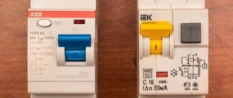
An RCD protects a person from electric shock, and a house from a fire, therefore, it is imperative to install it in the electrical panel. Instead of an RCD, you can use a differential circuit breaker.
| 1 | Introductory machine |
| 2 | Counter |
| 3 | Fire protection RCD |
| 4 | Common zero bus |
| 5 | Lighting machines |
| 6 | RCD for consumers 2, 3, 4 |
| 7 | Vending machines for consumers 2, 3, 4 |
| 8 | Additional zero bus |
| 9 | Differential automatic |
| 10 | RCD for consumers 5, 6, 7 |
| 11 | Vending machines for consumers 5, 6, 7 |
| 12 | Additional zero bus |
| 13 | Ground bus |
In our electrical networks, there are frequent surges and surges in voltage, from which a voltage stabilizer . It smooths out fluctuations by supplying 220V to the output. When the voltage drops below 160V, or when it increases above 280V, the stabilizer is usually disconnected from the external network and de-energizes consumer devices, protecting them from damage. Audio and video equipment, as well as light bulbs, are especially sensitive to surges, as they flicker and their service life is reduced.
The dimensions of the stabilizer depend on the power of the connected load, therefore, they can be bulky and require a lot of space for placement, while there must be space on all sides of the stabilizer so that it can be cooled by air.
In three-phase networks, a different stabilizer is used for each phase. Their prices are quite high, they are much more expensive than devices such as voltage control relays , which are also called “barriers”. Advantages of the relay: small dimensions, affordable cost, installation in a panel on a 35 mm DIN rail. VP-40A 220V DigiTOP voltage control relay with digital control is very convenient to use .
In conclusion, I would like to once again draw your attention to the fact that all work on connecting a power of 15 kW to a private house must be carried out by the organization that is responsible for the electrical equipment of the area, sending trained specialists.