How smartphone chargers work
There are a lot of companies that make chargers, and you can specifically choose one that suits your gadget or choose a universal one. The country of assembly also does not particularly affect its performance, it is only generally accepted that the “original” models are more durable. But it all depends on the operating conditions.
The basic operating principle of chargers is the same for all: it contains a blocking generator, which rectifies the current using a transformer.
To clearly see how the charger works, follow the link and watch the video
Principle of operation
Almost all circuits that can be used to assemble regulated power supplies for output voltage contain simple and easily accessible parts. The operating principle of the device is as follows:
- the regulated power supply is plugged into the outlet using a two-pole plug XP1;
- when switch SA1 is turned on in a 220 V network, current is supplied to the primary winding;
- when the voltage is turned off, the current is supplied to the step-down transformer T1 (to its primary winding - a);
- the transformer reduces the mains voltage to 14–17 volts. It is removed from the b-winding (secondary, II) of this part;
- then it is rectified by diodes VD1 - VD4. These diodes are connected in a bridge circuit. As a result, the voltage is smoothed by filter capacitor C1. Without this capacitor, during operation of the receiver/amplifier, hum generated by alternating current will be heard through the speaker;
- The capacitor and diodes VD1 - VD4 together form a rectifier. From its input, a constant voltage is supplied to the input of the stabilizer. This stabilizer consists of R1, VD5, VT1; R2, VD6, R3; VT2, VT3, R4;
- Zener diode VD6 and resistor R2 form a parametric stabilizer. It stabilizes with variable resistor R3. This resistor is connected in parallel with the zener diode. With its help, the voltage at the output of the power supply is set.
Advantages and disadvantages of homemade charging
The undoubted convenience and pride from the fact that you managed to assemble a new charger for your phone literally “on your knee” is gradually giving way to wariness about whether you did everything correctly and whether you will thereby cause irreparable damage to your gadget. After all, those chargers that are created for a specific phone model have the appropriate characteristics and are safe to use.
Incorrectly configured devices can output the wrong voltage and, one way or another, ruin the operation of the gadget itself.
However, if you did everything correctly, then for some time you will be able to get by with your homemade charger. And having such a homemade charger is always convenient. You can put it in your hiking backpack or take it to your dacha where there are power outages.
In any case, any invention has its pros and cons.
Advantages and disadvantages
All parts are cheaper than a purchased branded phone charger
Most work without being connected to an outlet, and therefore are not tied to electricity
Can be carried with you
Charging speed will be slower compared to using a regular battery
If the contacts are connected incorrectly or weakly, you can cause injury to yourself or damage the phone itself.
Classification of power supplies
The difference in the principle of operation of the nodes allows us to classify them into:
- Pulse – inverter systems that convert alternating current into direct voltage of high frequencies.
- Transformer, consisting of step-down transformers and rectifiers. Their function is to convert variable power into constant power. In addition, capacitor filters serve to smooth out excessive oscillations and pulsations of functioning devices.
Power supplies containing quenching capacitors. They are similar to transformer power supplies, only the role of the transformer in this unit is performed by non-polar high-voltage capacitors.
Expert opinion
It-Technology, Electrical power and electronics specialist
Ask questions to the “Specialist for modernization of energy generation systems”
Power Supplies | Do it yourself The 1.5KE10 CA suppressor has the letter C in the name and is bidirectional; the polarity of installing it in the circuit does not matter. Ask, I'm in touch!
How to make a standard wired charger with your own hands
There are several options for what materials your charger will be made of. You choose based on what you have and which option appeals to you personally.
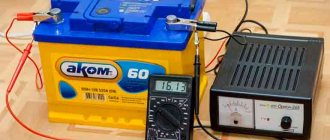
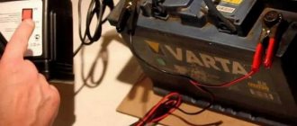
Battery charging
Very often, batteries or rechargeable batteries are used to create a portable charger. This is convenient; they can be replaced when they fail with new ones. In addition, such a device can replace a failed adapter, which is usually plugged into an outlet.
To create such a charge you will need:
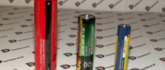
- AA batteries/accumulators;
- compartment;
- a working USB cable suitable for your phone;
- the charger itself (can be used from an old gadget);
- soldering iron and related equipment;
- tester;
- glue.
Now let's move on to creating the charger.
- Insert four batteries into the battery compartment (can be removed from a non-working children's toy or any other device). You need to check the total voltage. For this we use a tester. Phones are charged at a voltage of 5 Volts, and the voltage generated should not exceed it.
- We separate the plug from the USB cable that should be connected to the computer, remove all the wires except the “plus” and “minus” (for this we call the tester). The remaining wires need to be cut off, and the remaining wires must be fastened using a thermo-cambric and a lighter.
- We solder wires to metal rivets using soldering acid, and tinned the rivets. Make sure the charges match!
- The connector itself is now attached to the body using heated glue. To prevent breaks, we apply glue around it, closing all the contacts.
- We also cut off a smaller connector from the USB cable. Of the wires, we leave only the “plus” and “minus”, and cut off the rest. It is better to remove the remaining wires to the thermal cambric.
- Let's put everything together.
After this you can charge your phone.
Instead of batteries, it is preferable to use rechargeable batteries - and this is a big savings and longer service life - the batteries can always be recharged and used again.
Charging from fan and magnets
This is practically a free energy generator created by you. To create such a charge you need:
- neodymium thin magnets;
- fan from the system unit;
- glue;
- a cord with an input suitable for your phone;
- soldering iron and related equipment.
Let's look at the assembly in detail.
- We glue magnets to the fan blades using glue. The magnets need to be chosen thin enough so that they do not extend beyond the blades in width and not too much in height.
- One of the magnets needs to be glued to the corner of the fan (not from the corner where the wires come out).
- We cut the cable suitable for the telephone so that there remains a part that fits into the telephone socket with the desired length of the wire itself. We solder the wires from the fan to the phone wires, observing the polarity.
- It is better to hide the soldering area in a thermal cambric so that it does not get damaged and lasts longer.
- We attach three magnets on the opposite side of the first attached magnet to the fan. If the location is chosen correctly, the fan will start working the moment they are attached. If this does not happen, you need to move them, finding the desired position.
Now you can connect the gadget. If everything is assembled correctly, it will immediately begin charging.
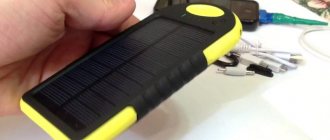
How to make a portable charger with your own hands
Wireless charging has even greater capabilities. USB cables may stop working, break, or break. And then the charging process becomes problematic again.
The principle of operation is based on the transfer of current from a coil that creates a magnetic field inside the charger to a coil in the phone that is the receiver. As soon as the receiver itself is within the coverage area of the conductor, pulses of electromagnetic waves begin to be transmitted from device to device.
Of course, with all its convenience, there are also negative aspects of such charging:
- Frequent use of wireless charging can negatively affect the phone's battery capacity;
- lack of any official studies on the effects on humans and animals;
- the time it takes to fully charge a mobile phone battery will be longer than with conventional wired charging;
- you cannot use the phone while it is charging - if you take it from the stand, the process will be interrupted;
- if something is done incorrectly, for example, the wrong power is selected, then the gadget’s battery may become unusable;
- Often, when using wireless charging, the back cover of the phone overheats greatly, which negatively affects the life of the gadget and its performance.
The situation can be complicated by the fact that not all models support wireless charging. In this case, you will have to make not only a transmitter, but also a receiver that fits under the phone body. However, if the phone has such a function, then there should be no problems.
Devices for wireless charging are not cheap. But you can always make them yourself.
For this you will need:
- copper wire, diameter 1 mm (several meters, 25 turns);
- frame (5-7 cm);
- glue;
- soldering iron and related equipment;
- capacitor;
- 10 Ohm and 1 K resistor (2 pcs);
- transistor;
- mobile phone charger to power the transmitter.
So, let's start assembling a wireless phone charger.
- The copper wire needs to be wound in a spiral; you only need to make 25 turns. From the start of unwinding, leave a tail 5 cm long (we consider it a “plus”).
- During the wrapping process, lubricate the spiral with glue so that it holds its shape. At the end of the process, let it dry. Glue can be replaced with varnish.
- Assembling the pulse generator. We do everything according to the plan.
- We connect the coil.
The finished transmitter can be placed in any housing; it is only important that the walls are thin and do not interfere with the transmission of pulses.
If your phone model does not support wireless charging, then the next step is to fix it.
To do this you need to use:
- capacitors for 10n, 100n and 10u;
- diode;
- Voltage regulator;
- wire 30 turns, diameter 0.4 mm;
- soldering iron;
- glue.
We also begin assembly by winding the wire into a reel. Now there should be 30 turns. They also need to be lubricated with glue or varnish during the process to secure them. Then we assemble the receiver itself, focusing on the diagram below.
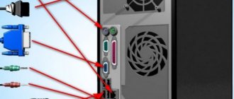
Next, you need to place the resulting receiver in the phone body and solder “+” and “-” to the corresponding connector wires to enable charging in the phone. It is important to do this very carefully so as not to damage anything. The branching of wires in gadgets can be seen in the picture below. Pay attention to the leftmost and rightmost wiring.
When everything is ready, you need to connect your made transmitter to the network and bring the phone as close to it as possible. The voltage and, accordingly, the charging speed depend on this.
When you place your phone within range of the battery you created, it should begin charging. You don’t need to connect anything separately and you don’t need to make any settings on your phone. If nothing works, then most likely you connected the wires poorly somewhere. Therefore, it is recommended to check the operation of devices before placing them under enclosures.
Another way to create a wireless charger with your own hands is presented in the video
High reliability circuit
Considering the circuits of Chinese chargers for mobile phones , one cannot help but mention the option of increased reliability. In this case, the input voltage becomes direct due to the use of a special diode bridge called VD1.
Additionally you will need:
- capacitor C1;
- resistor.
The power of the latter should not be less than 0.5 W. If the indicator is not the same as recommended by experts, then when you turn on the smartphone, the resistor will burn out. To limit the current in this circuit, a special emitter with a sensor is used.