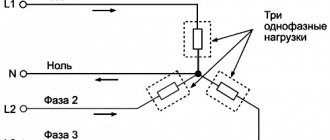
Three-phase load connected in star connection
If the loads (receivers) are connected in a three-phase circuit according to the “star” circuit (Fig. 1), then phase voltages are applied to the load resistances. Linear currents are equal to phase currents and are determined by Ohm’s law:
and the current in the neutral is equal to the vector sum of these currents: I N
=
I A
+
I B
+
I C
.
Fig.1
At symmetrical voltages UA
,
UB
,
UC
and the same resistances
RA
=
RB
=
RC
=
R
the currents
IA
,
IB
,
IC
are also symmetrical and their vector sum (
IN
) is zero. Then
IL =
IФ
=
UФ ¤ R
;
IN
= 0.
If the load phase resistances are not the same, then some current IN
No. 0. This is illustrated in vector diagrams (Fig. 2).
Fig.2.
The power of a three-phase load is the sum of the phase powers: S P =
PA + PV + PC.
When the load is symmetrical and purely resistive, we have
S P = 3
PF
=
3 UФ × IФ
.
With a mixed (active-inductive or active-capacitive) load:
Active power
S P = 3
× UФ × IФ × cos j = Ö3 × UL × IL × cos j
.
Reactive power
S Q = 3
× UФ × IФ × sin j
=
Ö3 × UL × IL × sin j
.
Full power
S S = 3
× UФ IФ = Ö3 × UЛ × IЛ
.
Calculation of a three-phase circuit connected by a star
Triangle connection. Scheme, definitions
Star connection. Scheme, definitions
If the ends of all phases of the generator are connected into a common node, and the beginnings of the phases are connected to a load that forms a three-pointed star of resistance, you will get a three-phase circuit connected by a star. In this case, the three return wires merge into one, called zero or neutral. A three-phase circuit connected by a star is shown in Fig. 7. 1.
Rice. 7.1
The wires going from the source to the load are called linear wires, the wire connecting the neutral points of the source N and the receiver N' is called the neutral (zero) wire.
The voltages between the beginnings of phases or between linear wires are called linear voltages. The voltages between the beginning and end of a phase or between the line and neutral wires are called phase voltages.
Currents in the phases of the receiver or source are called phase currents, currents in linear wires are called linear currents. Since the linear wires are connected in series with the phases of the source and receiver, the linear currents when connected by a star are simultaneously phase currents.
Iл = Iф.
ZN is the resistance of the neutral wire.
Linear voltages are equal to the geometric differences of the corresponding phase voltages
(7.1)
In Fig. Figure 7.2 shows a vector diagram of phase and line voltages of a symmetrical source.
Rice. 7.2
From the vector diagram it can be seen that
With a symmetrical system of EMF source, the linear voltage is √3 times greater than the phase voltage.
Ul = √3 Uph
If the end of each phase of the generator winding is connected to the beginning of the next phase, a delta connection is formed. Three line wires leading to the load are connected to the winding connection points. In Fig. Figure 7.3 shows a three-phase circuit connected by a delta. As can be seen from Fig. 7.3, in a three-phase circuit connected by a triangle, the phase and line voltages are the same.
Ul = Uф
IA, IB, IC - linear currents;
Iab, Ibc, Ica - phase currents.
Linear and phase load currents are related to each other by Kirchhoff’s first law for nodes a, b, c.
Rice. 7.3
The line current is equal to the geometric difference of the corresponding phase currents. In Fig. Figure 7.4 shows a vector diagram of a three-phase circuit connected by a triangle with a symmetrical load. The load is symmetrical if the phase resistances are the same. The vectors of phase currents coincide in direction with the vectors of the corresponding phase voltages, since the load consists of active resistances.
Rice. 7.4
From the vector diagram it can be seen that
,
Il = √3 Iph with symmetrical load.
Three-phase star-connected circuits have become more common than three-phase delta-connected circuits. This is explained by the fact that, firstly, in a circuit connected by a star, two voltages can be obtained: linear and phase. Secondly, if the phases of the winding of an electric machine connected by a delta are under unequal conditions, additional currents appear in the winding, loading it. Such currents are absent in the phases of an electric machine connected in a star configuration. Therefore, in practice, they avoid connecting the windings of three-phase electrical machines in a triangle.
A three-phase circuit connected by a star is most conveniently calculated by the two-node method. In Fig. Figure 7.5 shows a three-phase circuit with a star connection. In general, the load phase resistances are not the same (ZA ≠ ZB ≠ ZC)
The neutral wire has a finite resistance ZN. In a circuit, a nodal voltage or neutral bias voltage occurs between the neutral points of the source and load. This voltage is determined by formula (7.2).
Fig.7.5
(7.2)
Phase currents are determined by the formulas (in accordance with Ohm’s law for the active branch):
(7.3)
Neutral current
(7.4)
Special cases.
1. Symmetrical load. The load phase resistances are the same and equal to a certain active resistance ZA = ZB = ZC = R. Nodal voltage
,
because the three-phase EMF system is symmetrical, .
The load and generator phase voltages are the same:
Phase currents are identical in magnitude and are in phase with their phase voltages. There is no current in the neutral wire
In a three-phase star-connected system, with a symmetrical load, the neutral wire is not needed.
In Fig. Figure 7.6 shows a vector diagram of a three-phase circuit for a symmetrical load.
2. The load is asymmetrical, RA< RB = RC, but the neutral wire resistance is zero: ZN = 0. Neutral bias voltage
rice. 7.6
The phase voltages of the load and generator are the same
Phase currents are determined by the formulas
The current vector in the neutral wire is equal to the geometric sum of the phase current vectors.
In Fig. Figure 7.7 shows a vector diagram of a three-phase circuit connected by a star, with a neutral wire having zero resistance, the load of which is active resistances of unequal magnitude.
Rice. 7.7
3. The load is asymmetrical, RA< RB = RC, there is no neutral wire,
The neutral bias voltage appears in the circuit, calculated by the formula:
The generator's phase voltage system remains symmetrical. This is explained by the fact that the source of three-phase EMF has an almost infinitely large power. Load asymmetry does not affect the generator voltage system. Due to the neutral bias voltage, the load phase voltages become unequal. The phase voltages of the generator and the load are different from each other. In the absence of a neutral wire, the geometric sum of the phase currents is zero.
In Fig. Figure 7.8 shows a vector diagram of a three-phase circuit with an asymmetrical load and a broken neutral wire. The phase current vectors coincide in direction with the vectors of the corresponding phase load voltages. A neutral wire with zero resistance in a circuit with an asymmetric load equalizes the asymmetry of the phase voltages of the load, i.e. with the inclusion of this neutral wire, the phase voltages of the load become identical. Rice. 7.8
Emergency modes of a three-phase circuit when connecting the load to a star
Emergency modes occur when there are short circuits in the load or in lines and wire breaks. Let's look at some typical emergency modes.
Break of neutral wire with unbalanced load
In balanced IN
= 0, therefore, a break in the neutral wire does not lead to a change in currents and voltages in the circuit and this mode is not an emergency.
However, with an asymmetrical load, IN
¹ 0, so a break in the neutral leads to a change in all phase currents and voltages.
On the voltage vector diagram, the “0” point of the load, which previously coincided with the “ N
” point of the generator, is shifted so that the sum of the phase currents is equal to zero (Fig. 3). Voltages on individual phases can significantly exceed the rated voltage.
Rice. 3.
Phase loss with symmetrical load in a circuit with a neutral wire
When a wire breaks, for example, in phase A, the current in this phase becomes zero, the voltages and currents in phases B and C do not change, and a current appears in the neutral wire
I N =
I B + I C.
It is equal to the current that flowed in phase A before the break (Fig. 4).
Fig.4
Phase loss with symmetrical load in a circuit without a neutral wire
If, for example, phase A of the resistances RA and RB is broken, they are connected in series and a linear voltage UBC is applied to them. The voltage at each of the resistances is equal to the phase voltage in normal mode. The zero point of the load on the stress vector diagram is shifted to line BC and at RB = RC is located exactly in the middle of the segment BC (Fig. 5)
Fig.5
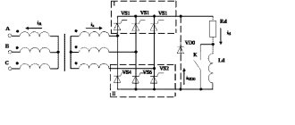
Short circuit in a circuit powered by constant voltage buses
Figure 1 shows a simple symmetrical three-phase circuit with active inductive reactance, which is typical for most real electrical networks. The circuit is powered from a source that, in normal operation and during a short circuit, maintains a symmetrical and unchanged three-phase voltage system at the terminals. The vector diagram of the circuit under consideration for normal operation is shown in Fig. 2, a. The angle φ between the current and voltage of each phase is determined by the ratio of the active and inductive reactances of the entire circuit, including the load.
Fig.1. Three-phase symmetrical circuit powered from constant voltage busbars (from an infinite power source)
Fig.2. Vector diagrams of currents and voltages: a - in normal mode; b - with a three-phase short circuit
A short circuit divides the circuit into two parts: the right with resistances r1 and x1 = ωL1 in each phase and the left, containing the power source and short-circuit resistances rK and xK = ωLK. Processes in both parts of the circuit during a three-phase short circuit proceed independently.
The right side of the circuit under consideration turns out to be shunted by a short circuit, and the current in it will be maintained only until the magnetic field energy stored in inductance L1 is converted into heat released in the active resistance r1. This current, with the active-inductive nature of the circuit resistance, does not exceed the normal mode current and, gradually attenuating to zero, does not pose a danger to the equipment.
A change in mode on the left side of the circuit containing the power source, in the presence of inductance LK, is also accompanied by a transient process. From the course “Theoretical Foundations of Electrical Engineering” we know the equation that describes this process:
(1)
where u and i are the instantaneous values of voltage and current of the phase under consideration, respectively.
Solving this equation gives an expression for the instantaneous value of the current at any time t from the beginning of the fault:
(2)
where Um is the amplitude value of the phase voltage of the source; ZK is the total resistance of the circuit section connected to the source (short-circuit circuit); α is the phase angle of the source voltage at the moment t = 0; φK is the shift angle of the current in the short-circuit circuit relative to the source voltage of the same phase; Ta is the time constant of the short-circuit circuit:
(3)
As can be seen from (2), the total short-circuit current consists of two components: forced, due to the action of the source voltage (the first term on the right side of the equation), and free, due to the change in the magnetic field energy reserve in the inductance LK (the second term of the equation).
The forced component of the short-circuit current is periodic in nature with a frequency equal to the frequency of the source voltage. This component is usually called the periodic component of the short-circuit current
(4)
where Iп,m is the amplitude value of the periodic component of the current.
The shift angle φK between the current and voltage vectors is determined by the ratio of the active and inductive resistances of the short-circuit circuit. For real circuits, usually xK » rK and φK = 45-90°. The vector diagram for the periodic component of the short circuit at φK = 90° is shown in Fig. 2b. Free current component
(5)
has an aperiodic nature of change, on the basis of which this current component is also called the aperiodic component of the short-circuit current.
The initial value of the aperiodic component of the short-circuit current in each phase is determined by expression (2) for time t=0:
(6)
here iK,0 is the initial value of the short-circuit current, which, taking into account the impossibility of changing the current abruptly in a circuit with inductance, is equal to i(0) - the current of the previous mode in a given phase at the moment t=0. The value of the periodic component of the current at t=0 is determined as
(7)
Of particular interest are the conditions for the occurrence of the maximum possible value of the total short-circuit current and its aperiodic component. From (6) and (7) with xK » rK and φK≈90° it follows that the maximum current value ia,0 will be if the voltage at the moment of the short circuit passes through the zero value (α=0) and the current in the circuit is up to There is no short circuit, i.e. i(0)=0. In this case, ia,0=Iп,m. The current change curve under the condition of the maximum value of the aperiodic current component is shown in Fig. 4. Here ia,0=Iп,m.
Fig.3. Change in short-circuit current in a circuit fed from constant voltage buses at the maximum value of the aperiodic component
The maximum instantaneous value of the total current usually occurs 0.01 s after the start of the short-circuit process (Fig. 3). It is called shock current and is designated iy. The shock current will be determined from (2) for the moment t=0.01s:
(8)
or
(9)
where ky is the shock coefficient depending on the time constant of the short-circuit circuit:
(10)
The transient process in the case of power supply from constant voltage buses ends after the aperiodic component of the current has attenuated, and then the total short-circuit current is equal to its periodic component, unchanged in amplitude.
The effective value of the current for an arbitrary short circuit time t is equal to:
periodic component
(11)
aperiodic component
(12)
full short circuit current
(13)
Add a link to a discussion of the article on the forum
RadioKot >Articles >
| Article tags: | Add a tag |
Three-phase circuits or what is the difference between phase and zero?
Author: Atomik Published 10/04/2006
Concepts PHASE
and
ZERO
follow from the topic
THREE-PHASE
(hereinafter -
3PH
)
CIRCUITS
, therefore we will consider them in detail.
What is this anyway? Here's what: If you connect several single-phase circuits (consisting of a generator, a load and two line wires: forward and reverse), the currents in which have the same frequency, but are shifted relative to each other in phase, then you can get a condition when the sum of the currents in return wires will be zero. Then we can combine all the return wires into one and dispense with them, thereby saving on wire material (you can buy more whiskey! ( To hell with whiskey - let's have sturgeon! Hereinafter, Kota's note.
)). This opportunity gave rise to the spread of multiphase circuits; in particular, in the production and transmission of electricity, almost exclusively 3P circuits are used. By the way, all the main links of 3F circuits (3F generator, 3F transformer and 3F motor) were developed by the Russian engineer Dolivo-Dobrovolsky back in the 1880s! The reason for the spread of 3F systems is also that the 3F generator, 3F transformer and 3F motor are the simplest in design, economical and reliable in operation compared to others.
A 3F system of electrical circuits is a set of three single-phase circuits in which an EMF of the same frequency acts, but is shifted by an angle of 120° from one another. A separate circuit of these three is called a PHASE. PHASE is a section through which the same current flows.
A 3F EMF system is symmetrical if these EMFs are shifted relative to each other by 120° and have equal amplitudes. 3F generators at power plants create precisely a symmetrical EMF system.
A 3F load is symmetrical if the complex resistances of all three of its phases are equal. If a symmetrical EMF system is applied to a symmetrical load, a 3F symmetrical system of currents will occur.
Some terminals of the phase windings of the generator are conventionally called the beginning and are designated ABC in the diagrams, while others are the ends and are designated XYZ.
The order in which the emf of the generator phases pass through the same values is called phase rotation.
The sum of the emf of a symmetrical system at any time is 0.
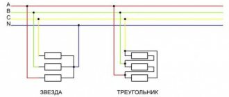
There are two ways to connect phases in 3P circuits: triangle and star. A star connection is a connection in which the XYZ ends of the generator phase windings are connected into a common unit called the generator NEUTRAL or ZERO point (N or O). The star connection is shown in Figure 1. Star phase connection of the generator:
The connection of the generator phases into a triangle is a connection in which the beginning of one PHASE was connected to the end of the next.
When there is no load (i.e., when the generator terminals are open), no current flows in the generator windings connected in a triangle because the sum of the symmetrical emfs gives “0”. Based on this, only four connections between the generator and the receiver are possible: 1. delta - delta 2. delta - star 3. star - delta 4. star - star
But this would be true if it were not for the neutral (zero) point that appears when connected by a star. After all, the middle points can also be connected. We get another method: 5. star - star, with neutral. (Y+Yn) That's what we need! This is the connection:
I wrote a lot here, I explain:
Complex (with a point) Ua, Ub, Uc - phase voltages. Complex Uab, Ubc, Uca - linear voltages. Complex Ia, Ib, Ic - Linear currents (shown from the generator to the receiver). Complex In - shown from the receiver to the generator; in fact, the neutral (the same ZERO in the socket) is the return wire.
And now the most interesting thing (at one time it amazed me) According to Kirchhoff’s second law:
Uab = Ua - Ub Ubc = Ub - Uc Uca = Uc - Ua
It follows from this that:
Uab + Ubc + Uca = 0!
(in symmetrical mode) According to Kirchhoff's first law:
Ia + Ib + Ic = In
In symmetrical mode In = 0
Therefore, in symmetrical mode a neutral is not needed!
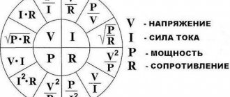
If you carefully examine the vector diagram presented in the figure, the question that worries many will become clear: why 220V, and not 200 or 250, etc. Or in general terms: “why does the scale of standard receiver voltages look like 127, 220, 380, 660.” Here's why. Let's look again at Figure 4, what do we see? Consider the voltage vector Uab. Uab = Ua*cos30° + Ub*cos30° = 2 Uph*cos30° = sqrt3*Uph Ul = sqrt3*Uph
Uph
, this is the potential difference between the line wire and the neutral.
Uл
, this is the Voltage between two linear wires (phase-to-phase).
Now let's take, for example, 220 volts as Uph, calculating Ul we get 381.05 Volts. Let's take these as Uph 381.05 and calculate again, we get 659.99 volts. And so on. That's where these mystical numbers come from - from phase shift angles and mathematics! So, with a symmetrical load, a neutral is not needed, since there will be no current in it anyway. Then the 3F system will be three-wire, which saves 50% on material compared to a single-phase system (with the same transmitted power). In practice, a 3P load occurs (3P motor), however, even in such a 3P circuit, an asymmetrical mode is still possible, which, for example, can be caused by a break in one of the phases, or an asymmetrical short circuit (between two phases). With an unbalanced load and no neutral, the potential of the neutral point of the load will not be zero. It can be determined using the two-node method by finding the neutral offset:
From the diagram without a neutral (Figure No. 1) it is clear that, in accordance with Kirchhoff’s second law, the phase voltages will not be equal to the EMF of the source by the amount of neutral displacement.
HP for asymmetrical mode without neutral:
In the absence of a neutral, the symmetry of the phase voltages is violated. For any change in one of the phases, point n will move along the plane, dragging the phase voltage vectors behind it. In short, it's rubbish. In this regard, they once told me: if you want to see fireworks, cut the neutral wire in the house opposite. As a result, when the load of only one of the phases changes, all three phase non-voltages change. The operation of the phases will not be independent; this is unacceptable, since consumers connected to different phases are designed to operate at a certain Uph.
To eliminate such dependence of one phase on another, i.e. The neutral wire is designed to ensure symmetry of phase voltages under unbalanced loads.
Despite the absence of potential difference on the neutral, current will flow through it due to load asymmetry. In short, the “excess current” flows down the neutral. Why is neutral called earth? Because at the power plant the zero point of the generator is grounded, i.e. literally the wire is buried in the ground. This is for insurance purposes. Well, if someone is interested in the question: “How does this all work in practice?”, then here is a simplified diagram for powering our apartments from a power plant.
From the 3F generator, the energy goes to the 3F transformer (the one we have at the substation) and from it it goes to our sockets on the wall (in the diagram, consumers are indicated by a resistor symbol and labeled as a 3F load)
And finally, let’s go over the main points of this topic. So, conclusions: a)
PHASE and ZERO are completely different things!
(Now we know that ZERO, in general, may not be needed, let’s connect all the return wires from the sockets, three at a time, to one point and that’s it, the main thing is that the load is symmetrical, but PHASE is definitely needed... So there are still differences b)
PHASE is actually a section through which the same current flows.
In the socket, on the wall, this is the wire through which the current comes to us from the generator. (in contrast to ZERO, through which it flows back to the generator, to its zero point) We can also say that this is one of the three alternating currents generated by the 3F generator. c)
ZERO (aka neutral) is actually a wire connecting the zero point of the generator and the zero point of the load.
d)
ZERO is literally grounded, but at the power plant.
e)
The advantage of the YN circuit is that it allows connection to 2 voltages: between two linear wires and between phase and neutral.
TAD (3F asynchronous motor U1 = 380/220) f)
When connecting the load phases in a triangle, each phase is under linear voltage, and when connected in a star, the voltage is several times less.
g)
For any connection scheme, in the case of a symmetrical mode, the calculation of a 3F circuit is reduced to the calculation of one of the phases.
h)
In practice, linear voltages and currents are indicated, since there is not always access for devices to the neutral point of the receiver.
These are all the main points about 3F circuits. Do you have anything to add? Write.
As usual, we put the questions here.
| What do you think of this article? | Did this device work for you? | |
| 38 | 0 | 0 |
| 1 | 1 |
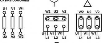
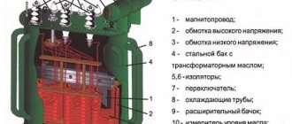
§60. Star connection diagram
Scheme "star with neutral wire".
When connecting the phase windings of a three-phase current source (for example, a generator) according to the “star with neutral wire” circuit, the ends of its three windings are connected to a common node 0, which is called the zero point, or source neutral (Fig. 206).
Rice. 206. Scheme “star with neutral wire”, direction of linear and phase currents and voltages in it
Receivers of electrical energy are combined into three groups ZA, ZB and Zc (load phases), the ends of which are also connected into a common node 0′ (zero point, or load neutral). The source windings are connected to the load phases with four wires. Wires 1, 2 and 3 connected to the beginnings of the phase windings (A, B, C) are called linear. Wire 4, connecting the zero points 0 and 0′, is called zero, or neutral.
The voltages uА, uв and uс between the beginnings and ends of the windings of individual source phases or load phases ZA, ZB and Zc are called phase. They are also equal to the voltage between each of the linear wires and the neutral wire. In the absence of voltage loss in the source windings (at no load), the phase voltages are equal to the corresponding e. d.s. in these windings.
Phase currents iA, iB, ic are the currents flowing through the source windings or load phases ZA, ZB and Zc. The voltages uAB, uBC, uCA between linear wires and the currents passing through these wires are called linear.
Let us conventionally assume the positive direction of the currents iA, iB and ic in the source phases - from the end of the corresponding phase to its beginning, in the load phases - from beginning to end, and in linear wires - from the source to the receiver.
We will consider the voltages uA, uB and uC in the source and load phases positive if they are directed from the beginning of the phases to the ends, and the linear voltages uAB, uBC, uCA - if they are directed from the previous phase to the next.
From Fig. 206 it follows that in the “star” circuit the linear currents are equal to the phase currents, i.e. Il = Iph, since there are no branches when transitioning from the source or load phase to the linear wire.
Instantaneous stress values according to Kirchhoff’s second law:
uАВ = uА – uB; uBC = uB – uС; uCA = uC – uA.
Moving from instantaneous voltage values to their vectors, we have:
Consequently, the linear voltage is equal to the difference between the vectors of the corresponding phase voltages.
Using the obtained vector equations, you can construct a vector diagram (Fig. 207, a), which can be converted into a diagram (Fig. 207, b). From this diagram it is clear that in a symmetrical three-phase system, the linear voltage vectors →uAB, →uBC, →uCA form an equilateral triangle ABC, inside which there is a symmetrical three-ray star of phase voltages →uA, →uB, →uC.
In isosceles triangles AOB, BOC and COA, the base is equal to Ul, the other sides are equal to Uf and the acute angle between these sides and the base is 30°.
Rice. 207. Vector voltage diagrams for the “star with neutral wire” circuit
Hence,
Ul = 2Uph cos 30° = 2Uph (√3)/2 = √3 Uph
Thus, in a three-phase system connected according to a “star with a neutral wire” circuit, the linear voltage is √3 times greater than the phase voltage. The value √З = 1.73 is the basis for the scale of nominal AC voltages: 127, 220, 380 and 660 V. In this series, each subsequent voltage value is 1.73 times greater than the previous one.
A current i0 passes through the neutral wire, the instantaneous value of which is equal to the algebraic sum of the instantaneous values of the currents passing in the individual phases: i0 = iA+iB+iC.
Passing from the instantaneous values of currents to their vectors, we have:
→i0=→iA+→iB+→iC.
Current vectors →iA, →iB and →iC are shifted relative to the corresponding voltage vectors →uA, →uB, →uC by angles →iA, →iB, →iC (Fig. 208, a). The values of these angles depend on the relationship between active and reactance included in a given phase.
The same diagram shows the addition of vectors →iA, →iB and →iC to determine the current vector →i0. Usually the current →i0 is less than the currents
Rice. 208. Vector diagrams of voltages and currents in individual phases for the “star with neutral wire” circuit with uneven (a) and uniform (b) phase loads
IA, 1B and IC are in the line wires, so the neutral wire has a cross-sectional area equal to or even slightly less than the cross-sectional area of the line wires.
In the “star with neutral wire” circuit, electrical energy receivers can be connected to two voltages: linear Ul (when connected to two linear wires) and phase UФ (when connected to the neutral and one of the linear wires).
Star circuit without neutral wire.
With a uniform or symmetrical load of all three phases, when the same active and reactive resistances are included in all phases (RA = RB = RC and XA = XB = XC), the phase currents iA, iB and iC will be equal in magnitude and shifted from the corresponding phase voltages at equal angles. In this case, we obtain a symmetrical system of currents, in which the currents iA, iB, iC will be phase shifted relative to each other by an angle of 120°, and the current i0 in the neutral wire at any time is zero (Fig. 208, b).
Obviously, with a uniform load, you can remove the neutral wire and transmit the electrical energy of the source to the receiver through three linear wires 1, 2 and 3 (Fig. 209).
Rice. 209. Scheme “star without neutral wire”
This circuit is called a “star without a neutral wire.” With a three-wire system for transmitting electrical energy, at every instant the current flows through one (or two) wires from the three-phase current source to the receiver, and through the other two (or one) it flows back from the receiver to the source (Fig. 210).
Fig. 210. Curves of changes in currents in linear wires (a) with a three-wire system and the direction of currents in them at different times (b c, d)
The vector voltage diagram for the “star without neutral wire” circuit with a uniform phase load will be the same as for the “star with neutral wire” circuit (see Fig. 207).
The relationships between phase and linear currents and voltages will be the same:
Il = IФ and Ul = √3 UФ
It should be noted that the “star without neutral wire” circuit can only be used with a uniform phase load. In practice, this only occurs when connecting electric motors to three-phase current sources, since each three-phase electric motor is equipped with three identical windings that evenly load all three phases.
With an uneven load, the voltages in individual load phases will be different. On some phases (with lower resistance) the voltage will decrease, and on others it will increase compared to normal, which is unacceptable.
An almost uneven phase load occurs when electric lamps are supplied with three-phase current, since in this case the distribution of current between all three phases cannot be guaranteed (individual lamps can be turned on and off individually). Particularly dangerous in a “star without a neutral wire” circuit is a break or short circuit in one of the phases.
It can be shown by constructing the corresponding vector diagrams that if there is a break in one of the phases, the voltage in the other two phases decreases to half the linear one, as a result of which the lamps included in these phases will burn with insufficient power.
If there is a short circuit in one of the phases, the voltage in the other phases increases to linear, i.e. √3 times, and all the lamps turned on in these phases will burn out. Therefore, in the “star with neutral wire” circuit, in order to avoid breaking the neutral wire circuit, fuses and switches are not installed in it.