A Peltier element is usually called a converter that is capable of operating from a temperature difference. This happens by flowing electric current through conductors through contacts. For this purpose, special plates are provided in the elements. Heat passes from one side to the other.
Today, this technology is in demand primarily due to its significant heat transfer power. Additionally, the devices can boast of compactness. The radiators installed on many models are weak. This is due to the fact that the heat flow cools quite quickly. As a result, the desired temperature is constantly maintained.
This element has no moving parts. The devices operate absolutely silently, and this is a definite advantage. It should also be said that they can be used for a very long time, and breakdowns occur extremely rarely. The simplest type consists of copper conductors with contacts and connecting wires. Additionally, there is an insulator on the cooling side. It is usually made from ceramics or stainless steel.
Why are Peltier elements needed?
Peltier elements are most often used to make refrigerators. Usually we are talking about compact models that can be used, for example, by motorists on the road. However, this is not the end of the range of applications of the devices. Recently, Peltier elements have been actively installed in sound and acoustic equipment. There they are able to perform the functions of a cooler.
As a result, the device amplifier is cooled without any noise. For portable compressors, Peltier elements are indispensable. If we talk about the scientific industry, scientists use these devices to cool the laser. In this case, it is possible to achieve significant stabilization of the study wave of LEDs.
Technological part
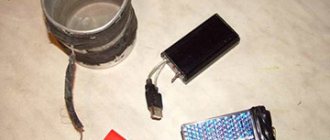
We had a radiator, an aluminum plate, a Peltier element, a handful of radio components, a piece of foil PCB and a variety of screws and nuts.
I don’t remember further. So, all the components are assembled, you can start assembling.
I apologize for the plate that was marked and drilled in two places - it only occurred to me later that it would be nice to photograph the entire assembly process from the very beginning.
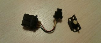
The first trouble that awaited me was the 12-volt standard fan on the radiator. Since I am going to produce only 5 volts, and even at a fairly small maximum current, this could create a problem.
First, I cast my bait in all the radio and computer stores in Perm, but nowhere was there a 5-volt 80x80 millimeter fan. And if there were, they were smaller in size and with a current of more than 200 mA, which was too much.
Then I did some digging on eBay and found that the fan I needed cost from 300 rubles. But it was pointless to hope for quick delivery, and so I left this option as a backup.
And only after all the searching I guessed to connect the standard 12-volt fan to a 5-volt voltage source. It turned out that it blows quite well, and at the same time does not consume very much current. Therefore, I decided to leave it for now, and after testing, if necessary, order a fan on eBay.
I marked an aluminum plate and drilled two holes in it for mounting the radiator and two for the voltage converter board. I made the holes with a diameter of 4 millimeters (for the screws from the designer), and on the outside I widened them to 7.5 millimeters to hide the screw heads. After that, I rounded the sharp corners with a file and walked with coarse sandpaper over all surfaces of the plate, and fine sandpaper where the Peltier element was pressed.
At this point, I considered the processing of the substrate complete and began manufacturing the voltage converter. The pulse boost voltage converter is assembled on the L6920 IC, which starts operating at an input voltage of 0.8 volts and allows you to remove a fixed voltage of 3.3 or 5 volts, or variable from 1.8 to 5.5 volts, from its output.
The schematic diagram of the converter is typical and taken from the datasheet.
To obtain 5 volts at the output of the circuit, leg 1 is connected to the common wire. It is also configured to output a low level on pin 3 when the input voltage drops below 1.5 volts.
For the circuit, a printed circuit board was laid out, on which fastening to the base-substrate was provided using the same parts from the children's designer set. I am not worried about the board overheating, since it has forced cooling by an air flow blown from the radiator.
I had to tinker with the macro of the case that contained the microcircuit I bought. On the store's website it was stated that it was in the SSOP-8 case. As it turns out, there is no such case in the standard set of Sprint Layout macros. I found a drawing of the SSOP-8 case and made a macro, after which I routed the board. After a test print, it turned out that the microcircuit is somewhat wider and does not fit on its contact pads. Googling a specific chip model (L6920D) led me to the Chip-Dip website, where I learned that the IC with index D is manufactured in a TSSOP-8 package. Scratching my head, I found a drawing of this case, created a macro and re-routed the board. Now everything turned out to be correct.
The board was made using LUT and assembled. It turned out that soldering the TSSOP-8 case without a hair dryer is very inconvenient. But we are seasoned people, we soldered FTDI microcircuits with a pin pitch of 0.4 millimeters.
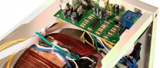
Now you can start installing the Peltier element and radiator. I coated the substrate and the radiator at the points of contact with the element with thermal paste. Then he tightened the resulting “sandwich” with nuts.
It turned out that the converter board does not fit, the input connector rests on the radiator, I miscalculated slightly. I turned the mounting brackets over, hung the board outside, and added two more brackets to protect the elements from mechanical damage. Here's what we ended up with:
Now you can check the functionality of the generator. I heated it on a gas burner. I decided not to install a fan for now.
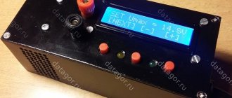
To begin with, it turned out that I mixed up the polarity of connecting the element to the converter. Although everything seemed to be correct - the black wire is to minus, the red wire is to positive. However, the generator did not want to work. Then I changed the polarity of the element connection.
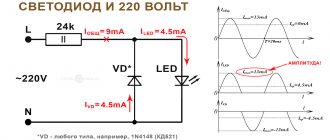
The generator started working - first both LEDs lit up, signaling the presence of 5 volts at the output and low voltage at the input, then the red LED went out - the voltage rose above one and a half volts.
To my displeasure, it turned out that without a fan, after a couple of minutes of operating the system, the radiator became noticeably hot. It won't work that way.
The next day, I walked around the metal market and several computer flea markets, but when I asked about 5-volt fans, they shrugged their shoulders everywhere and advised me to go “to that place over there” that I had already been to a couple of minutes ago. As a result, I went home empty-handed.
At home, I conducted an experiment on powering a standard 12-volt fan from the 5-volt output of the converter. The results did not please me - the converter, with obvious reluctance, turned off the red LED, and the fan twitched weakly for several seconds, trying to start. The air flow from the fan running at half power was not enough for normal cooling - the radiator heated up just as quickly, although it no longer burned my fingers. In the end, I decided to order the fan from Ebay.
Disadvantages of Peltier models
It would seem that such a simple and effective device has no drawbacks, but there are some. First of all, experts immediately noted the low penetration capacity of the module. This suggests that a person will have certain problems if he wants to cool a device that operates from a network with a voltage of 400 V. In this case, a special dielectric paste will partially help solve this problem. However, the current breakdown will still be high and the winding of the Peltier element may not withstand it.
Additionally, these models are not recommended for use in precision electronics. Since the design of the element contains metal plates, the sensitivity of the transistors may be impaired. The last disadvantage of the Peltier element is the low efficiency. These devices are not capable of achieving a significant temperature difference.
Design part
To begin with, I ordered the same Peltier element from the Chinese on e-Bay (enough for experiments).
It cost me 320 rubles. What pleased me was the expedited, tracking, but free delivery. Plus, the goods were sent literally an hour after payment (and it was on Sunday). While the Peltier element was traveling, I thought through the design of the future thermoelectric generator, found a suitable radiator with a fan (an ancient processor radiator worked perfectly), and also dug up on the Internet a circuit for a DC-DC converter with a maximum output current of 1 ampere at a voltage of 5 volts.
I did not consider it advisable to make a wood chip stove following the example from that article. The metal from which computer hardware is made is very soft; it will “sink” when exposed to high temperatures, and it will burn out quickly. Therefore, it was decided to make a “removable version” of the generator, which could be mounted on the side of a stationary stove or leaned against a pot standing on a fire. And in order to avoid frying the Peltier element over an open fire under such conditions, a heat-resistant but heat-conducting gasket was needed. To do this, I managed to get a piece of thick aluminum plate measuring 100x120x5 millimeters.
To press the Peltier element to the aluminum substrate, and, in turn, press the radiator to it, I decided to use a children's metal construction set that I once bought for robotics needs.
But the Peltier element arrived, and it was time for assembly.
Module for regulator
Making a Peltier element for a regulator with your own hands is quite simple. To do this, you should prepare two metal plates in advance, as well as wiring with contacts. First of all, conductors are prepared for installation, which will be located at the base. They are usually purchased with the “PP” marking.
Additionally, for normal temperature control, semiconductors should be provided at the output. They are necessary in order to quickly transfer heat to the top plate. To install all elements, you should use a soldering iron. To complete the Peltier element with your own hands, last of all, connect two wires. The first is mounted at the lower base and fixed at the outermost conductor. Contact with the plate should be avoided.
Next, attach the second wire at the top part. Fixation is also carried out to the outermost element. In order to check the functionality of the device, a tester is used. To do this, two wires need to be connected to the device. As a result, the voltage deviation should be approximately 23 V. In this situation, much depends on the power of the regulator.
Research part
Actually, why the Peltier element?
It is much more logical to purchase a flashlight with a muscle drive (“ground beetle”), solar panels, or, at worst, build a windmill. Previously, I also thought that it was quite possible to get by with ground beetles. But it has a lot of moving parts, which are made by Uncle Liao from cheap plastic. The first breakdown in the conditions of the Great Arctic Fox - and you are left without electricity. Well, you ask, why not solar panels? There are no moving parts. I agree, I will answer, but in conditions of a nuclear or volcanic winter or under a two-meter concrete roof of a shelter, it is not so easy to catch the sun.
Windmill? What area should its blades be so that it can spin even in a weak wind? Moving parts, again. The windmill is suitable for permanent installation when equipping a long-term shelter.
Having considered these arguments, I became despondent. But soon I accidentally came across the website nepropadu.ru (no advertising, only a link to the source material). I sat on it continuously for two days, and in the process I came across a very interesting article about a wood chip stove made from a case from a computer power supply with a Peltier element on the side (link at the end of the post). There were a lot of skeptics in the comments, but the author wrote that he calmly charged the phone from a connected Chinese DC-DC converter... I was hooked.
Refrigerators with thermistor
How to make a Peltier element with your own hands for a refrigerator with a thermistor? Answering this question, it is important to note that the plates for it are selected exclusively from ceramics. In this case, about 20 conductors are used. This is necessary so that the temperature difference is higher. The efficiency can be increased by up to 70%. In this case, it is important to calculate the power consumption of the device.
This can be done based on the power of the equipment. A refrigerator using liquid freon is ideal in this case. The Peltier element itself is installed near the evaporator, which is located next to the motor. To install it, you will need a standard set of tools, as well as gaskets. They are necessary in order to protect the model from the starting relay. Thus, the cooling of the lower part of the device will occur much faster.
To achieve a temperature difference (Peltier effect) with your own hands, you may need at least 16 conductors. The main thing is to reliably insulate the wires that will be connected to the compressor. In order to do everything correctly, you must first disconnect the refrigerator dryer. Only after this is it possible to connect all contacts. Once installation is complete, the voltage limit should be checked using a tester. If the element malfunctions, the thermostat is the first to suffer. In some cases, a short circuit occurs.
Brief history of the discovery and justification of the physics of work
The operation of a Peltier element is based on the physical principle of current passing through two contacting plates made of materials with different levels of passing current energy, or in other words - semiconductors of different types. At the point of their connection, heating will be observed when current is supplied in one direction, and a decrease in temperature when it moves in the opposite direction.
The effect was discovered back in the 18th century by Jean-Charles Peltier, who obtained it by accident by connecting bismuth and antimony contacts from a current source. A drop of water located at the point of contact turned into ice, which aroused the interest of the researcher. The discovery did not receive practical application due to the low prevalence of electrical engineering in the specified period of time. We remembered it only later, in the age of the development of microelectronics, the components of which needed miniature cooling, preferably without liquids and moving parts (pumps, fans and others).
Selling Peltier element assemblies:
The Peltier element can be created not only from semiconductors. But, unfortunately, the effect of using various conductive metals will be lower and will be almost completely lost due to their heating at the point of contact and the general thermal conductivity of the material.
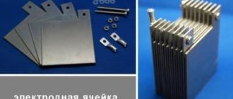
Internal structure of the Peltier element:
In general, the design looks like a set of cubic-shaped electrodes made of n- and p-type semiconductors. Each of them is connected to opposite conductive contacts, and all of these pairs are connected to each other in series. Moreover, the arrangement of the elements is carried out so that the connecting metals between assemblies of semiconductors of the same type are in contact with the first side of the device in general, and the second with the opposite. The p- and n-cubes themselves are often made of bismuth telluride and a silicon-germanium alloy. Connecting contacts are usually made of copper, aluminum or iron. The main requirement here is good thermal conductivity. The number of pairs in one design is not limited, and the more there are, the more efficiently the Peltier element works. When voltage is applied to the assembly, one side heats up and the other cools.
Schematic diagram of connections in a Peltier element:
The year of discovery of the opposite effect, expressed in the generation of current during cooling and heating of connected conductors from different metals, is considered to be 1821. The discovery was made by T. I. Seebeck, who the very next year published it in an article intended for the Prussian Academy of Sciences, with the title “On the issue of magnetic polarization of some metals and ores that occurs under conditions of temperature difference.”
Although, according to his work, the generation system operates not only when using semiconductors, with them its efficiency is much higher.
Peltier element intended for current generation purposes:
Model for refrigerator 15 V
You can make a Peltier refrigerator with your own hands with low throughput. The modules are mainly mounted near radiators. In order to securely fasten them, experts use corners. The element should not lean against the filter, and this should be taken into account.
To complete a Peltier thermoelectric module with your own hands, the bottom plate is mainly chosen from stainless steel. Conductors, as a rule, are used with the marking “PR20”. They can withstand a maximum load of 3 A. The maximum temperature deviation can reach 10 degrees. In this case, the efficiency can be 75%.
Materials for creating thermocouples
Obviously, ordinary metals are not suitable for creating powerful systems. Pairs with a power of 100 μV per 1 degree are required. In the latter case, high efficiency is achieved. The materials are alloys of bismuth, antimony, tellurium, silicon, and selenium. The disadvantages of the components include fragility and relatively low operating temperatures. Low efficiency adds limitations, but with the introduction of nanotechnology there is hope that the usual limits will be overcome. Among the promising areas, scientists name the development of a fundamentally new semiconductor base with truly unique properties, including the exact value of the energy levels of materials.
Peltier elements in 24 V refrigerators
Using a Peltier element, you can make a refrigerator with your own hands only from conductors with good sealing. At the same time, they must be stacked in three rows for cooling. The operating current in the system must be maintained at 4 A. You can check it using a conventional tester.
If you use ceramic plates for the element, the maximum temperature deviation can be achieved at 15 degrees. The wires to the capacitor are installed only after the gasket has been placed. You can attach it to the wall of the device in different ways. The main thing in this situation is not to use glue, which is sensitive to temperatures above 30 degrees.
Where is it used?
The miniaturization of these elements and their relatively low energy consumption - coupled with the absence of moving parts or various liquids used for heat transfer - provides a wide range of niches of use. This includes car air conditioners, cooling systems for microcircuits and electronic elements, mini-refrigerators, stands that maintain a certain temperature of containers placed on top. In addition to the above, equipment based on Peltier elements is used in specific areas, such as PCR amplifiers, heated camera flash systems, telescopes (to reduce thermal noise) and radiation receivers of infrared devices.
Less often you can see the real element as part of the design of generators. Although devices of a similar class periodically appear on the markets, for example, in the form of flashlights powered by the heat of the human body or weak machines that produce electric current to recharge the batteries of smartphones or laptops.
Voltage obtained at the output of Peltier elements:
Peltier element for car cooler
To make a high-quality auto-refrigerator with your own hands, a Peltier module (module) is selected with a plate whose thickness is no more than 1.1 mm. It is best to use non-modular wires. Copper conductors will also be required for operation. Their capacity must be at least 4A.
Thus, the maximum temperature deviation will reach 10 degrees, this is considered normal. Conductors are most often used with the marking “PR20”. They have recently shown themselves to be more stable. They are also suitable for various contacts. A soldering iron is used to connect the device to the capacitor. High-quality installation is only possible on the relay block gasket. The differences in this case will be minimal.
Conclusions on the design of a homemade refrigerator
Readers will draw the rest of their conclusions on their own: a homemade refrigerator will give 2 degrees of heat on the Celsius scale if you equip the device with three Peltier elements with coolers. It is permissible to generalize experience, select optimal insulation, and vary conditions. For example, remove coolers so as not to make noise and waste energy. This will simplify the design. But we want to cool the ardor of the inventors: in real, not homemade refrigerators, two fans are used, for the cold and hot circuits. Experiment.
The refrigerator device will withstand the computer power supply. Remember how much the processor consumes! The Peltier element is far from the most important thing inside. The voltage has already been adjusted in advance, so you don’t have to look for rare parts. You buy three Peltier elements to make your own refrigerator, take a power supply from an old PC, build a box with two coolers, and get the finished product. Moreover, it can operate from a car battery.
The principle of operation of the refrigerator is so obvious that children can understand it. When the direction of the current changes, the Peltier elements work to heat. It's good to have warm food nearby when there is no heating device around. In the latter case, the law works in the opposite direction. Three Peltier elements inside a homemade refrigerator will provide a temperature 18 ºС above the environment. If the car has 25, the box will show 43. Enough to have a snack and not complain. It turns out that there are two devices in one person.
We would like to thank the author of the YouTube video for the great idea on how to make a refrigerator yourself. Let the idea not be very successful, but only because the volume is large. Peltier processor elements are not so powerful that they can single-handedly overcome a large volume that is not fully formed.
How to make an element for a drinking water cooler?
A DIY Peltier module (element) for a cooler is quite simple. It is important to select only ceramic plates for it. At least 12 conductors are used in the device. Thus, the resistance will be maintained high. The connection of elements is usually carried out using soldering. There must be two wires for connecting to the device. The element must be attached to the bottom of the cooler. In this case, it may come into contact with the cover of the device. In order to eliminate cases of short circuits, it is important to fix all wiring on the grid or housing.
Heat release
The cooling effect of a TEM is small, but it produces a lot of heat. When it is used in a system unit, the temperature inside increases significantly, affecting the operation of other equipment. Additional means to reduce it are fans and radiators that create thermal exhaust.
The thermal regime of the module must be correctly calculated so that there is no overheating and condensation does not form on the electronic boards
The Peltier cooler is selected with optimal power, where it is important to ensure the correct ratio of the temperature inside the case, the cooling object and air humidity
Air conditioners
The Peltier module (element) is made with your own hands for an air conditioner only with conductors of the PR12 class. They are chosen for this task mainly because they cope well with low temperatures. At most, the model is capable of producing a voltage of 23 V. The resistance indicator will be at the level of 3 ohms. The temperature difference reaches a maximum of 10 degrees, and the efficiency is 65%. Conductors can only be laid in one row between sheets.
Pros and cons of a wood-fired power plant
A wood-fired power plant is:
- Fuel availability;
- Possibility to get electricity anywhere;
- The parameters of the generated electricity are very different;
- You can make the device yourself.
- Among the shortcomings it is noted:
- Not always high efficiency;
- Cumbersome design;
- In some cases, generating electricity is just a side effect;
- To generate electricity for industrial use, large amounts of fuel must be burned.
In general, the production and use of solid fuel power plants is an option worthy of attention, and it can not only become an alternative to power grids, but also help in places remote from civilization.
Manufacturing of generators
You can make a generator using a Peltier module (element) with your own hands. Device performance will increase by a total of 10%. This is achieved due to greater cooling of the motor. The device can withstand a maximum load of 30 A. Due to the large number of conductors, the resistance can be 4 ohms. The temperature deviation in the system is approximately 13 degrees. The module is attached directly to the rotor. To do this, you must first disconnect the central shaft. In many cases the stator does not interfere. To prevent the rotor winding from heating up from the inductor, ceramic plates are used.
Classic version
As noted, a wood-fired power plant uses several technologies to produce electricity. The classic one among them is steam power, or simply the steam engine.
Everything is simple here - wood or any other fuel, when burned, heats up the water, as a result of which it turns into a gaseous state - steam.
The resulting steam is supplied to the turbine of the generating set, and due to rotation, the generator generates electricity.
Since the steam engine and generator set are connected in a single closed circuit, after passing through the turbine the steam is cooled, fed back into the boiler, and the whole process is repeated.
This power plant scheme is one of the simplest, but it has a number of significant disadvantages, one of which is the danger of explosion.
After water passes into a gaseous state, the pressure in the circuit increases significantly, and if it is not regulated, there is a high probability of rupture of the pipelines.
And although modern systems use a whole set of valves that regulate pressure, the operation of a steam engine still requires constant monitoring.
In addition, ordinary water used in this engine can cause scale to form on the walls of the pipes, which reduces the efficiency of the station (scale impairs heat transfer and reduces the throughput of the pipes).
But now this problem is solved by using distilled water, liquids, purified impurities that precipitate, or special gases.
But on the other hand, this power plant can perform another function - to heat the room.
Everything is simple here - after performing its function (rotation of the turbine), the steam must be cooled so that it turns into a liquid state again, which requires a cooling system or, simply, a radiator.
And if you place this radiator indoors, then in the end we will receive not only electricity from such a station, but also heat.
Cooling a video card on a computer
To cool the video card, you should prepare at least 14 conductors. It is best to select copper models. Their heat conductivity coefficient is quite high. To connect the device to the board, non-modular type wires are used. The model is mounted near the video card cooler. Small metal corners are usually used to secure it.
To fix them, you can use regular nuts. The appearance of excessive noise during operation indicates that the device is not working properly. In this case, it is necessary to check the integrity of the wiring. You also need to inspect the conductors.
Gas generators
The second type is gas generators. Such a device can be used in several directions, including generating electricity.
It is worth noting here that such a generator itself has nothing to do with electricity, since its main task is to produce flammable gas.
The essence of the operation of such a device is that during the oxidation of solid fuel (its combustion), gases are released, including flammable ones - hydrogen, methane, CO, which can be used for a variety of purposes.
For example, such generators were previously used in cars, where conventional internal combustion engines worked perfectly on the emitted gas.
Due to the constant rise in fuel prices, some motorists and motorcyclists have already begun installing these devices on their cars.
That is, to get a power plant, it is enough to have a gas generator, an internal combustion engine and a regular generator.
The first element will release gas, which will become fuel for the engine, which in turn will rotate the generator rotor to produce electricity as output.
The advantages of power plants using gas generators include:
- Reliability of the design of the gas generator itself;
- The resulting gas can be used to operate an internal combustion engine (which will drive an electric generator), a gas boiler, a furnace;
- Depending on the internal combustion engine and electric generator involved, electricity can be obtained even for industrial purposes.
The main disadvantage of the gas generator is the bulkiness of the design, since it must include a boiler where all the processes for producing gas take place, a system for its cooling and purification.
And if this device is used to generate electricity, then the station must also include an internal combustion engine and an electric generator.
Peltier element for air conditioner
To make a high-quality Peltier element with your own hands for an air conditioner, double plates are used. Their minimum thickness should be at least 1 mm. In this case, you can hope for a temperature deviation of 15 degrees. After equipping the modules, the performance of air conditioners increases on average by 20%. Much in this situation depends on the ambient temperature. The stability of the mains voltage should also be taken into account. With minor interference, the device can withstand a load of approximately 4 A.
When soldering conductors, they should not be placed too close to each other. To properly complete Peltier modules with your own hands, the input and output contacts must be installed only on one of the two plates. In this case, the device will be more compact. A serious mistake in this situation would be to connect the module directly to the unit. This will lead to inevitable damage to the element.
DIY Peltier dehumidifier
Unlike the same air conditioner, the implementation of this idea is completely justified. The DIY Peltier dryer has a simple design and low cost, and its cooling module lowers the temperature of the radiator below the dew point, which leads to the deposition of moisture contained in the air passing through the device. Next, the settled water is sent to a special storage tank (Figure 6).
Despite the low efficiency, the efficiency of such a device can be called quite satisfactory.
Do-it-yourself Peltier dehumidifier:
- It connects without problems - a constant voltage is supplied to the output wires, the value of which is written in its datasheet.
- It has a standard polarity - the red wire goes to plus, the black wire to minus; if they are mixed up, the cooled and heated surfaces will change places.
- It is checked tactilely - when connected to a voltage source, one side will be cold, the other will be warm.
- If there is no current source nearby, we connect the probes to the terminals of the module and bring a lit match or lighter to one of the sides and observe the readings of the device.
Figure 6. Air dryer assembly diagram
Installing the module on a capacitor
To install a Peltier module with your own hands, it is important to evaluate the power of the capacitor. If it does not exceed 20 V, then the element should be mounted with conductors marked “PR30” or “PR26”. In order to fix the Peltier module (element) on the capacitor with your own hands, use small metal corners.
It is best to install them four on each side. In terms of performance, the capacitor can ultimately add plus 10%. If we talk about heat losses, they will be insignificant. The efficiency of the device is on average 80%. The modules are not designed for high-voltage capacitors. In this case, even a large number of conductors will not help.
Explanation of markings
All thermal modules have a special marking containing several letters and numbers. This designation is easy to decipher:
- the first two letters are always the same - TE, they indicate that this is a thermocouple;
- the next letter indicates the size: C – standard and S – small;
- the number before the hyphen shows how many layers there are in this module;
- the first three digits after the hyphen indicate the number of thermocouples;
- the last two digits provide information about the rated current in Amperes.
Let's look at decoding using a specific example. The photo shows a standard size thermoelement with one cascade (layer). The device has 127 thermocouples. And the rated current is 6 Amperes.