TIA/EIA-568-B
is a set of three telecommunications standards released by the Telecommunications Industry Association in 2001, which replaced the outdated TIA/EIA-568-A standard. These standards describe the construction of telecommunications structured cabling systems in buildings.
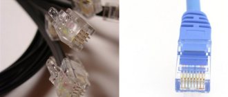
These standards are best known for two tables T568A and T568B, which describe the connection of twisted pair cable conductors to the pins of 8P8C connectors (often erroneously called RJ-45) when organizing an Ethernet network.
Tables T568 [edit | edit code ]
Straight through cable [edit | edit code ]
When connecting Ethernet terminal equipment (such as a computer, network printer) to switching equipment (hub/switch/router), both ends of the cable are crimped equally (so-called straight cable). In clause 6.2.1 of the standard, for horizontal connections, table T568A is given first, and also, as an option, if necessary, it is allowed to use table T568B. For the USA, federal law (NCS, FTR 1090-1997) allows switching only according to table T568A. In practice, during the construction of SCS and the production of patch cords, table T568B is more often used (including some American manufacturers, in particular AMP).
EIA/TIA-568A option:
Pin No. - core color - Pin No. on the other end of the cable
| 1 | = = = = | = = = = | 1 green-white |
| 2 | ==== | ==== | 2 green |
| 3 | = = = = | = = = = | 3 orange-white |
| 4 | ==== | ==== | 4 blue |
| 5 | = = = = | = = = = | 5 blue-white |
| 6 | ==== | ==== | 6 orange |
| 7 | = = = = | = = = = | 7 brown-white |
| 8 | ==== | ==== | 8 brown |
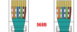
and according to the EIA/TIA-568B standard:
Pin No. - core color - Pin No. on the other end of the cable
| 1 | = = = = | = = = = | 1 orange-white |
| 2 | ==== | ==== | 2 orange |
| 3 | = = = = | = = = = | 3 green-white |
| 4 | ==== | ==== | 4 blue |
| 5 | = = = = | = = = = | 5 blue-white |
| 6 | ==== | ==== | 6 green |
| 7 | = = = = | = = = = | 7 brown-white |
| 8 | ==== | ==== | 8 brown |
Crossover cable [edit | edit code ]
The use of a straight cable is designed so that one (and only one) of the ends of the cable is connected to the switch port, and the crossing of the Rx (receive) and Tx (transmit) signal lines is performed inside the port. When directly connecting two pieces of network equipment (for example, two computers or two hubs), it is necessary to use a special, so-called. cross, cable (English crossover). For such a cable, the crossing of the Rx and Tx lines is performed by crimping one of the ends of the cable.
Since the tables T568A and T568B differ from each other precisely in that pairs 1-2 and 3-6 are swapped in them, to make a crossover cable for a 10BASE-T and 100BASE-T network, it is enough to crimp one end of the cable according to one table, and the other end is on the other.
It should be remembered that devices that support the 1000BASE-T standard transmit data over all four pairs of the cable, with each pair transmitting a signal in both directions at once, and the frames are marked in a special way, which prevents them from being assembled incorrectly by the receiving device. Therefore, any end of a cable designed to work with any 1000BASE-T devices, be it switches or nodes, can be crimped according to any given scheme.
We crimp the twisted pair and socket
Straight wire crimping according to T568B standard
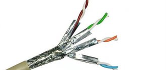
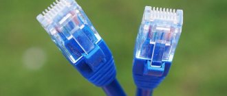
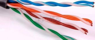
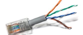
When installing local networks today, the most common unshielded twisted pair cable is category 5 (CAT-5E) - Fig. 4.1.
Rice.
4.1. This is what a twisted pair cable looks like
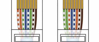
The crimping of such a cable for connecting a PC to a HUB according to the T568B standard is shown in Fig. 4.2.
Rice.
4.2. Direct crimp for PC-HUB connection (Same color of conductors on both sides of the cable)
Note
Crimping (crimping) according to version T568A is a standard used in the USA and Canada, and in Russia, the T568B standard is mainly used.
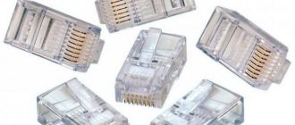
To crimp (crimp) a twisted pair, you will need a pair of RJ-45 connectors and special pliers (crimper) - Fig. 2.3-2.5.
Rice.
4.3. RJ-45 connector pin numbering
Rice.
4.4. Crimper
Fig.
4.5. The connector is inserted into the crimper
Sequence of actions when crimping:
- Carefully cut the end of the cable using the cutter built into the crimping tool.
- Remove the insulation from the cable using the knife built into the crimping tool.
- Separate and unravel the wires, align them in one row. Nip the wires so that a little more than a centimeter remains (see note).
- Insert the wires into the RJ-45 connector. Make sure all wires are fully inserted into the connector and rest against its front wall.
- Insert the connector into the connector crimper.
- Press the pliers so that the connector contacts clamp the conductors inside it.
Note
In Fig.
Figure 4.6 shows incorrect crimping of a twisted pair cable. In the example on the left, the strands are left too long, which leaves the distance from the connector to the braid unprotected. The cable also loses strength. In the second example, the cores are cut too short, the braiding fits into the connector and the length of the ends of the conductors does not allow them to create full contact with the connector. Rice.
4.6. Cable crimping errors
Result control
To check the correctness of the crimp, connect the network card and the HUB (switch, switch) with a cable and make sure that the cable is working correctly.
Another option is to use a special tester with LED indication (Fig. 4.7). Rice.
4.7. Appearance of the tester for testing twisted pairs RJ-45 model FA-7012B
There are many testers on sale for testing RJ-45 twisted pairs of varying levels of complexity and price range. However, their operating principle is similar. For example, the FA-7012B cable tester consists of 2 functional blocks - a transmitter and a receiver, which are connected to the ends of the cable line via RJ-45 or RJ-12 connectors. It detects broken pairs, shorted pairs, reversed wires within a pair, reversed pairs, and reversed wires between different pairs. The device also allows you to check the integrity of the cable shield. The transmitter unit sequentially queries the status of each wire in the cable, and the receiver unit returns a response for the pair that is not in use at a particular moment. Consecutive lighting of the LEDs indicates correct connection. The device is powered by 1 9 V Krona battery.
Crimp a Category 5 socket to an RJ45 connector
A standard diagram for connecting a PC to a local or global network is shown in Fig. 4.8.
Rice.
4.8. Typical scheme for connecting a home or office PC to a network
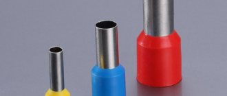
Just like the cable itself, twisted pair, network sockets differ by category. Ideally, for a professional installation you will need: a Category 5e RJ-45 wall mount receptacle, a twisted pair stripper and trimmer, a twisted pair termination tool, 4-pair Category 5e UTP cable, and cable markers (Fig. 4.9).
Rice.
4.9. Socket installation kit (on the left is a tool for stripping insulation, on the top is for cutting the ends of conductors)
All contacts in Category 5 sockets are numbered, so there should be no problems with cable routing.
Situation 1. Socket with one socket for 8 wires (video)
To work, you will need a screwdriver with a flat thin tip, the thickness not exceeding the diameter of the copper conductor of the twisted pair - fig. 4.10. You can also push the wires into the slots of the socket with a knife with a thin blade, for example, a stationery knife, in which the blade extends.
Rice.
4.10. Numbering of contacts in a socket with one socket according to the T568B standard (for the T568A standard, the colors of the socket contacts are also indicated)
The cable is prepared for cutting; its outer sheath is removed to a length of no more than 3 cm. Pairs are unraveled to a length of no more than 13-15 mm. Next, according to the color scheme, the conductors are inserted into the comb one by one, tucked in with the side plane of the screwdriver blade, and then pushed in with the end of the blade until it stops. In special cases (if necessary), two twisted pair cables mounted on one plug can be inserted into one socket (Fig. 4.11).
Rice.
4.11. Special cable crimp option
It is clear that the information speed with such an installation will not be 100, but 10 Mbit/sec.
Situation 2. Socket with 2 sockets of 8 wires
To securely fix the conductors in the contacts of the socket, there is a special tool that allows you to place the wire to the maximum depth, although you can get by with ordinary tweezers and a screwdriver.
There is no need to strip the wires before driving them into the terminals - the slots are equipped with a special cutting edge, which itself perfectly removes the insulation from them. Route the cable to the socket module. The cable is prepared for cutting; its outer sheath is removed to a length of no more than 3 cm. Pairs are unraveled to a length of no more than 13-15 mm. Secure the cable with a tie to the socket circuit board. Trim the end of the tie using wire cutters or scissors. On the socket itself there is always a diagram indicating what color the cable should be and what contact it should go to. A plate is pasted on the printed circuit board, on which the T568B and T568A options for cutting twisted pair conductors into combs are drawn in color - Fig. 4.12. Rice.
4.12. The color marking of the wires of the T568B standard socket is: 1 white-or, 2 or, 3 white-green, 4 blue, 5 white-blue 6 green 7 white-box, 8 box (for the T568A option the colors are also drawn)
After choosing the location for installing the socket, you need to fix it on the wall using two screws or glue it with double-sided tape (usually included with the socket). To install with screws, you must remove the cover and circuit board to get to the mounting holes in the base of the socket. To remove the cover, you need to squeeze it from the sides with two fingers in a place close to the base and pull it towards you. The latches will disengage and the cover will easily move to the side. Next, the printed circuit board is removed by moving the four latches in the corners to the sides.
Brief summary
As a result of this work, you learned how to crimp a twisted pair cable intended for PC-HUB connection with control of the correct crimping, as well as crimp Category 5 network sockets for an RJ45 connector.
Cable bending radius [edit | edit code ]
The bending radius of patching and hardware cables (cords) during operation [2] is not less than:
- 4 external cable diameters - for 4-pair cords based on unshielded and shielded twisted pair conductors;
- 1 inch (
25 mm) - for fiber optic cords.
TIA/EIA-568-B
is a set of three telecommunications standards released by the Telecommunications Industry Association in 2001, which replaced the outdated TIA/EIA-568-A standard. These standards describe the construction of telecommunications structured cabling systems in buildings.
These standards are best known for two tables T568A and T568B, which describe the connection of twisted pair cable conductors to the pins of 8P8C connectors (often erroneously called RJ-45) when organizing an Ethernet network.
Classification of sockets for Internet connection
It is known that when carrying out renovations in an apartment, electrical wires suitable for sockets are hidden in the walls or behind decorative coverings. In exactly the same way, the wiring for the Internet connector should be securely hidden so as not to spoil the interior of the rooms.
Internet sockets installed in an apartment or private house are manufactured according to a different standard and are called computer or information sockets. These products have different designs, but the most common are models equipped with an RJ45 connector (universal standard).
Connectors (contact blocks) installed in Internet sockets from different manufacturers are shown in the photo below.
Please note: The simplicity of the design of such a product allows you to independently connect it to an existing Internet network, without the help of specialists.
The features of this type of sockets include not only their unusual appearance, but also the presence of a connector with a large number of contacts, as well as a special connection method. Accordingly, Internet sockets are classified (by type of connector). In addition to the option already discussed, there are the following connection designs: RJ11, RJ14 and RJ48.
The first two names are positioned as special type connectors with 6P4C format contacts. They provide a reliable connection between the cable and the actuator. Their case is equipped with a special latch that prevents the case from accidentally falling out of the Legrand socket. The RJ14 connector, along with RJ48, is classified as an interface used for connecting to various models of computer equipment.
Any model of Internet outlet comes with the manufacturer’s instructions:
- Schneider Electric Unica –
- Legrand –
- Lezard
Depending on the method of installation on apartment walls, Internet sockets can be built-in or surface-mounted. The first ones are intended for hidden wiring and are recessed deep into the wall along with the supply cable. In this case, their front plane is located on the same level with the wall surface. Overhead products are attached to a smooth wall or any other hard surface using hardware included in the delivery set.
Depending on the number of sockets available on the front panel, such products can be single or double. In all of the listed models, the so-called “twisted pair” is used as a connecting wire.
Tables T568 [edit | edit code ]
Straight through cable [edit | edit code ]
When connecting Ethernet terminal equipment (such as a computer, network printer) to switching equipment (hub/switch/router), both ends of the cable are crimped equally (so-called straight cable). In clause 6.2.1 of the standard, for horizontal connections, table T568A is given first, and also, as an option, if necessary, it is allowed to use table T568B. For the USA, federal law (NCS, FTR 1090-1997) allows switching only according to table T568A. In practice, during the construction of SCS and the production of patch cords, table T568B is more often used (including some American manufacturers, in particular AMP).
EIA/TIA-568A option:
Pin No. - core color - Pin No. on the other end of the cable
| 1 | = = = = | = = = = | 1 green-white |
| 2 | ==== | ==== | 2 green |
| 3 | = = = = | = = = = | 3 orange-white |
| 4 | ==== | ==== | 4 blue |
| 5 | = = = = | = = = = | 5 blue-white |
| 6 | ==== | ==== | 6 orange |
| 7 | = = = = | = = = = | 7 brown-white |
| 8 | ==== | ==== | 8 brown |
and according to the EIA/TIA-568B standard:
Pin No. - core color - Pin No. on the other end of the cable
| 1 | = = = = | = = = = | 1 orange-white |
| 2 | ==== | ==== | 2 orange |
| 3 | = = = = | = = = = | 3 green-white |
| 4 | ==== | ==== | 4 blue |
| 5 | = = = = | = = = = | 5 blue-white |
| 6 | ==== | ==== | 6 green |
| 7 | = = = = | = = = = | 7 brown-white |
| 8 | ==== | ==== | 8 brown |
Crossover cable [edit | edit code ]
The use of a straight cable is designed so that one (and only one) of the ends of the cable is connected to the switch port, and the crossing of the Rx (receive) and Tx (transmit) signal lines is performed inside the port. When directly connecting two pieces of network equipment (for example, two computers or two hubs), it is necessary to use a special, so-called. cross, cable (English crossover). For such a cable, the crossing of the Rx and Tx lines is performed by crimping one of the ends of the cable.
Pinout diagrams
The twisted pair pinout assumes two types of connection:
- T568A standard;
- T568B standard.
For ease of understanding, you need to remember the following pinout color scheme: the first standard assumes white-orange and orange, the second - white-green and green.
The second RJ45 crimping scheme is more popular, however, when forming an internal network, crimping can be performed using any of the above methods.
Examination
After crimping the twisted pair according to the desired pattern, you need to check the connection. To do this, it is best to use a special LAN tester device. We simply turn on the device and connect one part of the device to one end of the cable, and the second part to the second end. If all the wires are illuminated in the correct order, then you have crimped everything correctly. If any of the wiring does not light up or flashes incorrectly, you will have to re-crimp the cable.