Main points
- A voltmeter is a device that can be used to calculate the electrical potential difference between two points in an electrical circuit.
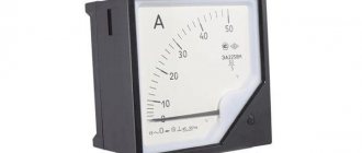
- An ammeter is a device for calculating current in a circuit.
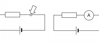
- The voltmeter is connected to the device in parallel, and the ammeter in series.
- Most analog meters are based on a galvanometer, which measures current by moving or deflecting a needle. Deflection is affected by the magnetic force acting on the conductive wire.
Operating principle
The measurement method is based on the operation of several elements:
- On the axis between the permanent magnets there is an armature with an arrow.
- Thanks to the influence of magnets, the steel anchor is located along the power lines, in the zero position.
- When current is applied, a magnetic flux appears with lines of force perpendicular to the magnets.
- As a result of this effect, the armature tends to turn at a right angle, which is prevented by the main magnetic field.
- The final deviation of the arrow is the result of the interaction of two flows.
Due to the simple principle of operation of the ammeter, mechanical devices for a long time differed only in the material used to make the elements.
Voltmeters
A voltmeter is a device for calculating the difference in electrical potential between two points in an electrical circuit. An analog voltmeter moves the pointer along the scale in proportion to the voltage in the circuit; a digital voltmeter has a digital display. Any voltmeter measurement that can be converted to voltage will appear on the meter. Pressure, temperature and flow will be recorded here.
Demonstration device used in physics lessons
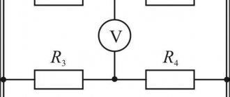
For a voltmeter to calculate voltage, it must be connected in parallel. This is important because parallel objects experience a single potential difference. Below is a diagram of the voltmeter and readings.
(a) - To calculate the potential difference in this current, a voltmeter (V) is placed in parallel with respect to the voltage source or any of the resistors. Note that the terminal voltage is calculated between points a and b. You cannot connect a voltmeter through the EMF without adding internal resistance. (b) – Application of a digital voltmeter
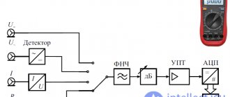
Video about the principles of operation of electrical measuring instruments
What does a voltmeter measure and how to use it
XXI CENTURY Candy Fudge Scented water
266 ₽ More details
Video baby monitor Motorola MBP36S (white)
12900 ₽ More details
Men's camouflage jackets
Ammeters
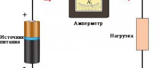
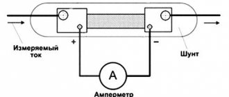
An ammeter measures electric current, and its name comes from the unit of measurement - Ampere. In order for the device to detect current, it must be connected in series. This is important because objects in a series circuit experience a single current. They do not have to be connected to a voltage source - ammeters operate at minimal load. You can look at the ammeter circuit.
An ammeter is installed in series connection to determine the current. All current in the circuit passes through the meter. If the ammeter is between points d and e or f and a, it will acquire the same value
Origin story
By the name of the device you can guess who had a hand in its creation. André-Marie Ampère was a brilliant scientist of his time who devoted many years to electrodynamics. He is responsible for many significant discoveries in this area:
- interaction of magnetic field and electric current;
- magnetic effect of a current-carrying coil;
- introduction to scientific terminology of the concepts of cybernetics and kinematics.
The scientist’s main merit is not the development of the device, but the preparation of a scientific springboard for the very possibility of creating an ammeter and voltmeter. Therefore, the first mentions of the measuring device date back to the 20s of the 19th century, when Ampere himself was already over 50.
Then we were talking about the simplest device - a galvanoscope, consisting of a twisted wire and a magnetic needle. It made it possible to capture relative indicators based on the degree of deviation of the needle.
Over the next decades the design was improved. In 1884, domestic scientists developed more advanced devices, but the patents were transferred to Germany due to the insufficient development of electrical production. Only by that time were the names of modern quantities approved. In 1881, in relation to current, a decision was made about how force was measured - in Amperes.
How do ammeters work today? The housing with the indication contains a measuring coil and permanent magnets that align it when an electric current is applied. The stronger the deviation, the higher the indicator of the device. There are several varieties, differing in design and scope.
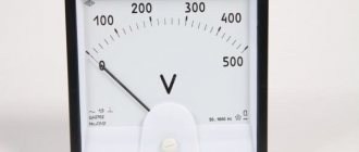
For your information. The classic type is a device with a scale, the divisions of which indicate the current strength in Amperes. Depending on the value, the moving element rotates the arrow at a certain angle.
Galvanometers (analog meters)
Analog meters have needles that rotate to mark numbers on a scale. This distinguishes them from digital devices that display digital symbols directly on the screen. At the center of most analog instruments is the galvanometer (G). Current passes through it and causes proportional movement (needle deflection).
A galvanometer is characterized by resistance and current sensitivity. The latter is the current that causes a significant deflection of the galvanometer needle (maximum current). For example, a galvanometer whose current sensitivity is 50 μA reaches a maximum deflection of 50 μA.
If such a device has a resistance of 20 ohms, then only the voltage V = IR = (50 µA) (25 ohms) = 1.25 mV creates a full-scale reading. By combining resistors with it, you can consider it as a voltmeter or ammeter.
Galvanometers as voltmeters
A galvanometer coil is capable of functioning as a voltmeter when placed in series connection with a significant resistance (R). This value is calculated by the maximum voltage. Let's say you want 10V to produce the full scale deflection of a voltmeter housing a 25 ohm galvanometer with a sensitivity of 50 µA. Impedance:
Rtotal = R + r = V/I = 10V/50μA = 200kOhm,
or
R = Rtotal - R = 200 kOhm - 25 Ohm ≈ 200 kOhm (R is so high that the resistance of the galvanometer is almost negligible).
Note that the applied 5V creates a half-scale deflection, sending only 25 µA of current through the meter, since the voltmeter reading is positioned proportionally. In the case of other ranges, the voltage is set in series with the galvanometer.
Built-in miniature digital voltmeters from China: review and application details
To monitor the operation of equipment, constantly operating instruments are useful - voltmeters, ammeters, etc. Constant monitoring of parameters will help the user understand whether everything is in order with the equipment, or “something went wrong.” This review will present two miniature digital voltmeters: 30 Volt and 100 Volt. They are similar, but not the same.
Voltmeters are designed to measure direct voltage of positive polarity.
Design of digital voltmeters
Both voltmeters are frameless; and due to the very small size of the board with electronics, at first it may seem that they consist only of indicators:
This photo immediately shows the difference between a 100 V voltmeter (left) and a 30 V voltmeter (right): a 100 V voltmeter has a 3-wire connection, and a 30 V voltmeter has a two-wire connection.
Why is this done?
Everything is very simple: voltmeters use a linear stabilizer with a maximum input voltage of 30 V. Therefore, the “junior” voltmeter can be powered directly from the measured voltage, and the “senior” voltmeter, when used to measure voltages above 30 V, requires a separate source for its power supply.
If a 100-volt voltmeter is used to measure voltages up to 30 V, then you can short the red and yellow wires together and also power them from the measured voltage.
But, as usual, there is a nuance. If you power the device from the measured voltage, then it should be no lower than what is needed to power the voltage stabilizer in the device, and this is 5 V (recommended by the seller). That is, in this case, the measured voltage must be at least 5 V (tests have shown operability at 4 V, but this is not guaranteed for the entire temperature range; and no one has canceled the spread of parameters of the elements on the voltmeter board).
The voltmeters were purchased on Aliexpress HERE, the price (at the date of review) was ridiculous: from $0.76 for a 30-volt device and up to $1.35 for a 100-volt device.
A few words about the dimensions of voltmeters.
If we talk about the dimensions briefly, the dimensions of the devices are 30.2 x 11 x 8.6 mm.
Broken down by detail, the dimensions will be as follows: board length - 30.2 mm, board width - 11 mm, display block length - 22.6 mm, display block width - 10.4 mm, display block height (from the board level) - 6.2 mm, height of the entire device ( from the bottom of the board to the top of the indicator) - 8.6 mm.
The height of the numbers on the indicator is 7.1 mm (0.28 inches).
Let's look at the reverse side of voltmeters, i.e. on boards with electronics:
The voltmeter boards are absolutely identical, and differ only in the location of two elements (these locations are indicated by arrows in the photo).
That is, if you wish and have “direct hands,” you can transform one of them into another and vice versa. But there is no economic sense in this; it is better to immediately buy whichever one you need (or, if in doubt, both at once).
The purpose of the wires is obvious: black is ground, red is power (it is also the measured voltage for a 30-volt device), yellow is the measured voltage.
There are very few parts on the voltmeter boards.
The basis of voltmeters is an analog-to-digital microcontroller, alas, without markings. However, there were no complaints about his work.
The microcontroller performs analog-to-digital signal conversion; then, probably, some simple computational processing (perhaps averaging several measurements); and then sends the result to the 3-digit LED indicator.
The microcontroller is powered by stabilizers marked “7533-1 E1125D” and “6513 TA502H”.
Both stabilizers produce an output voltage of 3.3 V, and are most likely clones of the popular AMS1117 stabilizers.
There is a trim resistor for calibrating voltmeters.
That's all, actually.
Testing digital voltmeters
I must immediately say the main thing: the tests tested the accuracy of the settings of the voltmeters in the form in which they came from China. There is no point in checking the accuracy simply “as such,” since the instruments have calibration adjustments that allow you to adjust the settings of the voltmeters if the reading error turns out to be high.
The test program is as follows: first we check the accuracy of a 100-volt voltmeter, and then the synchronism of the voltmeter readings when measuring the same voltage.
We will also check the current consumption of the devices and the input resistance for a 100-volt device.
So, let's go.
Checking the accuracy of the factory setting , voltage - 5 Volts:
Everything is fine, the error is less than 1%.
Voltage - 12 V:
Here, formally, there is no error at all, but this means, most likely, that both devices are mistaken. 
Please note: after 10 Volts on the tested voltmeter, the decimal point jumped by 1 digit, and now the device does not show hundredths of a Volt.
Let's move on.
Voltage - 30.1 V:
Likewise, there seems to be no error.
Next I would need to check at a voltage of 100 V, but I didn’t have such a power supply. The maximum that was found was voltage - 49.4 V:
A small error of 0.1 V was found here.
A 100 V voltmeter allows you to measure voltages lower than its supply voltage. But the accuracy will drop for a trivial reason: due to too much “weight” of the error per unit of the least significant digit.
You can measure, for example, the voltage on the battery:
Now let’s check the coincidence (or discrepancy) of the voltmeter readings with each other for two voltages (4 V and 30 V):
The agreement between the voltmeter readings turned out to be very good.
Now - an example of the practical application of one of these voltmeters.
I attached a low-grade voltmeter (30 V) to a QC trigger, designed to receive voltages of 9 and 12 Volts from power banks and QC chargers (review of a QC trigger with a power bank).
This trigger sends a command to the connected device to output 9 or 12 V, but does not check its execution.
Now there is a check:
In this photo, another feature of the wills on the indicator turned out to be clearly visible; it glows brighter than other numbers.
Probably, the voltmeter supplies each of the 3 digits of the indicator with the same current, and for illumination it bypasses them one by one; As a result, the smaller the number of active segments in a digital number, the brighter they glow.
This cannot be called a significant problem, but attention should be paid to it.
Now - about current consumption by voltmeters .
A 30 V voltmeter (with a red indicator) consumes 11 mA, a 100 V voltmeter (with a yellow indicator) consumes noticeably more, almost 16 mA.
When the voltmeter was powered at 100 V from a source with a voltage of 30 V, the heating of the stabilizer on the device board was very noticeable (the result was 0.4 W of power dissipation on the stabilizer).
Hence the recommendation: power a 100-volt device with a voltage of no more than 20 V. The best option is with a voltage of 5 V, which is available almost everywhere.
The reason for the higher consumption of this voltmeter may lie in the higher consumption of its indicator (everything else is the same).
The input impedance of a 100-volt device is 100 kOhm.
There is no point in talking about the input resistance of a 30-volt device, since the input there is combined with the power supply.
The range for adjusting the accuracy of voltmeters using a trimming resistor on the board is about 8%.
Results, conclusions, subtleties of application
First, about the subtleties of application when measuring negative voltages .
If the voltage does not exceed 30 V, then everything is done simply: the ground of the voltmeter is connected to the minus of the power supply, and the plus of the voltmeter to the ground of the power supply. And everything works right away!
If the measured voltage exceeds 30 V, then everything becomes much more complicated.
In this case, it is possible to use only a 100-volt device; Moreover, to power it you will need a separate isolated source (in bourgeois terminology - floating or even flying).
This is a serious complication of the circuit, which is why it makes sense to think about other devices for similar measurements.
Theoretically, instead of an isolated power source, it is possible to extinguish the excess voltage with a resistor or zener diode; but such a solution is not beautiful and limits the range of operating voltages.
Now - about the advantages of the tested voltmeters .
The advantages are:
- low price;
- good measurement accuracy;
- Possibility of power supply with measured voltage;
- small dimensions and weight.
The advantages are very significant, but disadvantages :
- lack of brightness adjustment (in the dark the indicator glow feels too bright, and in bright light it feels dull);
- the presence of a strobe effect (when moving the eyes or the voltmeters themselves);
- do not measure alternating voltage;
- difficulties with measuring negative voltages above 30 V.
You can check the current price or buy tested voltmeters here, and there is a wide selection of indicator colors (in addition to those tested with yellow and red).
Thank you all for your attention!