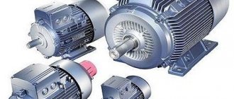
A power transformer is a non-standard product, which is often used by radio amateurs, industry and in the design of many household appliances. This concept means a winding device made on a metal core made of electrical steel plates. Few such products are standard, so most often radio amateurs make them themselves. Therefore, the question is very relevant: how to calculate a transformer based on the cross-section of the core using a calculator for this?
Required information
To manufacture a winding product, it is necessary to be guided by a lot of information. The quality and service life of the finished power supply will directly depend on this. You should approach the calculation process competently, taking into account indicators such as magnetic inductance, efficiency and current density. Otherwise, the product will turn out to be unreliable and will soon fail. The main characteristics include:
- Mains input voltage. It depends on the source to which the transformer will be connected. The standard ones are: 110 V, 220 V, 380 V, 660 V. In practice, it can be anything, depending on the characteristics of the intermediate circuits.
- The output voltage of the transformer is the value required to ensure stable operation of the consumer. It is often necessary to manufacture a product with multiple ratings or with adjustable voltage. Then it is necessary to take into account its maximum value.
- Load current. With a fixed value, the rigid characteristics of the device are calculated, but often it is necessary to provide an adjustable value, then it will be necessary to take into account its maximum value.
- Network frequency. We use the European standard, that is, 50 Hz.
- Load power. This is not the main parameter, because it can be determined by voltage and current.
- Number of output windings. Some electronic devices use power supplies with multiple output voltages. For the manufacture of power electronics, mainly one rating is used, for example, for welding transformers.
You will also need to take into account the type of core , because the principle of calculating product performance directly depends on its design. There are many varieties of both designs and materials. If taking the latter into account makes no sense due to minor errors, then shape and size are of great importance. Therefore, different calculation algorithms are needed, depending on this criterion. Let's start with the simplest and most common.
It is not always necessary to carry out calculations using the required data. Often there is some kind of iron available, then you will need to determine the power of the transformer based on the cross-section of the magnetic circuit. Online programs available on the Internet allow you to determine parameters in any order.
How the device works
A transformer is an electrical device designed to transmit energy without changing its shape and frequency. Using the phenomenon of electromagnetic induction in its work, the device is used to convert an alternating signal or create galvanic isolation. Each transformer is assembled from the following structural elements :
- core;
- windings;
- frame for winding arrangement;
- insulator;
- additional elements ensuring the rigidity of the device.
The principle of operation of any transformer device is based on the effect of the appearance of a magnetic field around a conductor with an electric current flowing through it. This field also occurs around magnets. Current is the directional flow of electrons or ions (charges). By taking a wire conductor and winding it around a coil and connecting a potential measuring device to its ends, you can observe a surge in the voltage amplitude when the coil is placed in a magnetic field. This suggests that when a magnetic field is applied to a coil with a wound conductor, an energy source or energy converter is obtained.
In a transformer design, such a coil is called primary or mains . It is designed to create a magnetic field. It is worth noting that such a field must necessarily change in direction and magnitude all the time, that is, be variable.
A classic transformer consists of two coils and a magnetic circuit connecting them. When an alternating signal is applied to the contacts of the primary coil, the resulting magnetic flux is transmitted through the magnetic circuit (core) to the second coil. Thus, the coils are connected by magnetic power lines. According to the rule of electromagnetic induction, when the magnetic field changes, an alternating electromotive force (EMF) is induced in the coil. Therefore, a self-induction emf occurs in the primary coil, and a mutual induction emf occurs in the secondary coil.
The number of turns on the windings determines the amplitude of the signal, and the diameter of the wire determines the greatest current strength. If the turns on the coils are equal, the input signal level will be equal to the output. In the case where the secondary coil has three times as many turns, the amplitude of the output signal will be three times greater than the input - and vice versa.
The heating of the entire device depends on the cross-section of the wire used in the transformer. It is possible to select the correct cross-section using special tables from reference books, but it is easier to use an online transformer calculator.
The ratio of the total magnetic flux to the flux of a single coil sets the strength of the magnetic coupling. To increase it, the windings of the coils are placed on a closed magnetic circuit. It is made from materials with good electromagnetic conductivity, for example, ferrite, alsifer, carbonyl iron. Thus, three circuits arise in the transformer: an electrical circuit - formed by the flow of current in the primary coil, an electromagnetic circuit - forming a magnetic flux, and a second electrical circuit - associated with the appearance of current in the secondary coil when a load is connected to it.
The correct operation of the transformer also depends on the frequency of the signal . The larger it is, the less losses occur during energy transfer. This means that the dimensions of the magnetic circuit depend on its value: the higher the frequency, the smaller the dimensions of the device. Pulse converters are built on this principle, the manufacture of which is associated with development difficulties, so a calculator is often used to calculate a transformer according to the core cross-section, which helps to get rid of manual calculation errors.
Calculation of armor transformer
A common type of transformer is used in almost all devices, from chargers for screwdrivers to power supplies for tape recorders. During the operation of all these devices, breakdowns often occur in the feeder associated with a burnt winding product. Then to restore it you will need to rewind, but this does not solve the problem.
It is often necessary to increase the power of the source, then how to calculate the transformer so that its iron does not overheat? You will need to choose larger iron and use thicker wire. This move will help maintain the functionality of the device and even improve its performance, making it more stable and resistant to power surges in the network.
Unfortunately, not all manufacturers take this factor into account, but our network is unstable and regularly experiences interference in the form of high-voltage needle pulses. Situations also arise when there is a drop in the network to 170 V, which is typical in winter. Then it is necessary to provide a voltage reserve of at least 40-45%, increasing the power of the compensation stabilizer. Such situations are often observed in the private sector.
Let's return to the calculation of the W-shaped transformer on the ShP core . The principle will be the same with a PL-type core, provided the winding is placed on the middle part. To do this you will need to complete the following steps:
- Determine the cross-sectional area of the middle part of the core. It is expressed by the letter S sec. and is found from the product of its sides. Taking a ruler, we measure the parameters of the section, multiply and get the value in square centimeters.
- At the next stage, the question of how to calculate the power of the transformer is resolved. This is a calculated value that can be determined by constructing S section. into a square. The value will be measured in W and denoted by the letter “P”.
- When calculating the power of the core, it is necessary to take into account the type of plates used. For example, if Sh-20 were used for the set, then the total thickness of the core should be 30 mm with a power of 36 W. If Sh-30 plates were used for the transformer, then the thickness of the set will be 20 mm, and when using Sh-24 - 25 mm. There are reference tables in which you can find the power of the transformer according to the cross-section of the magnetic circuit for a specific situation. To ensure the best stability of power supplies, you should use iron with at least 25% excess power. That is, if the previously calculated power was 6 W, then for reliable operation and to avoid core saturation, at least 8 W should be taken into account. This is a must. If you use a magnetic core with a smaller core cross-sectional area, the transformer will quickly fail because the iron will be saturated, which will lead to an increase in currents in the windings.
- At the next stage, you need to decide on the number of windings. For modern transistor devices, just one or double with a midpoint will be enough. Therefore, let’s consider an example of calculating just such a transformer. To do this, you will need to use the concept of “volts per turn.” The value is determined as follows: W /B=(50÷70) / S section. The formula is valid only for cores of the ShP and PL types. When calculating the primary and secondary windings, you will need to take the product of the resulting ratio and the input voltage: W1 = W / B∙U1, W2 = 1.2 ∙ W / B∙U2.
- The wire diameter is calculated and selected. It is selected based on good heat dissipation and insulation, for which it is recommended to use PEL or PEV coated with varnish. Its size can be determined by the formula: d =0.7∙√ I. The value is expressed in mm. The wire is selected with a small margin of up to 4-6%.
All transformer calculation programs allow you to find product parameters in any order. They use standard algorithms by which values are derived. If necessary, you can create your own calculator using Excel spreadsheets. The calculator for calculating a transformer on a rod core works in a similar way.
How to choose a transformer
When choosing a transformer, it is necessary to take into account the requirements for the device, first of all, power and design. In addition, you should decide on the number of transformers. If you need two pieces, you should ensure that they have the same power.
When choosing a transformer, you should take into account external technical characteristics, as well as other nuances and features:
- Voltage level – indicators of input and output voltage;
- Design;
- Rated voltage;
The correct choice of transformer device can only be made by a specialist.
Calculation programs
There are many programs that offer online calculation of the parameters of any transformer with an armored or rod core. One of these could be the service on the “skrutka” website. To determine the characteristics, you will need to indicate a number of the following data:
- input voltage - U1;
- output voltage - U2;
- plate width - a;
- stack thickness - b;
- network frequency - Hz;
- overall power - V*A;
- efficiency;
- magnetic inductance of the magnetic circuit - T;
- current density in the windings - A/mm sq.
The last 4 values are tabular, so you will need to use a reference book.
It is necessary to competently and responsibly calculate the parameters of the transformer , because the quality of the functioning of your power supply will depend on the quality of the work performed. You shouldn't always rely on programs; they may contain errors. Select one or more parameters and recalculate them manually using the previously given formulas. If you get approximately the same value, then the result can be considered correct.
Recommendations for assembly and winding
When assembling a transformer with your own hands, the core plates are assembled “over the roof”. The magnetic core is tightened with a clip or hairpin nuts. In order not to damage the insulation, the studs are covered with a dielectric. You need to tighten the hardware with force: if it is not enough, a hum will occur during operation of the device.
The conductors are wound onto the coil tightly and evenly, each subsequent row is insulated from the previous one with thin paper or Mylar film. The last row is wrapped with keeper tape or varnished cloth. If a tap is made during the winding process, the wire breaks, and a tap is soldered in place of the break. This place is carefully isolated. The ends of the windings are secured with threads that tie the wires to the surface of the core.
There is a trick: after the primary winding, you should not wind the entire secondary winding at once. Having wound 10-20 turns, you need to measure the voltage at its ends.
Based on the obtained value, you can imagine how many turns will be required to obtain the required amplitude of the output voltage, thereby controlling the resulting calculation when assembling the transformer.
Selection of a step-down transformer based on power characteristics
If there is only one secondary winding, then it is easy to calculate the required output power of the transformer Pout using the following formula:
Pout=Uload• Iheat,
where Unload is the voltage drop across the load, and Iload is the load current.
Next, we select a transformer whose calculated value of Pout is less than the overall power. The overall power of a transformer refers to the maximum output power that can be obtained from a transformer with certain dimensions: an infinite number of wires cannot be placed in a finite physical volume. For example, a transformer with dimensions 10x10x10 mm cannot have a power of 10 kW.
If there are several secondary windings in a step-down transformer, then it becomes necessary to distribute the overall power between the windings; for this you need to clearly understand whether the secondary windings will be loaded simultaneously or not. In the case when the secondary windings are loaded simultaneously, it is necessary to select a step-down transformer based on the condition that its overall power must exceed the total power of all loads, otherwise the transformer will operate with overload.
It often happens that you already have similar step-down transformers in stock. How to use them so as not to buy new ones?
The secondary windings can be connected in parallel. What does this give? The ability to pass more current at the same voltage. But be careful: the parameters of the secondary windings must match, otherwise one of them (the one designed for higher voltage) will become heavily overloaded, and the secondary windings with lower voltage will be underloaded or will not work at all.
The output power in this case is calculated as follows:
Рout=Uout•(Iheat1+ Iheat2+…+ IloadN),
where Iload1, Iload2, etc. is the load current of each of the secondary windings. If you do everything right, they will be the same.
The secondary windings can be connected in series. Why might this be needed? Let's consider an example: you have a step-down transformer with two secondary windings of 12 V, and you need a transformer with one secondary winding with a voltage of 24 V. In this case, if you connect two secondary windings of 12 V in series, you will get one secondary winding with voltage 24 V. The power when connecting the secondary windings in series can be calculated as:
Рout=(Uout1+Uout2+…+UoutN)•Iload,
where Uout1, Uout2, etc. – these are the voltages of each of the secondary windings.
The output power of the transformer must be taken with a reserve if there are additional requirements for limiting the no-load current, open-circuit voltage and overheating.
After this, we select the size of the step-down transformer within the limits of overall power. It is also necessary to take into account that the actual overall power of the transformer will be lower than that declared by the manufacturer if there are several secondary windings.
Types of current transformers
It is necessary to select a device suitable for the mains voltage or specific work based on classification according to various criteria.
Purpose
There are such transformers:
- measuring - measure the parameters of the circuit;
- protective – prevent overloads and equipment failure;
- intermediate – connected to a circuit with relay protection, equalizing currents in differential protection circuits;
- laboratory ones are highly accurate.
Laboratory models have higher conversion factors.
Installation type
For a private house or apartment, you can choose a device that can be installed indoors or outdoors. Some modifications are built into the equipment and are also placed on the bushing. Portable models are used for measurements and laboratory tests.
Primary winding design
There are bus, single-turn (with a rod) and multi-turn (with a coil, loop-type winding and figure-of-eight) devices.
Insulation type
The following converters are available:
- dry insulation - based on cast epoxy, porcelain or bakelite;
- paper-oil – standard or condenser;
- gas-filled - inside there is inorganic SF6 gas with a high breakdown voltage;
- compound - inside there is a filling of thermoactive and thermoplastic resin.
The compound has the highest moisture resistance.
Depending on the number of transformation stages, you can select single-stage and cascade models. The entire line has an operating voltage of more than 1000 V.
Step-down transformer - what do we mean?
This article will focus on transformers used in power circuits of electronic equipment. Such transformers are called power transformers and are used in transformer power supplies for radio-electronic equipment to obtain the supply voltage of the required values.
Power transformers convert alternating current of one voltage into alternating current of another voltage. The primary winding of these transformers is usually designed for mains voltage of ~220 or ~380 V, 50 Hz. As a rule, power transformers are step-down with the voltage on the secondary winding 3; 6; 9; 12; 15; 18 V, etc.
Step-down transformers used in electronic equipment are usually produced in a dry design, and can, if necessary, be cooled by a fan while operating as part of a power supply.
Accuracy class
The accuracy class of a current transformer is specified in GOST 7746-2001 and depends on its purpose, as well as the parameters of the primary current and secondary load:
- Under conditions of low resistance, almost complete shunting of the magnetized branch occurs. The device operates with a large error.
- As the resistance increases, the error also increases. The reason is the operation of the device in the saturation region.
- At the minimum primary current rating, the transformer operates in the lower part of the magnetized curve, at the maximum, at the saturation section.
The exact selection of a transformer by accuracy class can be made based on the table.
| Accuracy class | Primary current rating in % | Secondary load limit in % |
| 0,1 | 5, 20, 100-200 | 25-100 |
| 0,2 | ||
| 0.2S | 1,5, 20, 100, 120 | |
| 0,5 | 5, 20, 100, 120 | |
| 0.5S | 1, 5, 20, 100, 120 | |
| 1 | 5, 20, 100-120 | |
| 3 | 50-120 | 50-100 |
| 5 | ||
| 10 |
For protection devices, the accuracy class is also determined from the table.
| Accuracy class | Maximum error | Percentage of maximum secondary load | ||
| thermal | corner | |||
| min | Wed | |||
| 5P | ±1 | ±60 | ±1,8 | 5 |
| 10R | ±3 | There is no norm | 10 | |
For energy metering, models with an accuracy class of 0.2S - 0.5 are used, for ammeters with minimal sensitivity - with 1st or 3rd, for relay protection - 5P and 10P.
Reliability of voltage instrument transformers in a network with an isolated neutral
A simple measuring device is designed to derate the voltage that is supplied to meters and protective relays connected to a 6-10 kV network. The transformer operates properly only when the neutral is grounded.
In case of ferroresonance reactions (power line phase failure, contact with branches, dew drops running down wires, incorrect switching), there are risks of voltage transformer breakdowns. The failure rates are 17 and 25 Hz. Under these conditions, an overcurrent flows through the primary winding and it burns out.
If the "Star-Star" circuit is used, under conditions of increasing voltage the induction of the magnetic circuit increases. The device burns out. You can prevent this process by:
- reduction of working induction rates;
- connecting resistance-damping devices to the network;
- creating a three-phase device with a common five-rod magnetic system;
- operation of devices connected to the network when the delta is opened;
- grounding of the neutral through a current-limiting reactor.
The simplest option is to use special windings or relay circuits.
Selection of design
According to their design, transformers are divided into:
- oil The advantages include good insulating properties and parameters of transformer oil, low cost. Disadvantages include a high probability of fire in the event of internal damage to the insulation or improper operation of the protection system. Oil-based types of devices are installed as outdoor installations or in special locations in substations located outside buildings.
- Dry - oil-free, using various insulating materials - synthetic resin, quartz powder filler and others. They are located inside the building, closer to the center of electrical loads.
Possible errors when choosing
Many transformer devices are simple in design, reliable and easy to use. However, such a device does not allow full operation and operation in case of deviations in parameters such as voltage, current, power. If there is a deviation of the parameters beyond the permissible values, the unit must be taken out of operation.
The following factors influence damage to transformer devices:
- non-compliance with operating rules;
- uncontrolled operating mode, which can cause overheating or overload of the transformer;
- aging of winding insulation;
- poor quality assembly during installation or repair;
- factory defect.
Even an expensive transformer will not last forever. However, regularly performed diagnostics and timely repairs will help increase the life of the device.